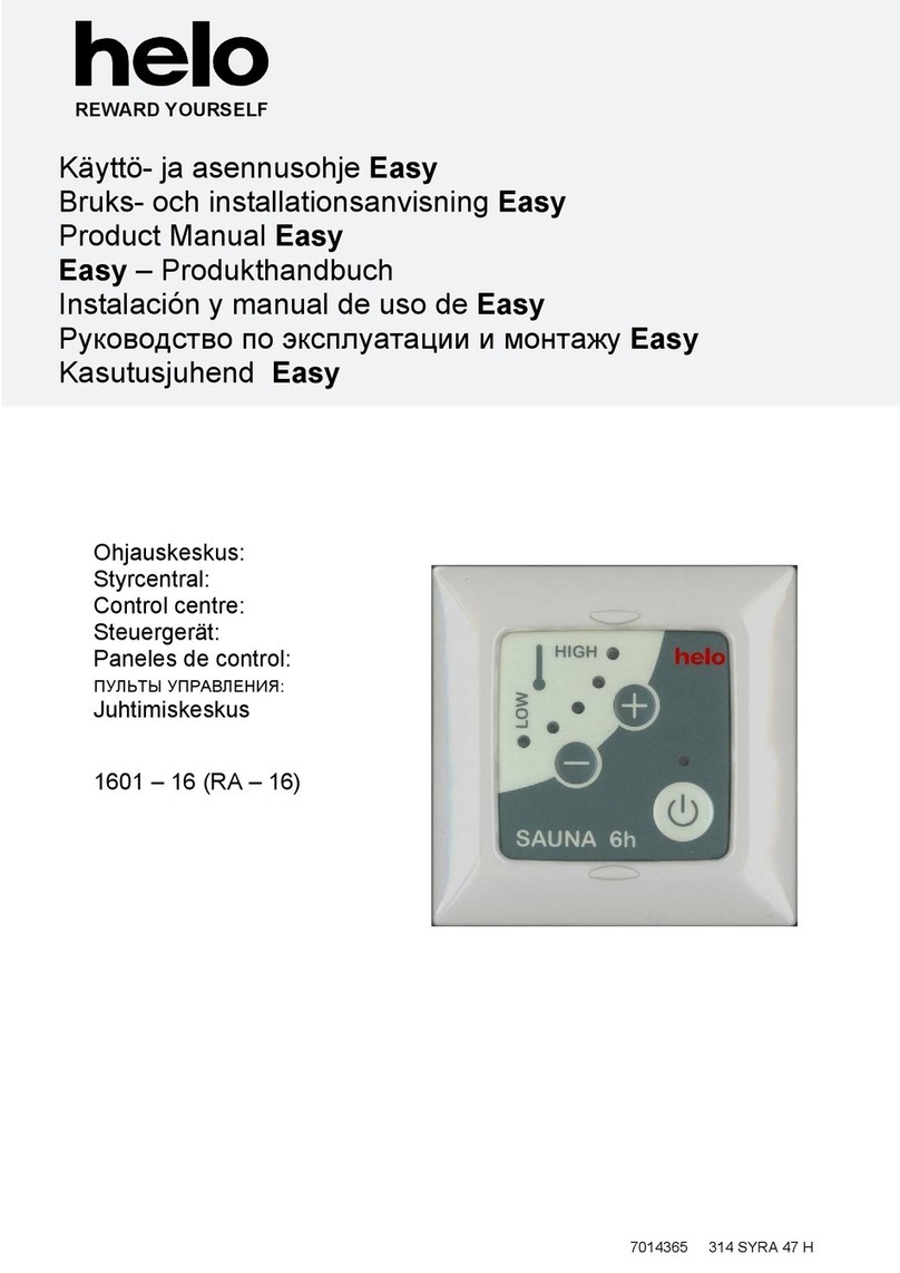
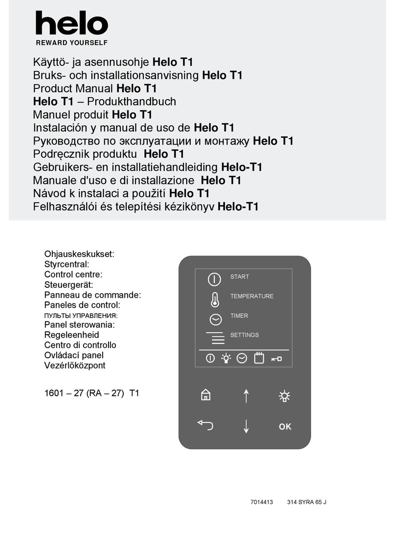
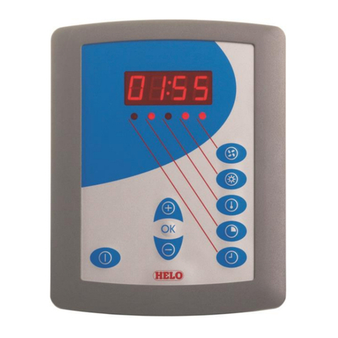
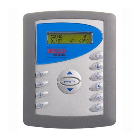
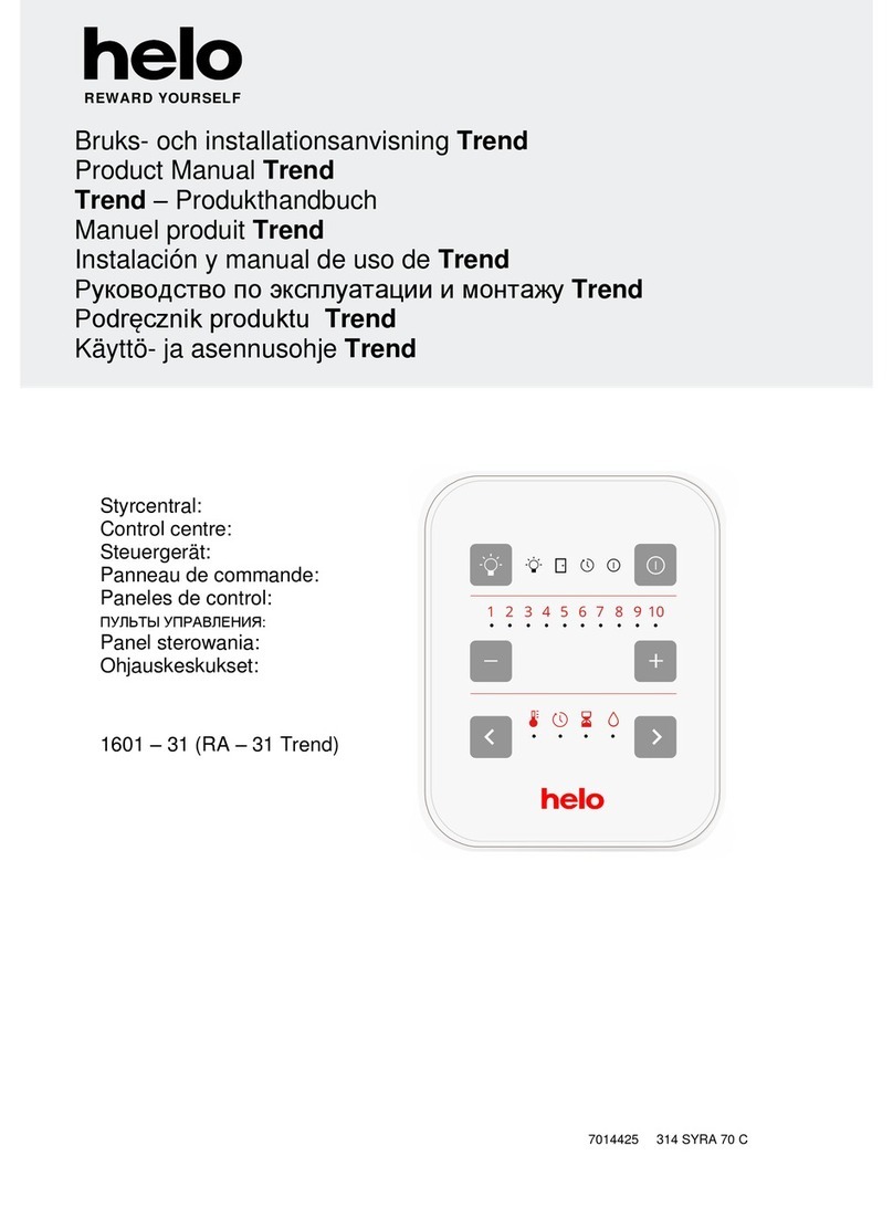
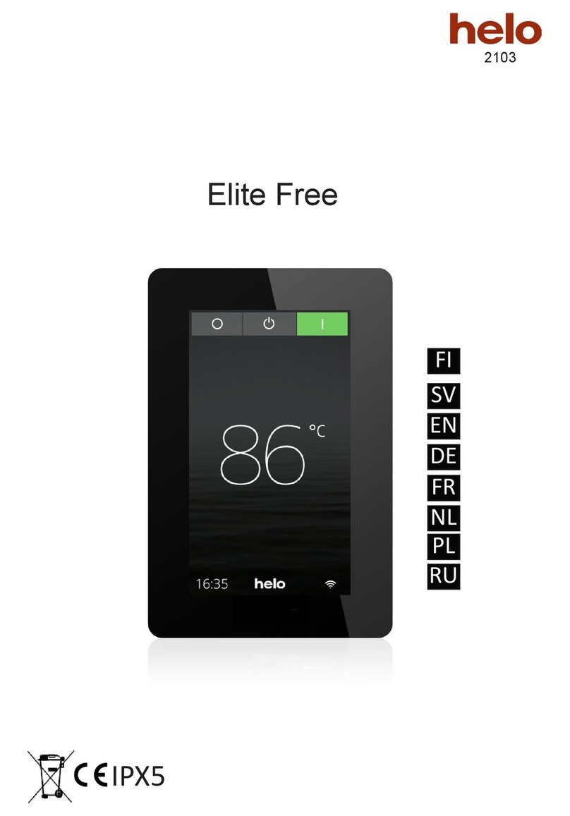
Helo WE-50 Operating manual

Contactor box WE - 50 (2005 –50) 400-415V 3N~
WE - 51 (2005 –51) 400-415V 3N~
WE - 52 (2005 –52) 230-240V 3~
Control panels
- Premium Wifi (1601 –33)
- Trend (1601 –31)
Premium Wifi Trend
Contactor box WE - 50
314 SYWE 31-3 A
User and installation manual
REWARD YOURSELF

Contents Page
1.1. Check before taking a sauna bath 3
1.2. Sauna room 3
1.3. Operation of the sauna heater controls 3
1.4. Operation of the sauna heater controls 3
1. Preparing for sauna heater installation 4
2. Installation 4
3. Safety clearances for sauna heaters 1101 and 1105 –XX …….. 5
4. Safety clearances for sauna heaters 1106 –XX (SKLF / Octa) 6
5. Cables and fuses for heaters 1105 –XX (SKLE / Laava) 7
6. Cables and fuses for heaters 1101 –XX (SKLA / Magma) 7
7. Cables and fuses for heaters 1106 –XX (SKLF / Octa) 7
8. Using the contactor cases 8
9. Locating the connecting box for the connection cable in the sauna room 8
10.Door switch 9
11.Remote controlling 9
12.Wiring diagram WE - 50 and 52 10
13.Wiring diagram WE - 51 11
14.Principle diagram 12
15.Connection principle 13
16. Internal connection for sauna heaters SKLE / LAAVA 14
17.Circuit board RJ connectors 15
18.Installation of two SKLA/Magma heaters in a sauna room. 16
19.ROHS 17
Figure and Tables
Figure 1. Installation location of the OLET 31 ……… 5
Figure 2. Alternative installation location of the OLET 31 sensor…… 5
Figure 3. Safety clearances to heater SKLF / Octa 6
Figure 4. Location for the connection box 8
Figure 5. Pin layout of a RJ10 circuit 9
Figure 6. Installing the door switch 9
Figure 7. Wiring diagram for contactor box WE - 50 and 52 10
Figure 8. Wiring diagram for contactor box WE - 51 11
Figure 9. Principle diagram of connection 12
Figure 10. Principle diagram of connections 13
Figure 11. Internal connection for sauna heaters SKLE / Laava 14
Figure 12. Internal connection for sauna heaters SKLF / Octa 14
Figure 13. Internal connection for sauna heaters SKLA / Magma 15
Figure 14. Installation of two heaters in a sauna room. 16
Figure 15. Installation of the sensors of two sauna heaters……… 16
Table 1. Safety clearancest to heater 1105 –xx (SKLE / Laava) 5
Table 2. Safety clearances 1101 –xx (SKLA / Magma) 6
Table 3. Safety clearances to heater 1106 –xx (SKLF / Octa) 7
Table 4. Kables and fuses for heater 1105 –XX (SKLE / Laava) 7
Table 5. Kables and fuses for heater 1101 –XX (SKLA / Magma) 7
Table 6. Kables and fuses for heater 1106 –XX (SKLF / Octa) 7
Table 7. Connecting the door switch to an RJ10 connector. 9
Table 8. Instructions for connecting OLEA 103 RJ 10 circuit board for remote control 9
Table 9. Circuit board RJ connectors 15
Table 10. Safety distances in a two-heater installation. 17
User and installation manual
2

WARNINGS
1.1. Check before taking a sauna bath
1. The sauna room is suitable for taking a sauna bath.
2. The door and the window are closed.
3. The sauna heater is topped with stones that comply with the manufacturer's
recommendations, the heating elements are covered with stones, and the stones
are piled sparsely.
NOTE! Ceramic rocks are not allowed.
The heater's main switch is located at the bottom of the heater, on the right side as
seen from the front.
The main switch is marked with a 0 –1 sticker.
1.2. Sauna room
The walls and ceiling of a sauna room should be thermally well insulated. All
surfaces that store heat, such as tiled and plastered surfaces must be insulated. It is
recommended to use wooden panel cladding inside the sauna room. If there are
heat storage elements in the sauna room, such as decorative stone, glass etc., note
that these elements may extend the pre-heating period even though the sauna room
is otherwise well insulated (see page 4, section 1. Preparing for sauna heater
installation).
1.3. Operation of the sauna heater controls
This appliance may not be used by children aged less than eight years, by persons
with reduced physical, sensory or mental capabilities, or by persons lacking
experience and knowledge regarding its operation only if such have been given
instructions on the safe use of the device and the risks involved. Children must not
be allowed to play with the appliance or to clean and service it without supervision.
(7.12 EN 60335-1:2012)
1.4. Operation of the sauna heater controls
Refer to the specific control panel operating instructions.
Rearrange the sauna stones at least once a year and replace any weathered
stones. This enhances air circulation between the stones, which extends the useful
life of the thermal resistors.
If you encounter any problems, please contact the manufacturer's warranty service
shop.
For additional information about enjoying a sauna bath, please visit our website at :
www.tylohelo.com
User and installation manual
3

1. Preparing for sauna heater installation
Check the following before installing the sauna heater.
-The ratio of the heater's input (kW) and the sauna room's volume (m3). Volume recommendations are presented
in Tables 1, 2 and 3 on page 5, 6 and 7. The minimum and maximum volumes must not be exceeded.
-The height of the sauna room must be at least 1900 mm or 2200 mm depending on the heater power.
-Uninsulated and masonry stone walls extend the preheating time. Each square metre of plastered ceiling or wall
surface adds 1.2 m3to the sauna room's volume.
-Check page 7 Table 4, 5 and 6 for a suitable fuse size (A) and the correct diameter of the power supply cable
(mm²) for the sauna heater in question.
-Conform to the specified safe clearance around the sauna heater.
-There should be enough room around the control panel for maintenance purposes. Also a doorway can be
considered as a maintenance area.
2. Installation
Follow the safety clearance specifications on pages 5, 6 and 7 on tables 1, 2 and 3 when installing the sauna
heater.
The sauna heater is a floor-standing model. The base must be solid, because the sauna heater weighs
about 80-130 kg.
The sauna heater is levelled by the adjustable legs.
The sauna heater is fixed on the floor from its legs by the provided metal fasteners (2 pcs). This will keep the safety
clearances intact during use.
Walls or ceilings must not be clad with fibre-reinforced plaster board or other light-weight cladding, because they
may cause a fire hazard.
Installing the sensor near a supply air vent
The sauna room air should be exchanged six times in an
hour. The diameter of the supply air pipe should be
between 50 and 100 mm.
A circular air supply vent (360°) must be
installed at least 1000 mm away from the sensor.
An air supply vent with a flow-directing panel
(180°) must be installed at least 500 mm away from
the sensor. Air flow must be directed away from the
sensor.
Ceiling installation of the sensor
In ceiling installation, a 5-mm hole must be drilled to the
sensor case to allow any condensed water to drain.
Do not spray water directly towards the sensor or splash
water at it with a sauna scoop.
Installing the Extra NTC sensor
The additional OLET 31 sensor is connected to the Ext NTC connector on the RJ10 circuit board. For more details,
refer to the switch diagram. The additional sensor is installed on the sauna room wall no more than 500 mm from
the ceiling. Once the additional sensor has been connected to the circuit board, it is automatically activated. This
means that the temperature shown on the control panel is measured by the additional sensor.
The primary sensor installed above the sauna heater only has the limiter circuit that limits the maximum tempera-
ture to 110 °C. Even if the temperature is set to 110 °C on the control panel, the maximum temperature that can be
shown on the panel is approximately 90 °C, as the primary sensor above the heater limits the maximum tempera-
ture to 110 °C. Depending on individual preferences, the temperature of a sauna room is typically set between 70
and 80 °C.
Ø 5mm
User and installation manual
4
360° 1000 mm
180° 500 mm
Sensor
Sensor

3. Safety clearances for sauna heaters 1101 and 1105 –XX (SKLE / Laava and
SKLA / Magma)
Power
kW
Sauna volum
Minimum distances
Adequate amount
of stones
Approx. kg
Min.
Max.
Minimi-
height
To the side
wall
To the
front
To the cei-
ling
To the
back
m3
m3
H
A
mm
D
mm
F
mm
C
mm
mm
9,0
8
13
1900
80
80
1200
110
60
10,5
9
15
1900
80
80
1200
110
60
12,0
10
18
2100
120
120
1400
120
60
15,0
14
24
2100
120
120
1400
120
60
Table 1 Safety clearancest to heater 1105 –xx (SKLE / Laava)
1
3
4
9
H
A
D
Max
500 mm
Min
100mm
40 mm
2
F
Figure 1. Installation location of the OLET 31 sensor
40 mm from the ceiling in the centre of the heater.
The safety distance between the heater and the wall
behind the heater must be at least the minimum dis-
tance listed in tables 1 SKLE / Laava and tables 2 for
the SKLA and Magma heaters.
Figure 2. Alternative installation location of
the OLET 31 sensor on a ceiling in the
centre above the heater.
1105-… SKLE / Laava
1. Contactor box WE - 50
2. Sensor OLET 31
3. Temperature resistant cable for sensor
4. Feed cable to the sauna heater
5. Connection box
6. Connection cable to the sauna heater
7. Lower bench or railing
8. Upper bench or railing
9. Control centre Trend or Premium wifi
Note! Alternative installation location of
the OLET 31 sensor on a ceiling in the
centre above the heater.
User and installation manual
5
6
D
H
5
7
8
2
F
C> min

Power
kW
Sauna volum
Minimum distances
Adequate amount
of stones
Approx. kg
Min.
Max.
Minimi-
height
To the side
wall
To the
front
To the cei-
ling
To the
back
m3
m3
H
A
mm
D
mm
F
mm
C
mm
mm
18
18
30
2100
140
160
1400
160
100
21
24
36
2100
140
160
1400
160
100
26
30
46
2200
140
160
1500
160
100
Table 2 Safety clearances 1101 –xx (SKLA / Magma)
4. Safety clearances for sauna heaters 1106 –XX (SKLF / Octa)
Figure 3. Safety clearances to heater SKLF / Octa
User and installation manual
6
1. Contactor box WE - 50
2. Sensor OLET 31
3. Temperature resistant cable for sensor
4. Feed cable to the sauna heater
5. Connection box
6. Connection cable to the sauna heater
7. Lower bench or railing
8. Upper bench or railing
9. Control centre Trend or Premium wifi
A min 560 D min
10 10
max
500 max
500
min
H
min
F
760
OLET 31
1
2
3
4
7
8
9
5
6
1106-… Octa
NOTE: The OLET 31
sensor is installed
directly on the ceiling,
in line with the side of
the heater.
Sensor installation area
Heater
1101-… SKLA / Magma
Note! Alternative installation location of
the OLET 31 sensor on a ceiling in the
centre above the heater.

Table 3 Safety clearances to heater 1106 –xx (SKLF / Octa)
5. Cables and fuses for heaters 1105 –XX (SKLE / Laava)
Model
Power
kW
Sauna heaters con-
nection cable
H07RN-F /
60245 IEC 66
mm2
400 –415V 3N~
1 –Power Group
Fuse
A
Sauna heaters
connection cable
H07RN-F /
60245 IEC 66
mm2
230V 3~
2 –Power Group
Fuse
A
1105 - 901
1105 -1051
1105 -1201
1105 -1501
9,0
10,5
12,0
15,0
5 x 2,5
5 x 2,5
5 x 6
5 x 6
3 x 16
3 x 16
3 x 25
3 x 25
2 x (4 x 2,5)
2 x (4 x 2,5)
2 x (4 x 2,5)
2 x (4 x 6)
2 x (3 x 16)
2 x (3 x 16)
2 x (3 x 16)
2 x (3 x 25)
Table 4 Kables and fuses for heater 1105 –XX (SKLE / Laava)
6. Cables and fuses for heaters 1101 –XX (SKLA / Magma)
Model
Power
kW
Sauna heaters con-
nection cable
H07RN-F /
60245 IEC 66
mm2
400 –415V 3N~
2 –Power Group
Fuse
A
Sauna heaters
connection cable
H07RN-F /
60245 IEC 66
mm2
230V 3~
2 –Power Group
Fuse
A
1101 -181
18 (9 + 9)
2 x (5 x 2,5)
2 x (3 x 16)
2 x (4 x 6)
2 x (3 x 25)
1101 -210
21
(9 + 12)
5 x 2,5
5 x 6
3 x 16
3 x 25
4 x 6
4 x 10
WE - 52
3 x 25
3 x 35
WE - 52
1101 -260
26 (13+13)
2 x (5 x 6)
2 x (3 x 25)
2 x (4 x 10)
WE - 52
2 x (3 x 35)
WE - 52
Table 5. Kables and fuses for heater1101 –XX (SKLA / Magma)
7. Cables and fuses for heaters 1106 –XX (SKLF / Octa)
Model
power
kW
Sauna heaters connection cable
H07RN-F/60245 IEC 66
mm²
400V –415V 3N~
1 –Power Group
Fuce
A
1106 –901
9,0
5 x 2,5
3 x 16
1106 –1050
10,5
5 x 2,5
3 x 16
1106 –1201
12,0
5 x 6
3 x 25
1106 –1501
15,0
5 x 6
3 x 25
Table 6. Kables and fuses for heater 1106 –XX (SKLF / Octa)
Power
Sauna room
Safety clearances min
Adequate amount
of stones
kW
Volum
m3
Min height
H
mm
On the sides
A
mm
In front
D
mm
To the ceiling
F
mm
Approx. kg
9,0
10,5
12,0
15,0
8-13
9-15
10-18
14-24
1900
1900
2100
2100
25
25
65
65
25
25
65
65
1150
1150
1350
1350
60
60
60
60
User and installation manual
7

8. Using the contactor cases
The contactor case 2005 –50 (WE –50), 2005 –52 (WE - 52) as well as an additional contactor case 2005 –51
(WE –51) supplied with the second heater can be used with the following sauna heaters:
- SKLE, LAAVA.…1105 - …. WE - 50 Power group 1 or 2 9 –15 KW 230V 3~ / 400V –415V 3N~
- SKLA, MAGMA...1101 - …. WE - 50 Power group 2 18 –26 kW 400V –415V 3N~
- SKLA, MAGMA…1101 - …. WE - 52 Power group 2 18 –26 kW 230V 3~
- SKLF, OCTA…. 1106 - …. WE - 50 Power group 1 9 –15 kW 400V –415V 3N~
The models of the control panels that can be used to control contactor cases WE - 50 and WE - 52 are 1601 –31
(Trend) and 33 (Premium Wifi).
Refer to the control panel operating manual for more specific instructions.
The contactor box is intended to be installed outside the sauna room. The cables must be installed using a fixed
installation. A connection box must be installed in the sauna room with a semi-fixed installation on the sauna
heater.
Failure to follow the minimum clearances in the installation instructions may cause a fire hazard.
Always check the sauna room before switching the sauna heater on.
9. Locating the connecting box for the connection cable in the sauna room
200 mm
A A
3.
2.
1.
500 mm
500 mm
Figure 4. Location for the connection box
A = Specified minimum safety clearance, see table 1, 2 or 3
1. Recommended location for the connecting box
2. Silumin box recommended in this area.
3. This area should be avoided. Always use a silumin box.
In other areas, use a heat-resisting box (T 125 °C) and heat-resisting cables (T 170 °C). The
connection box must be clear of obstacles. When installing the connection box to zones 2 or 3,
refer to the instructions and regulations of the local energy supplier.
User and installation manual
8

10. Door switch
The door switch refers to the switch on the sauna door. This switch complies with regulations. Public and private saunas
must have a door switch, i.e. saunas where the heater can be switched on from outside the sauna, e.g. using an On/Off
button or a similar method.
If the door is opened before the heating sequence is started, (pre-set heating) automatic use (remote use) is disabled after
one minute. The door must be closed and the function restarted from the control panel.
If the door has been left open for more than five minutes while the heater is on, the heater is automatically turned off.
The heater can be turned on again from the control panel after the door is closed. The fault indicator light, if installed, will
start flashing. See installation instructions below.
Door switch instructions for installation and connection
The door switch is installed outside the sauna room on the upper edge of the door, at least 300 mm from the inner corner.
The switch part is installed on the door frame and the magnet is installed on the door. The distance between the switch and
the magnet is 18 mm.
When the door switch is installed on the top part of the door, TylöHelo recommends using the TylöHelo model with product
number 0043233, SSTL 8260371.
When the door switch is installed on the bottom part of the door, TylöHelo recommends using the TylöHelo model with
product number SP11000326, SSTL 8263280.
See the installation and user instructions supplied with the heater for instructions.
Figure 6. installing the door switch
Table 7. Connecting the door switch to an RJ10 connector.
11. Remote controlling
The contactor case can be controlled remotely by a closing contact, which can also be pulse triggered for on-off,
wire the contacts to pins 3 and 4 of a RJ10 connector. The cable size is 24 AWG or 26 AWG. The maximum length
of the 24 AWG cable is 200 m, while the 26 AWG cable must be no longer than 130 m.
Table 8. Instructions for connecting OLEA 103 RJ 10 circuit board for remote control
Door switch
Conductor colour
Pin 1
Pin 2
Pin 3
Door switch
GND
Orange
Pin 4
Door switch
12 VDC
Green/white
Remote control switch (Ex switch)
Pin 1
Pin 2
Pin 3
From switch
GND
Pin 4
To switch
12 VDC
User and installation manual
9
Figure 5. Pin layout of a RJ10 circuit
board connector
Magnet on
the door
Max 18 mm
Door switch Min. 300 mm Junction box
Door switch
position when
installed on
lower part of the
door
3
4
OLEA 103
Connection
box
Connect the brown and
black door switch wires.
(closing contact)
Door switch
Magnet for the door
WE - 50

12. Wiring diagram WE - 50 and 52
1. Syöttö / Nätet / Stromnetz/ Power input. / Puissance absorbée / Vermogensingang / Entrada de alimentación / Ingresso alimentazione
Contactor box : /
Входное напряжение / Wejście zasilania
2. Kiuas/ Bastuugn / Sauna heater / Saunaofen / Calentadorde sauna / Chauffe-sauna / Elektryczny piec / / Riscaldatore
Электрокаменка
3. Sähkölämmityksen vuorottelu/ El.förregling av annan el. förbrukare/ Interrupteur du chauffage électrique / contact de signal / Signal kontakt / Wisselschakelaar elektrische verwarming, / сигнала контакт
Contatto segnale / signaalcontact. Signalkontakts / Elektrikütte kontakt / Sterowanie ogrzewaniem elektrycznym /
4/
. Saunavalo / Bastu belysning / Saunabeleuchtung / Sauna light / Sauna icht max. / Ampoule du sauna max. / Sauna swiatla / Pirts apgaismojumsmaksimali / Saunalamp / Illuminazione della sauna
Выход для освещения
. Ohjauskeskus / Styrpanel / Steuergerät / Control panel. / Panneau de commande Bedieningspaneel / Panel de control / min.Li 4x0.25mm
5Panello di controllo
/ /
/ YY 2
Пульт управления / Panel sterujący
6 untoelin / Sensore
. T / Sensor / Fühler / Sensor / Capteur / Sensor / Czujnik / Датчик
. Ovikytkin / Dörrströmbrytare / Door switch / Türschalter / Interrupteur de porte / Interruptorde puerta /
7Interruttore porta / Дверной выключатель / Roz cznik na drzwiach
łą
/ Control remoto / / / /
Télécommande Zdalne sterowanie Dálkové ovládání Afstandsbediening
Дистанционное управление
8 Kauko-ohjaus Fjärrkontroll / Remote control / Femsteuerung / /
. /
. Tuntoelin extra / Sensor extra / Fühler extra / Capteur appoint / Dodatkowy czujnik / Sensor extra
9Дополнительный датчик / e/ Senzor extra / Érzékelőextra
10 / / Ventilateur / Ventilador /
. Tuuletin / Fläkt / Ventilator / Fan max, 100W Вентилятор не более 100 Вт Wentylator
11. WE 51 kontaktorikotelon ohjausliittimet / / WE 51 Contactor case control connections /
WE 51 Anslutningar för styrning av kontaktorskåp WE 51 Schützgehäuse Steuerungsanschlüsse /
/ / /
WE 51 Connexionsde commande de l'armoire à relais WE 51 Conexiones de control de la caja del contactor Управляющие подключения шкафа контакторов WE 51
/
Przyłącza sterujące skrzynkąstycznika WE 51 WE 51 Collegamenti di controllo della scatola dei contattori
354 SYWE 23A7414172
K2 K4
N 7 6 5 4 3 2 1
T3,15 AH
F2
X1
X2
103
OLEA
Light
X13
X14
X11
X12 Sec/
NTC
Door
Switch
Ext
Switch
Ext
NTC
Control
panel
X9
X10
X17
X18
X15
X16 Aux 0
RJ45
5.
6.
7.
8.
Aux 1
Aux 2
9.
2.
2.
X5
X6
X3
X4
X7
X8
1.
1.
T1 AH
F1
K3
K1
1 2 3 6
4 5
4,5 9- kW 230 V 3~
L1 L2 L3
N
1 2 3 6
4 5
4,5 - ,0 kW 230 V 1N~ / 2~
8
L1 / N L2
1 2 3 6
4 5
4,5 - 1 kW 400 3N~
5- 415 V
L1 L2 L3
1 2 3 6
4 5
4,5 9- kW 230 V 3~
U1 V2 W3
1 2 3 6
4 5
V2
12 3 6
4 5
U1 V2 W3
U1/N N
4,5 - ,0 kW 230 V 1N~ / 2~
84,5 - 1 kW 400 3N~
5- 415 V
N N N 55
10. 3.
4.
1 .1
Figure 7 Wiring diagram for contactor box WE - 50 and 52
User and installation manual
10
WE - 50 and WE - 52
Contactor case diagram

13. Wiring diagram WE - 51
2.
2.
1.
1.
K3
K1 K2 K4
N 7 6 5 4 3 2 1
1 2 3 6
4 5
4,5 9- kW 230 V 3~
L1 L2 L3
N
12 3 6
4 5
4,5 - ,0 kW 230 V 1N ~ / 2~
8
L1 / N L2
1 2 3 6
4 5
4,5 - 1 kW 400 3N~
5- 415 V
L1 L2 L3
1 2 3 6
4 5
4,5 9- kW 230 V 3~
U1 V2 W3
1 2 3 6
4 5
V2
1 2 3 6
4 5
U1 V2 W3
U1/N N
4,5 - ,0 kW 230 V 1N~ / 2~
84,5 - 1 kW 400 3N~
5- 415 V
3. 4.
1. Syöttö / Nätet / Stromnetz / Power input. / Puissance absorbée / Vermogensingang / Entrada de alimentación / Ingresso alimentazione
Contactor box : /
Входное напряжение / Wejście zasilania
2. Kiuas / Bastuugn / Sauna heater / Saunaofen / Calentador de sauna / Chauffe-sauna / Elektryczny piec / / Riscaldatore.
Электрокаменка
3. Kontkatorien ohjaus / Styra kontaktorena / Controlling the contactors / Steuerung der Schütze / / / / /
Commande des contacteurs Control de los contactores Управление контакторами Sterowanie stycznikami
Controllo dei contattori
4. Tuntoelin ohjaus / Styra sensor / Controlling the sensor / Steuerung des Fühlers / / / / / Controllo de sensore
Commande du capteur Control del sensor Управление датчиком Sterowanie pracączujnika
354 SYWE 24 A
Figure 8 Wiring diagram for contactor box WE - 51
User and installation manual
11
Additional contactor case WE - 51 for controlling
two Power group 2 sauna heaters.

14. Principle diagram
Figure 9 Principle diagram of connection
User and installation manual
12
Door switch
NOTE!
See more detailed
installation instructions
in the control panel
operating instructions.
Sensor
OLET 31
Silicone 4x0,25 mm²
Heater
LiYY 4 x 0,15 mm²
Input
400V –415V 3N~
230V 3~
Contactor
box
WE - 50
Control panel
1601 –31
1Yellow
2Green
3 Red
4 Black
OLEA 103
Contactor box
WE - 50
Control panel
1601 –31
Pin layout of a RJ10 circuit board connector
4
3
2
1
Contactor box
WE - 50
OLEA 103
1 Blue
2 White
3 Red
4 Yellow
Terminal block
Limiter
Sensor cable

15. Connection principle
400V –415V 3N~ 2 power group 230V 3~ 2 power group
Figure 10 Principle diagram of connections
User and installation manual
13
Control panel
1601-31
Input 1
400V –415V 3N~ 1-Power group
N U V W
N L1 L2 L3
N L1 L2 L3
N U V W
N L1 L2 L3
N L1 L2 L3
OLEA 103
Contactor box 2005-50
Heater
OLET 31
Control panel
1601-31
OLET 31
N U V W
N L1 L2 L3
N L1 L2 L3
N U V W
N L1 L2 L3
N L1 L2 L3
OLEA 103
Contactor box 2005-50
Input 1 Input 2
Group 1 Group 2
Heater
Control panel
1601-31
Group 1 Group 2
N U V W
N L1 L2 L3
N L1 L2 L3
N U V W
N L1 L2 L3
N L1 L2 L3
OLEA 103
Heater
Input 1 Input 2
Contactor box 2005-50
OLET 31

16. Internal connection for sauna heaters SKLE / LAAVA
Figure 11 Internal connection for sauna heaters SKLE / Laava Figure 12 Internal connection for sauna heaters SKLF / Octa
User and installation manual
14
1 2 3 4 5 6
380V 3N~ / 400V 3N~ / 415V 3N~
kW
9,0
10,5
12,0
15,0
354 SKLF 28 C
SEPC 163 SEPC 164 SEPC 165
1500W 2000W 2500W
1,2,3,4,5,6
1,2,3,4,5,6
1, 3, 5 2, 4, 6
N L1 L2 L3
1 2 3 4 5 6
1,2,3,4,5,6
Teho, Effekt
Input, Potencia
Leistung, Moc
Vöimsus,Wejscie
Puissance
Lämpövastukset, Värmeelement, Tennid,
Heating elements, Heizeelement, Resistores Térmicos,
Éléments chauffants, Elementy grzewcze,
власть
ТЭНы
,
1 2 3 4 5 6
230V 3~
Ryhmäteho
Gruppeffekt
Group of power
Groupe de puissance
Gruppe der leistung
Grupo de potencia
kW kW kW
9,0 4,5 4,5
10,5 4,5 6,0
12,0 6,0 6,0
15,0 7,5 7,5
SEPC 11
2,0 kW
SEPC 12
1,5 kW SEPC 10
2,5 kW
1 - 6
1 - 6 1 - 6
1, 3, 5 2, 4, 6
U V W U V W
1 2 3 4 5 6
1 2 3 4 5 6
1 1 1 2 2 2
354 SKLE 4 D
230V
Teho, Effekt
Input, Potencia
Leistung, Moc
Vöimsus,
Wejscie,
Puissance,
Lämpövastukset, Värmeelement, Tennid,
Heating elements, Heizeelement, Resistores
Térmicos, Éléments chauffants,
Elementy grzewcze,
власть
ТЭНы,
Группа власти
Grupowe zasilanie
1 2 3 4 5 6
380V 3N~, 400V 3N~, 415V 3N~
kW
9,0
10,5
12,0
15,0
354 SKLE 17-1 D
SEPC 11
2000W
SEPC 12
1500W SEPC 10
2500W
1,2,3,4,5,6
1,2,3,4,5,6 1,2,3,4,5,6
1, 3, 5 2, 4, 6
N N U V W
1 2 3 4 5 6
1 2 3 4 5 6
U V W
1 1 1 2 2 2
Kaksi tehoryhmää,
Två effekt grupper, Deux groupes de puissance
Two effektgroups, Dwie grupy zasilania
Zwei Stufen, Dos grupos de potencia
Teho, Effekt
Input, Potencia
Leistung, Moc
Vöimsus,Wejscie
Puissance,
Lämpövastukset, Värmeelement, Tennid, Heating elements,
Heizeelement, Resistores Térmicos, Éléments chauffants,
Elementy grzewcze,
власть
ТЭНы,
Две группы мощности
400V 3N~, 415V 3N~
kW
9,0
10,5
12,0
15,0
354 17SKLE N
SEPC 11
2000W
SEPC 12
1500W SEPC 10
2500W
1,2,3,4,5,6
1,2,3,4,5,6 1,2,3,4,5,6
1, 3, 5 2, 4, 6
N L L L
1 2 3 4 5 6
1 2 3
Yksi tehoryhmä, En effekt grupp, Одна группа мощности
One effektgroup, Ein Stufe, Ungruppo di alimentazione
Üks vöimsusrühm, Groupe d'effets, Jedna skupina
Grupo de un efecto, Jedna grupa zasilania ,Eén-effectgroep
,Συγκ ρότημα μίας λειτουργίας un gruppo di alimentazione
Teho, Effekt, Vstup
Input, Potencia, Moc
Leistung, Potenza
Vöimsus,Wejscie
Puissance, Ingresso
Ingangsspanning
Lämpövastukset, Värmeelement, Tennid, Heating elements,
Heizeelement, Resistores Térmicos, Éléments chauffants,
Elementy grzewcze, Elemento riscaldanteТЭНы,
Topný prvek, , VerwarmingselementΘερμαντικά στοιχεία
власть Είσο δ ο ς

Figure 13 Internal connection for sauna heaters SKLA / Magma
17. Circuit board RJ connectors
NOTE: Incorrect connections may break a circuit board.
Additional sensor (NTC)
Remote control switch (Ext switch)
Door switch
Pin 1
Pin 1
Pin 1
Pin 2
NTC 10
kOhm
3.3 V
Pin 2
Pin 2
Pin 3
NTC 10
kOhm
CPU
Pin 3
To switch
GND
Pin 3
Door
switch
GND
Pin 4
Pin 4
To switch
12 VDC
Pin 4
Door
switch
12 VDC
Sensor (Sec/NTC)
4 units of RS 485
Additional relay board (Add-on)
Pin 1
End stop
GND
Pin 1
Serial
traffic
A
RJ45 cable from a relay board to
an additional relay board.
Pin 2
NTC 10
kOhm
3.3 V
Pin 2
Serial
traffic
B
Pin 3
NTC 10
kOhm
CPU
Pin 3
Power
supply
12 VDC
Pin 4
End stop
10V
Pin 4
Power
supply
GND
Table 9. Circuit board RJ connectors
SEPC 12 SEPC 11
kW kW kW 1,5kW 2,0kW
354 SKLA 92 B
230V 3~
1101-181 18,0 9,0 9,0 1, 12
1101-210 21,0 9,0 12,0 1,3,5,7,9,11 2,4,6,8,10,12
1 2 3 4 5 6 7 8 9 10 11 12
1 2 3 4 5 6
L1
L2
L3
1 2 3 4 5 6
L3
L2
L1
Epäsymmetrinen kuorma
Osymmetrisk last L1 -4,5kW L1 -4,5kW
Unbalanced load L2 -4,0kW L2 -4,5kW
Unsymmetrische Belastung L3 -4,5kW L3 -4,0kW
Ebasümmeetriline koormus
Charge non équilibrée
Carga desequilibrada
Asymetryczne obciążenie
Асимметричная нагрузка
Kiuas Teho Ryhmäteho Lämpövastukset
Ugn Effekt Gruppeffekt Värmeelement 230V
Heater Input Group of power Heating elements
Ofen Leistung Gruppe der leistung Heizelemente
Keris Vöimsus Rühmavöimsus Tennid, Elementy grzewcze
Chauffe-sauna Puissance Groupe der puissance Éléments chauffants
Calentador Entrada Grupo de potencia Resistencias,
Piec do sauny Moc Grupowe zasilanie
власть
ТЭНы,
ЭЛЕКТРОКАМЕНКИ
Группа власти
User and installation manual
15
Pin layout of a RJ10 circuit board connector
354 81SKLA N
400V 3N~
Kiuas Teho Ryhmäteho Lämpövastukset
Ugn Effekt Gruppeffekt Värmeelement 230V
Heater Input Group of power Heating elements
Ofen Leistung Gruppe der leistung Heizelemente
Keris Vöimsus Rühmavöimsus Tennid, Elementy grzewcze
Chauffe-sauna Puissance Groupe der puissance Éléments chauffants
Calentador Entrada Grupo de potencia Resistencias,
Piec do sauny Moc Moc Grupowa Elementy grzewcze
Topildo Vstup Skupina síly Topný prvek
Riscaldatore Potenza Gruppo di alimentazione Elemento riscaldante
Θερμα ντήρας σάουνας Είσοδος Συγκρότημα μίας λειτουργίας Θερμαντικό στοιχείο
Электрокаменки власть ТЭНыГруппа власти
Saunakachel Ingangss- Stroomgroep Verwarmingselement
panning
12 11 10SEPC SEPC SEPC
kW kW kW 1,5kW 2,0kW 2,5kW
1101-181 18,0 9,0 9,0 1, 12
1101-210 21,0 9,0 12,0 1,3,5,7,9,11 2,4,6,8,10,12
1101-260 26,0 13,0 13,0 3,4,5,6,7,8,9,10 1,2,11,12
1 2 3 4 5 6 7 8 9 10 11 12
Epäsymmetrinen kuorma, Osymmetrisk last
Unbalanced load, Unsymmetrische Belastung
Ebasümmeetriline koormus, Charge non équilibrée
, Carga desequilibrada
, Nevyvážená zátež,
Carico sbilanciato, Onevenwichtige belasting
1 2 3 4 5 6
N
L1
L2
L3
x
x
1 2 3 4 5 6
L3
L2
L1
N
Asymetryczne obciążenie
Асимметричн ая нагрузка
L1 -4,5kW L1 -4,5kW
L2 -4,0kW L2 -4,5kW
L3 -4,5kW L3 -4,0kW
Μη ισορροπημένο φορτίο:

18. Installation of two SKLA/Magma heaters in a sauna room.
Figure 14 Installation of two heaters in a sauna room.
NOTE: When installed in parallel, the heaters must be spaced at least twice the A length
between them.
When installed in a row, the heaters must be spaced at least twice the D length
between them.
Figure 15 Installation of the sensors of two sauna heaters. The control panel components of the sauna heater 2 to be
connected are the limiter circuit and connectors 1 and 2
User and installation manual
16
DAC
F
A
DD
Installation location of
the OLET 28 sensor on
a ceiling in the centre
above the heater.
Sauna heater 1
Installation location of the
OLET 28 sensor on a
ceiling in the centre above
the heater.
Sauna heater 2
Sec/
NTC
4
3
2
1
N 5 4 3 2 1
OLET28
1234
OLET28
1 2 3 4
OLEA 103
Contactor case
WE - 50 or WE - 52
Contactor case
WE - 51
Sauna heater 1
Sauna heater 2
1 Black
2 Red
3 Green
4 Yellow
2 White
1 Blue
1 Yellow
2 Red
3White
4 Blue

Output
kW
Sauna room
Minimum safety distances
Appropriate
amount of stones
In kg, approx.
Min.
Max.
Minimum
height
At sides
In front
To ceiling
To back
wall
m3
m3
H
A
mm
D
mm
F
mm
C
mm
mm
18 + 18 = 36
39
61
2300
140 + 140 = 280
160 + 160 = 320
1600
160
100 + 100 = 200
21 + 21 = 42
46
71
2400
140 + 140 = 280
160 + 160 = 320
1700
160
100 + 100 = 200
26 + 21 = 47
52
80
2500
140 + 140 = 280
160 + 160 = 320
1800
160
100 + 100 = 200
26 + 26 = 52
57
88
2500
140 + 140 = 280
160 + 160 = 320
1800
160
100 + 100 = 200
Table 10. Safety distances in a two-heater installation.
19.ROHS
Ympäristönsuojeluun liittyviä ohjeita
Tämän tuotteen käyttöiän päätyttyä sitä ei
saa hävittää normaalin talousjätteen
mukana, vaan se on toimitettava
sähkö- ja elektroniikkalaitteiden kierrätykseen
tarkoitettuun keräyspisteeseen.
Symboli tuotteessa,
käyttöohjeessa tai
pakkauksessa tarkoittaa sitä.
Valmistusaineet ovat kierrätettävissä merkintänsä
mukaan. Käytettyjen laitteiden
uudelleenkäytöllä, materiaalien hydöyntämisellä
tai muulla uudelleenkäytöllä teet arvokkaan teon
ympäristömme hyväksi.
Tuote palautetaan ilman kiuaskiviä ja verhouskiviä
kierrätyskeskukseen.
Tietoa kierrätyspaikoista saat
kuntasi palvelupisteestä.
Anvisningar för miljöskydd
Denna produkt får inte kastas med
vanliga hushållssopor när den
inte längre används. Istället ska den
levereras till en återvinningsplats
för elektriska och elektroniska apparater.
Symbolen på produkten,
handboken eller
förpackningen refererar till detta.
De olika materialen kan återvinnas enligt
märkningen på dem. Genom att återanvända,
nyttja materialen eller på annat sätt återanvända
utsliten utrustning, bidrar du till att skydda vår
miljö.
Produkten returneras till återvinningscentralen
utan bastusten och eventuell täljstensmantel.
Vänligen kontakta de kommunala myndigheterna
för att ta reda på var du hittar närmaste
återvinningsplats.
Instructions for environmental protection
This product must not be disposed with
normal household waste at the end of
its life cycle. Instead, it should be
delivered to a collecting place for the recycling
of electrical and electronic devices.
The symbol on the product, the
instruction manual or the
package refers to this.
The materials can be recycled according to the
markings on them. By reusing, utilising the
materials or by otherwise reusing
old equipment, you make an important
contribution for the protection of our environment.
Please note that the product is returned to the
recycling centre without any sauna rocks and
soapstone cover.
Please contact the municipal administration
with enquiries concerning the recycling place.
Hinweise zum Umweltschutz
Dieses Produkt darf am Ende seiner Lebens-
Dauer nicht über den normalen Haushaltsabfall
Entsorgt werden, sondern muss an einem
Sammelpunkt für das Recycling von elektrischen
und elektronischen Geräten abgegeben werden.
Das Symbol auf dem produkt, der
Gebrauchsanleitung oder der
Verpackung weist darauf hin.
Die Werkstoffe sind gemäß ihrer Kennzeichnung
wiederverwertbar, Mit der Wiederverwendung,
der stofflichen Verwertung oder anderen Formen
der Verwertung von Altgeräten leisten Sie einen
wichtigen Beitrag zum Schutze unserer Umwelt.
Dieses Produkt soll ohne Steine und
Specksteinmantel an dem Sammelpunkt für
Recycling zurückgebracht werden.
Bitte erfragen Sie bei der Gemeindeverwaltung
die zuständige Entsorgungsstelle.
User and installation manual
17
This manual suits for next models
2
Table of contents
Other Helo Control Panel manuals
Popular Control Panel manuals by other brands
Sentiotec
Sentiotec A2-15 Assembling Instructions Operating instructions
LuxHome
LuxHome LHC110SU Instruction guide
SSS Siedle
SSS Siedle AVP 870-0 Product information
Honeywell
Honeywell NOTIFIER NFW-100X operating instructions

ABB
ABB CP650-x operating instructions

BOSSLASER
BOSSLASER FTC61 Series Operator's manual

LOMBARDINI MARINE
LOMBARDINI MARINE KOHLER OMNILINK owner's manual
Simrad
Simrad OPERATING PANEL OUTLINE - SCHEMA REV A manual
Ability
Ability 510M user manual

GARDINER TECHNOLOGY
GARDINER TECHNOLOGY GARDTEC 300 Series User instructions
HIK VISION
HIK VISION AX HYBRID PRO user manual
Paradox
Paradox Esprit 728 Ultra Programming guide
