Cincinnati Sub-Zero NORM-O-TEMP Installation manual
Operation Manual
Model 111W Hyperthermia System
Cincinnati Sub-Zero Products, Inc. 12011 Mosteller Road Cincinnati, Ohio 45241, U.S.A.
www.cszmedical.com

Operation Manual NORM-O-TEMP, Model 111W
Page 2 of 26
NORM-O-TEMP®, MAXI-THERM®, MAXI-THERM®LITE, Gelli-Roll®and PLASTI-PAD® are registered
trademarks of Cincinnati Sub-Zero Products, Inc., Cincinnati, Ohio USA.
Copyright 2015 Cincinnati Sub-Zero Products, Inc. All rights reserved.
Manual 57127 Rev. O
ECN M409-4826

Operation Manual NORM-O-TEMP, Model 111W
Page 3 of 26
SYMBOLS
Type BF
Equipment
I / O On / Off
~AC Voltage
Temperature Set
Water Temperature
Risk of Explosion:
Do not use in the
Presence of
Flammable
Anesthetics
Power Cord Holder
Danger; Risk of
Electric Shock
Increasing
Temperature
Decreasing
Temperature
Disconnect Power
Before Servicing
Water Flow Indicator
Outlet
Inlet
Silence Alarm
Caution: Read
Operation
Instructions and
Manual Before
Operating
Temp. Set Point
Indicator
Fill to Strainer
Fuse
Heat
Separate
collection for
electrical and
electronic
equipment
Protective Earth
(Ground)
Equipotentiality
Earth
(Ground)
Clean Water
Filter Quarterly
Caution
Low Water
Level
High Limit /
Over-Temperature
Safety Limit
Change Water
Monthly

Operation Manual NORM-O-TEMP, Model 111W
Page 4 of 26
Cincinnati Sub-Zero Products, Inc., reserves the right to make changes to the device, which may not be
reflected in this manual.
WARNING
A physician's order is required for the use of the device and setting the temperature of the
blanket/pad. At least every 20 minutes, or as directed by physician, check patient's temperature
and skin condition of areas in contact with blanket/pad; also, check blanket/pad water
temperature. Pediatric patients, temperature-sensitive patients with vascular disease, surgical
patients, diabetic and Reynaud’s disease patients should be checked more frequently. If patient’s
temperature does not reach desired set point or differs drastically from recommended set point,
notify physician. Notify the physician promptly of any change in patient status in order to
avoid serious injury or death.
1. Pediatrics –Infant’s and children’s body temperatures are often more responsive to
surface heating and cooling than adults. Due to their size, the effect of heating or
cooling a child is likely more pronounced because of their higher ratio of skin contact
area to body mass.
2. Temperature Sensitive Patients –Patients with impaired peripheral blood circulation
and patients who are incapacitated may be more sensitive to temperature changes
than patients with normal circulation.
3. Surgical Patients –Patients with poor circulation due to inadequate heart function, loss
of blood, or impaired peripheral blood circulation may be more sensitive to
temperature changes.
The method of temperature control provided by all hyperthermia units presents the danger of
heating body tissues, particularly the skin, to a point where they are injured. Depending on the
extent and severity of a burn, very serious and even fatal complications may arise.
Do not use the NORM-O-TEMP®System distal to arterial cross clamping. Thermal injury may
result.
Prevent excessive and/or prolonged tissue pressure and shearing forces, especially over bony
prominences, to prevent skin damage that may result.
Do not place additional heat sources between the patient and blanket/pad. Skin damage may
result.
The area between the patient and the blanket/pad should be kept dry to avoid injury to
patient. Prep solutions have been reported to injure the skin when allowed to remain between
patients and a water-circulating heating blanket/pad during prolonged procedures.
Proper sanitation procedures must be practiced and hygienic safety must be maintained,
to prevent contamination. Contamination can affect patient’s health, i.e. skin irritation/rash
may result.
Do not use the NORM-O-TEMP®system in the presence of flammable anesthetics. Risk of
explosion can result.
Power interruption will cause the NORM-O-TEMP®unit to revert to Preset Set point Temperature
resulting in possible inaccurate therapy to the patient. Follow instructions for First Time Set-
Up/System Test Routine located in the Operation/Technical Manual to resume operation.
Failure to resume therapy could result in serious injury or death.
Do not by-pass ground lug. Electrical Hazards may result.
Any time water is found leaking into or around the unit, connecting hose, and/or blanket/pad,
turn the unit off, disconnect the power cord from its power source, and correct the problem
before proceeding. Water leaks could lead to electric shock. Water leaks could also
present a slip hazard.

Operation Manual NORM-O-TEMP, Model 111W
Page 5 of 26
Water leaks present a risk of infection and should be handled accordingly. Proper sanitation
procedures should be followed including, but not limited to, the preventative maintenance
described in this manual. Leaky blanket/pad(s) or hoses should never be used.
Exercise extreme caution if the unit is used for patients who are electrically susceptible
(probe, catheter, or electrodes connected to the heart).
Do not position unit near any objects that can generate a strong electrical/magnetic field.
Potential electromagnetic interference may result.
To avoid the risk of electric shock, this equipment must only be connected to a supply mains
with protective earth.
Always unplug the unit before accessing internal components during service. Failure to
unplug the unit could result in electric shock.
The repair, calibration, and servicing of the NORM-O-TEMP®unit should be performed by
qualified Medical Equipment Service Technicians, Certified Biomedical Engineering Technicians,
or Certified Clinical Engineers familiar with good repair practices for servicing medical devices,
and in accordance with instructions contained in the Operation/Technical Manual. Improper
repair could result in damage to the NORM-O-TEMP®system and possible patient injury.
Before returning the NORM-O-TEMP®unit to patient use after repairs, the FIRST TIME SET-
UP/SYSTEM TEST ROUTINE in the Operation/Technical Manual must always be performed.
Improper repair and inadequate maintenance can result in damage to the NORM-O-TEMP®
system and patient injury.
Remove the NORM-O-TEMP®unit from service if the outer casing or membrane control panel is
cracked or internal components are exposed. Contact with internal components could result
in electric shock or thermal injury to the patient or operator and exposure to sharp edges.
Keep the vents clean and free of debris and obstruction. Blockage of the vents could result in
the unit overheating which could render the unit unable to provide adequate therapy;
excessive surface temperatures could cause injury of patient or operator. Keep unit,
specifically the vents away from curtains or other obstructions.
The warming of transdermal medications (patches) can increase drug delivery, resulting in
possible injury to the patient.
Thermal injury may occur if heating/cooling therapy is applied to ischemic limbs.
Means to maintain contact between the patient and the blanket during therapy may be
required and should not block the fluid pathways of the blanket or connecting hose. Failure to
do so may result in inadequate treatment.
Blanket punctures can result in an increased risk of infection or electrical shock. Inspect
all blankets for mechanical damage before use. Do not use in proximity to sharp objects.
Use of materials of good thermal conductivity, such as water, gel, and similar substances, with
the NORM-O-TEMP®system not switched ON may decrease the temperature of the patient.
The area between the patient and the blanket should be kept dry to avoid injury to
patient.
Use only hospital grade plug or electric shock may result.

Operation Manual NORM-O-TEMP, Model 111W
Page 6 of 26
CAUTION
Caution: Federal law restricts this device to sale by or on the order of a licensed healthcare
professional.
Use distilled water only. Do Not Use De-Ionized water.
Do not use alcohol. Alcohol may cause blanket/pad and unit deterioration.
Do not overfill. Overfilling may result in overflow when the water in the blanket/pad drains back
into the system when the system is turned off.
Always drain the NORM-O-TEMP®system to a sanitary drain because bacteria may be present in
the unit’s water supply.
Working with electronic boards, plugs, and cables requires careful handling. Proper Electrostatic
Discharge (ESD) practices should be followed during replacement of any electronic board.
To Discharge the NORM-O-TEMP®system, ensure the unit is unplugged and use any metal tool,
such as a screwdriver, with an insulated handle to simultaneously touch both pins on the power
cord.
The operator must regularly monitor the patient whenever hyperthermia or normothermia
therapy is used.
For safe handling and use of chemicals follow manufacturer guidelines.
The device is still energized when the power switch is in the off position. To completely
disconnect the device from the power source, remove the power cord plug from the power
source.
Unapproved blanket/pad(s) or hoses should never be used. Always use CSZ
recommended blankets/pads.
No modification of this equipment is allowed without prior, written authorization from CSZ.

Operation Manual NORM-O-TEMP, Model 111W
Page 7 of 26
TABLE OF CONTENTS
Symbols.....................................................................................................................................................................................................................3
Warnings and Cautions......................................................................................................................................................................................4
Table of Contents..................................................................................................................................................................................................7
Technical Help .......................................................................................................................................................................................................8
Before you call for Service................................................................................................................................................................................8
In-Warranty Repair and Parts ........................................................................................................................................................................8
Important Safety Information ........................................................................................................................................................................8
NORM-O-TEMP®System Operating Instructions “Quick Start” Guide .........................................................................................9
Section 1. Introduction ........................................................................................................................................................................11
1-0. General Safety Precautions ................................................................................................................................................11
1-1. General Description of this Manual................................................................................................................................11
1-2. Description of the NORM-O-TEMP®Hyperthermia System................................................................................11
1-3. Physical Description of the NORM-O-TEMP®System ............................................................................................12
1-3.1. External Features and Descriptions –Front View .............................................................................................12
1-3.2. External Features and Descriptions –Left Side View.......................................................................................13
1-3.3. External Features and Descriptions –Rear View ...............................................................................................14
1-3.4. External Features and Descriptions –Right Side View....................................................................................15
1-3.5. External Features and Descriptions –Top View.................................................................................................15
1-4. Required Accessories ...........................................................................................................................................................17
Section 2. Specifications and Certifications................................................................................................................................17
2-0. Unit and Patient Related Precautions ...........................................................................................................................19
2-1. Patient Preparation and Bedside Care..........................................................................................................................19
2-2. Alarms and Error Displays .................................................................................................................................................19
Section 3. Operating the NORM-O-TEMP®System..................................................................................................................21
3-0. Introduction..............................................................................................................................................................................21
3-1. Arranging the System Components................................................................................................................................21
3-2. Operating the NORM-O-TEMP®System .......................................................................................................................22
3-3. Concluding the Use of the NORM-O-TEMP®System...............................................................................................22
Section 4. General Maintenance of the NORM-O-TEMP®System .....................................................................................23
4-0. Introduction..............................................................................................................................................................................23
4-1. Replenishing the Reservoir / Fixing a Low Water Alarm ..........................................................23
4-2. Maintenance of the NORM-O-TEMP®unit Exterior –Cleaning Instructions...............................................23
TABLE OF FIGURES
Figure 1. NORM-O-TEMP®unit, Front View..........................................................................................................................................12
Figure 2. NORM-O-TEMP®unit, Left Side View ...................................................................................................................................13
Figure 3. NORM-O-TEMP®unit, Rear View............................................................................................................................................14
Figure 4. NORM-O-TEMP® unit, Right Side View .................................................................................................................................15
Figure 5. NORM-O-TEMP® unit, Model 111W Top View. .................................................................................................................16
Figure 6. NORM-O-TEMP®unit, Model 111W Features...................................................................................................................18

Operation Manual NORM-O-TEMP, Model 111W
Page 8 of 26
Technical Help
United States and Canada Telephone 1-513-772-8810
Cincinnati Sub-Zero Products, Inc. Toll Free (U.S) 1-800-989-7373
12011 Mosteller Road Fax 1-513-772-9119
Cincinnati, OH 45241 (U.S.) 24hr Clinical Support 1-513-460-2038
EU Authorized Representative:
CEpartner4U, BV
Esdoornlaan 13
3951 DB Maarn
The Netherlands
www.CEpartner4U.eu
Visit our Web Site at http://www.cszmedical.com
Before you call for Service...
To help us better serve you, please have the serial number of your NORM-O-TEMP®unit ready when
you call for parts or service. The serial number is located on the specification label on the back of the
unit.
In-Warranty Repair and Parts
All parts on your NORM-O-TEMP®unit are covered by a one-year (1) warranty. Additional
warranties are available at the time of purchase or during the warranty period. To return defective
parts or units, first obtain a Returned Materials Authorization (RMA) number from our Medical
Technical Service department.
Important Safety Information
Refer to this manual for instructions and caregiver information. Read and understand all
precautionary information before using, prescribing, or servicing the NORM-O-TEMP®unit.
Reference the Operation/Technical manual for service instrucions.

Operation Manual NORM-O-TEMP, Model 111W
Page 9 of 26
NORM-O-TEMP®System Operating Instructions “Quick Start”Guide
Read Operation Manual before using this device
First Time Use Cleaning:
Refer to Section 4-2 for cleaning instructions.
Initial Operation:
1. Fill reservoir with distilled water
2. Insert power cord plug into hospital grade outlet
3. Connect hyperthermia blanket or pad
4. Turn power switch “ON”
Unit will go through an 8-10 second calibration cycle to test all indicators and will flash the set point
temperature of 37°C. Observe Water Flow Indicator on the side of the unit to verify that the pump is
circulating water when blanket/pad is connected. The unit will start heating to a preset temperature
of 37°C. To change the desired set point temperature, proceed to step 5 below.
5. Depress the “TEMP SET” button. The display will flash the previous set point temperature or the
default temperature of 37°C if the unit has been turned OFF, and then back ON. NOTE: You have
five seconds to depress one of the arrows or the temperature readout will return to the actual
reservoir water temperature.
6. Depress the “UP” ▲or “DOWN” ▼arrow to raise or lower the set point temperature to the desired
setting.

Operation Manual NORM-O-TEMP, Model 111W
Page 10 of 26
Draining Instructions:
1. Turn “OFF” power switch.
2. Allow gravity to drain the water back into the unit from the blanket/pad.
Alarm Conditions:
If an alarm sounds, check indicator lights or display for problem and take corrective action.
Alarm may be silenced temporarily for five minute by depressing the “Silence Alarm” button.
The “Silence Alarm” button will not silence the alarm when “ERR” appears on the display or
“HIGH TEMP” indicator light comes on and does not flash. Power cord should be removed
from outlet and the unit sent to Biomedical Engineering for repair.
CAUTION:
This device should be operated only by trained personnel, under the direction of a physician.
Patients vary in degree of sensitivity to cold, heat, and pressure.
The patient’s temperature and skin conditions should be checked at least every 20 minutes,
or as directed by a physician, while on a thermal blanket.

Operation Manual NORM-O-TEMP, Model 111W
Page 11 of 26
Section 1. Introduction
1-0. General Safety Precautions
To provide the patient maximum safety during the use of the NORM-O-TEMP®hyperthermia
system, a thorough knowledge and understanding of the system, and the correct application
and operating use are required. Each person who is responsible for use or direction of use of
the system, such as physicians, nurses, technicians and operators must read and understand
this operating manual and all precautions and warnings prior to use. It is recommended this
manual be reviewed at least semi-annually as a refresher to safe operation and application.
For proper knowledge and understanding, in-service training is available upon request.
Failure to read, understand, or follow operating manual could result in serious injury
or death.
1-1. General Description of this Manual
This manual describes the operation, of the NORM-O-TEMP®hyperthermia system.
This manual is prepared for professional personnel who use the NORM-O-TEMP®
hyperthermia system for patient care. All personnel who operate or service the unit should
be familiar with all parts of this manual.
Physical characteristics are described in Section 1-3.
1-2. Description of the NORM-O-TEMP®Hyperthermia System
Intended Use
The NORM-O-TEMP®Model 111W hyperthermia system is intended to prevent hypothermia
during surgical procedures and to reduce cold discomfort before, during, and after a surgical
procedure. The thermal regulating system is used to keep a patient comfortable by
maintaining blanket/pad water temperature through conductive heat transfer. The water
heated blankets transfer the thermal energy to adult, pediatric, and infant (includes
neonates) patients to keep a patient at a comfortable temperature. The NORM-O-TEMP®
system is composed of a heater, circulating pump, and blankets/pads. It is intended for use
by appropriately trained healthcare professionals in clinical environments.
Intended Environment
The NORM-O-TEMP®hyperthermia system is used in the Operating room, Post Anesthesia
Care Units, Recovery rooms, Intensive Care Units and Emergency Rooms.
The NORM-O-TEMP®hyperthermia system is intended for use in ambient temperatures of
15°C –30°C (59°F –86°F). The maximum contact surface temperature is 41°C (105.8°F).
NORM-O-TEMP®, Model 111W
The NORM-O-TEMP®, Model 111W hyperthermia System is used to keep a patient
comfortable by maintaining blanket/pad water temperature through conductive heat
transfer. The NORM-O-TEMP®hyperthermia system is composed of a heater, circulating
pump, safety high limit, and microprocessor board.
Distilled water is heated and pumped from the unit to a blanket/pad. The blanket/pad rests
under, around, and/or on top of the patient. The water circulates through the blanket/pad
and returns to the unit. When warmed water is circulated through the blanket/pad, the
patient is warmed. The unit is designed to operate based on the temperature of the
circulating water.
Operation Manual NORM-O-TEMP, Model 111W
Page 12 of 26
1-3. Physical Description of the NORM-O-TEMP®System
See Section 2 for specifications and certifications of the NORM-O-TEMP®system.
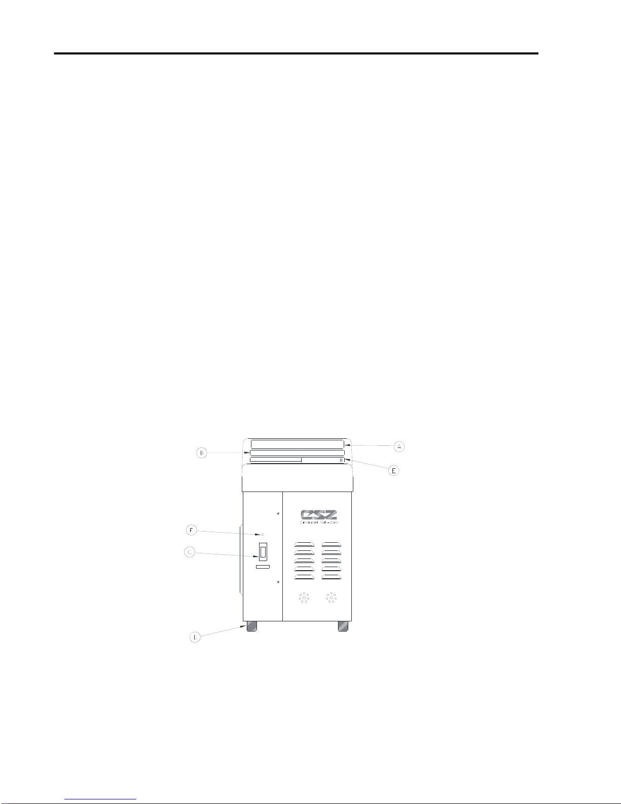
1-3.1. External Features and Descriptions –Front View
The external features in Figure 1 of the NORM-O-TEMP®unit are described as
follows:
A. The control panel is composed of pressure sensitive touch switches and an LED display.
An expanded description of the membrane control panel is presented in the
Operation/Technical Manual.
B. The operating instructions printed below the control panel describe the necessary steps
to operate the unit.
C. The power switch is a bevel rocker switch labeled “I” (on) at the top and “O” (off) at the
bottom.
D. The four rubber feet help the unit to mount on the I.V. stand (Catalog #118), the low
profile stand (Catalog #119) or allow the unit to sit on a flat surface.
E. The water fill opening is where the operator pours distilled water to fill the reservoir.
F. The red, Power Fail LED is the visual indicator when power is disconnected with the
switch still in its on position or when the independent mechanical (High Limit) safety is
activated.
Figure 1. NORM-O-TEMP®unit, Front View

Operation Manual NORM-O-TEMP, Model 111W
Page 13 of 26
1-3.2. External Features and Descriptions –Left Side View
The external features in Figure 2 of the NORM-O-TEMP®unit are described as
follows:
A. The water flow indicator is a paddle wheel immersed in the path of the circulating water
with a window to the outside. As water is circulated through the system, it must pass
over the paddle wheel causing it to spin (like a pinwheel). The water flow indicator
provides a visual display of the general rate at which the water is circulating. For
example, if the unit is circulating water but the connecting hose is pinched, the
circulation of the water is restricted. The change in water flow decreases the speed of the
paddle wheel. The water flow indicator only spins when a blanket/pad or by-pass hose is
connected to the unit. It will not spin when water is circulated internally to pre-condition
the water. A total obstruction of the water path will cause the paddle wheel to stop
completely.
B. Two screws on the left and right side of the unit secures the top to the base.
C. Two female Hansen fittings, quick-disconnect return couplings, on the top row are
designed for water to flow in when the male coupling of the connecting hose is attached.
D. Two male Hansen fittings, quick-disconnect outlet couplings, on the bottom row are
designed for water to flow out when the female coupling of the connecting hose is
attached.
E. The recessed handle, one on each side, is provided to assist in lifting the unit on and off
the I.V. stand or when carrying the unit.
Figure 2. NORM-O-TEMP®unit, Left Side View
Operation Manual NORM-O-TEMP, Model 111W
Page 14 of 26
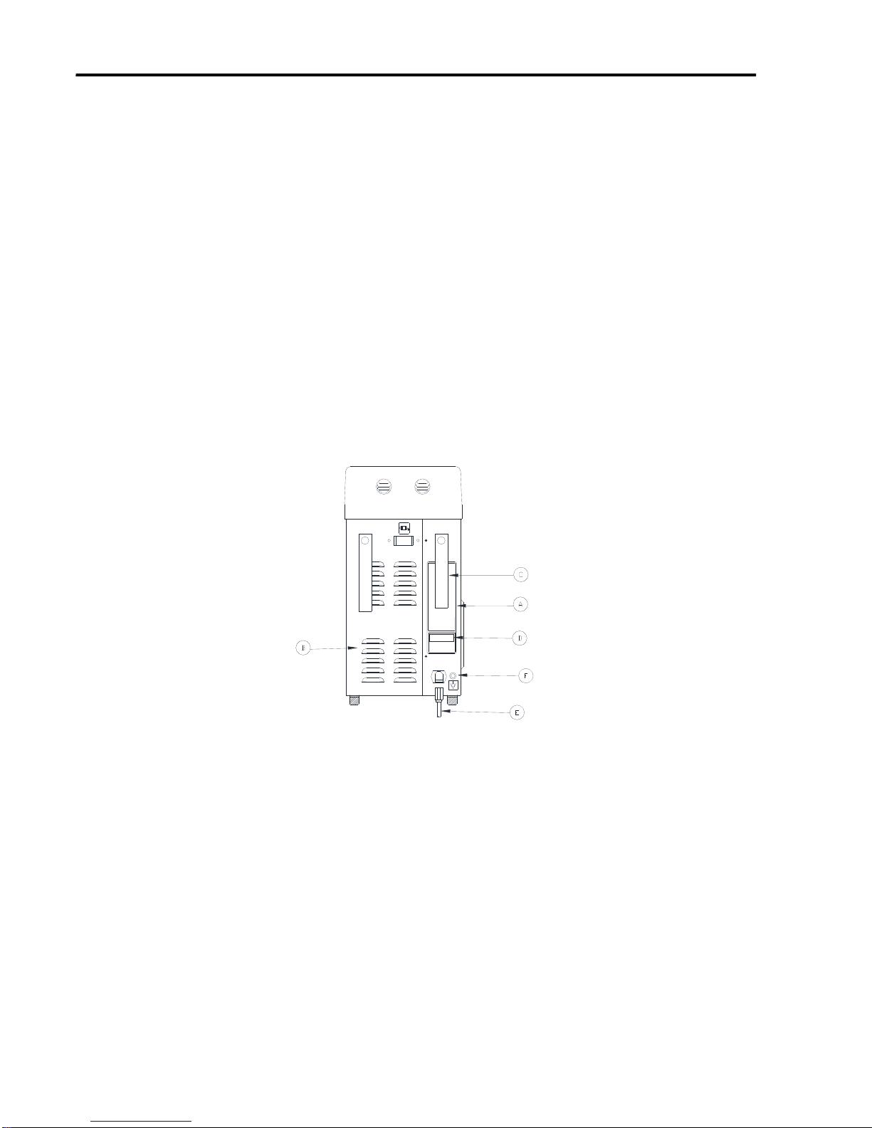
1-3.3. External Features and Descriptions –Rear View
The external features in Figure 3 of the NORM-O-TEMP®unit are described as follows:
A. The specification label outlines the NORM-O-TEMP®unit's electrical requirements.
B. Sets of air vents provide air circulation for the internal components.
C. The nylon straps are used to secure and store the coiled power cord and/or the connecting
hose when not in use.
D. The serial number printed on the Spec Label and located just above the power cord.
E. Units have a power cord that can be disconnected and should only be inserted into a
properly grounded mating receptacle of a hospital grade specified by local codes and
practices. Electrical specifications are described in Section 2-0.
F. Ground Lug
Figure 3. NORM-O-TEMP®unit, Rear View
Operation Manual NORM-O-TEMP, Model 111W
Page 15 of 26
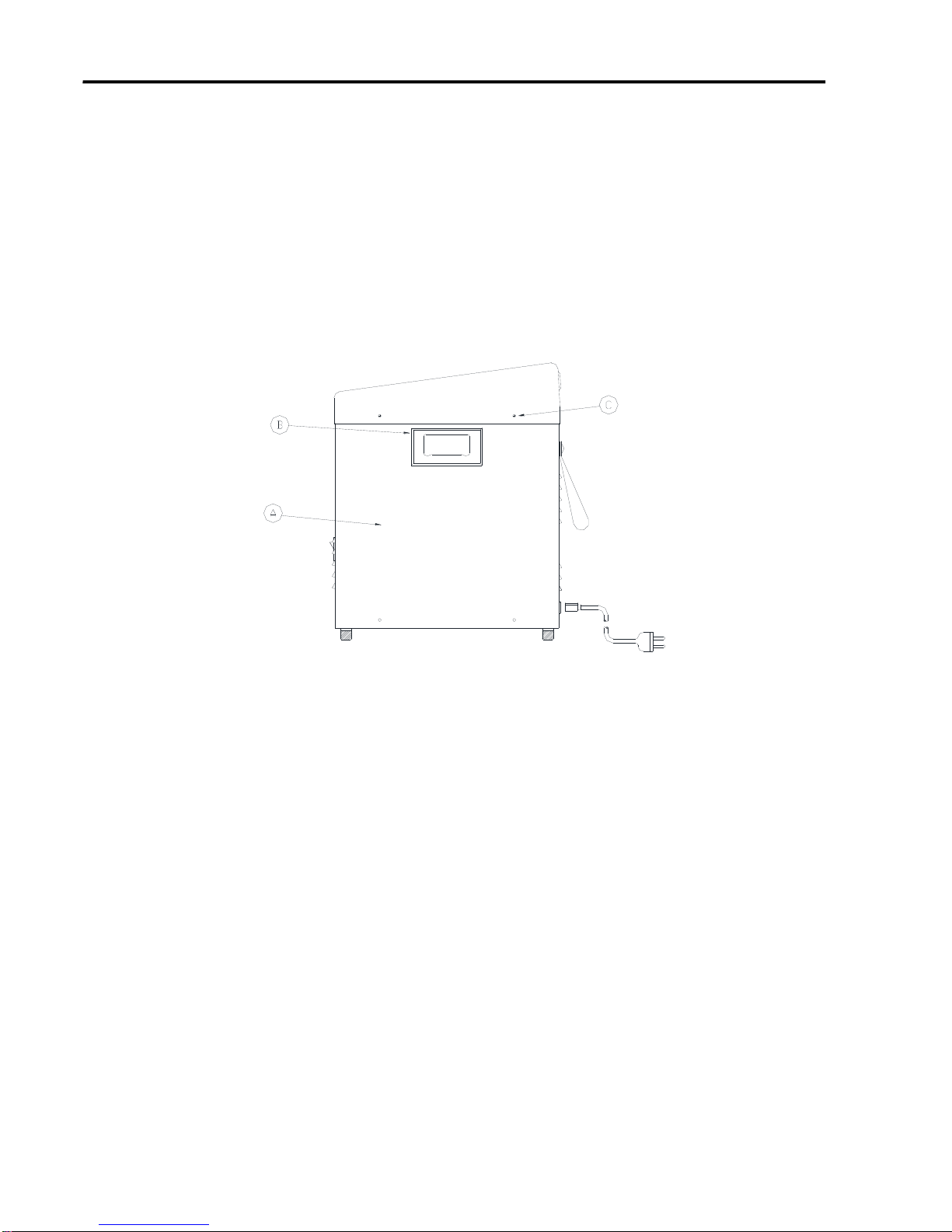
1-3.4. External Features and Descriptions –Right Side View
The external features in Figure 4 of the NORM-O-TEMP®unit are described as follows:
A. The three sided enclosure panel, secured with eight screws, provides access to the
interior.
B. The recessed handle is one of two provided to assist in lifting the unit.
C. Two screws on the right and left side of the unit secure the top to the base.
Figure 4. NORM-O-TEMP® unit, Right Side View
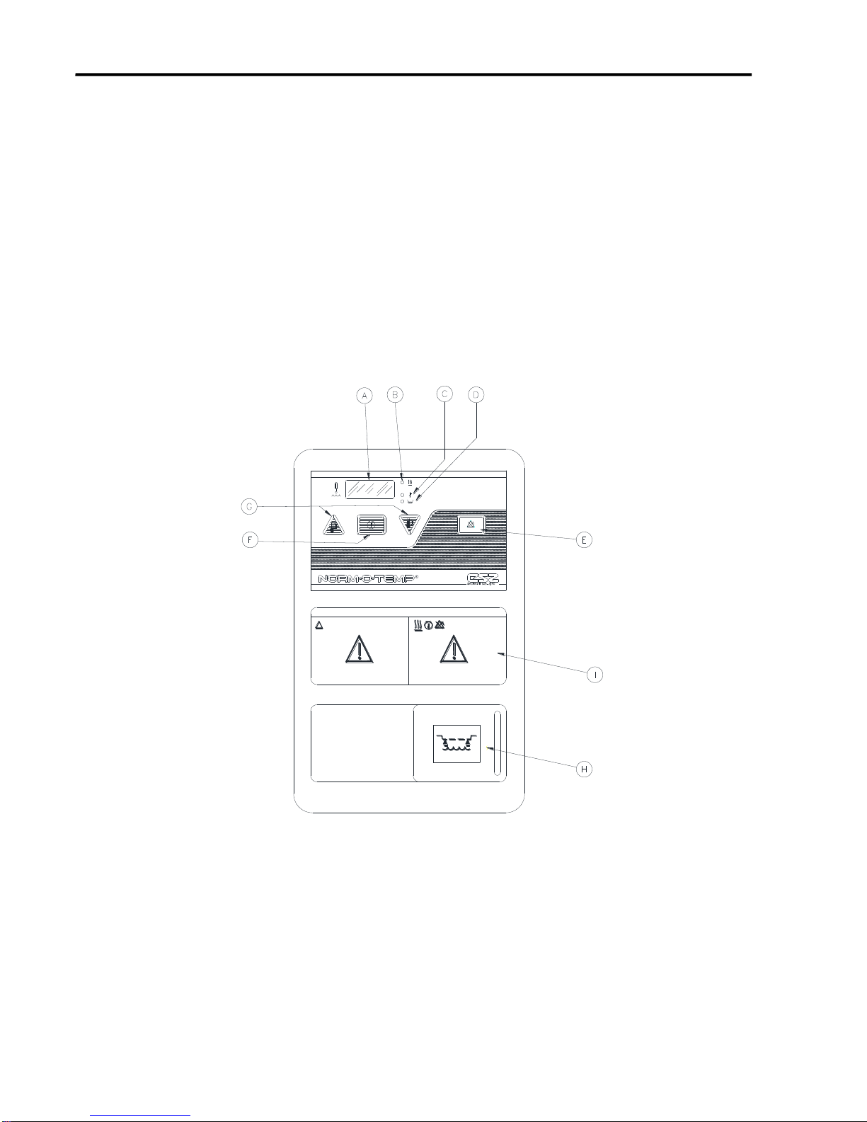
1-3.5. External Features and Descriptions –Top View
The membrane control panel as shown in Figure 5 is composed of pressure sensitive
touch switches and LED displays.
The membrane control panel is divided into the following sections:
A. The four digit LED display shows the actual water temperature and set point temperature.
B. When the HEAT LED is lighted, it indicates that the water is being heated.
C. The HI TEMP LED will illuminate, the power fail LED will illuminate, and the audible
alarm will sound when the water temperature reaches 46°C ±0.6°C. The HI TEMP LED
will flash when water temperature reaches 1°C ±0.6°C above the set point temperature.
D. When the LO WATER LED is lit it indicates that the unit needs more distilled water to
operate. The LED will be accompanied by an audible alarm.
Operation Manual NORM-O-TEMP, Model 111W
Page 16 of 26
E. The SILENCE ALARM button will silence the primary HI TEMP alarm and LO WATER
audible alarms for five minutes and if the problem is not solved, the alarm will sound
again until the button is pressed or the problem is solved.
F. The TEMP SET button is used to display and change the desired set point temperature.
When this button is pressed, the display will flash the set point temperature.
G. The INCREMENT and DECREMENT buttons are used to raise or lower the set point
temperature. The operator has less than ten (10) seconds to set the temperature up or
down after pressing the TEMP SET button.
H. The fill reservoir lid slides to the left to open and to the right to close.
I. Operating Instructions Label
Figure 5. NORM-O-TEMP® unit, Model 111W Top View.
Operation Manual NORM-O-TEMP, Model 111W
Page 17 of 26
1-4. Required Accessories
Operation of the NORM-O-TEMP®unit requires the use of the blanket/pad(s) designed to
circulate warm water via a connecting hose with quick-disconnect male and female couplings.
NORM-O-TEMP®System Equipment and accessories are listed in the Operation/Technical
Manual.
Note: Some reusable blankets/pads come with a permanently attached hose.
Section 2. Specifications and Certifications
Specifications for the NORM-O-TEMP®unit are presented in Figure 6 and are subject to change
without notice.
Physical
Dimensions:
22.86 cm Wide
38.14 cm Deep
46.99 cm High
Weight: 15.2 kg empty
20.6 kg filled
Ambient Temperature (during use):
15°C –30°C (59°F –86°F)
Cabinet Construction:
Powder-coated steel with plastic top. Dual
reservoir. Built-in handles.
Alarms
High Temperature:
Audible and Visual
Low Water:
Audible and Visual
Defective Water Temperature Sensor:
Audible and Visual
Water Flow Indicator:
Visual
Power Failure:
Audible and visual
Greater than 1° Over Set point:
Audible and Visual
Control System
Microprocessor-based temperature control
system, and Alarm indications.
Controller Range:
Water Temperature
Heating Only:
32°C - 42°C
Controller Accuracy:
Water Temperature: ±0.6°C
Display Range:
Water Temperature Display:
0°C - 52°C
Display Type:
LED Display.
Temperature Settings:
Water Temperature increments.
1°C
Service Life
The expected service life / lifetime of the
NORM-O-TEMP®, Model 111W unit is ten (10)
years from the date of manufacture provided the
product is not subject to misuse, negligence,
accident or abuse and under the conditions that
the device is properly used as intended, and
serviced and maintained according to the
Operation/Technical Manual provided with the
device.
Operation Manual NORM-O-TEMP, Model 111W
Page 18 of 26
Electrical System
Electrical Characteristics:
230V, 50Hz, 4.8 Amps
240V, 50Hz, 4.6 Amps
Heater Power:
800 watts
Time to Heat:
23°C ± 2°C to 37°C in approximately 7
minutes at ambient temperature.
Power Cord:
16/3 Detachable, IEC 320
Leakage Current:
Under 500µa 230/240 VAC
Fuse
5 Amp in IEC 320 connector
Mains Supply Isolation:
Two-Pole Mains Switch
Safety System
Maximum High Control Setting
42°C
Primary Temperature Limit:
43.5°C ± 0.6°C
Secondary Temperature Limit:
44.5°C ± 0.6°C
Independent Mechanical Temperature Limit:
46°C ± 0.6°C
Environmental Conditions
(during storage and transportation)
Ambient Temperature (transportation and
storage):
-40°C –+50°C
Humidity (transportation and storage):
20% –95%
Warranty
1 year parts. Parts and labor if returned to factory.
Additional Warranty Available
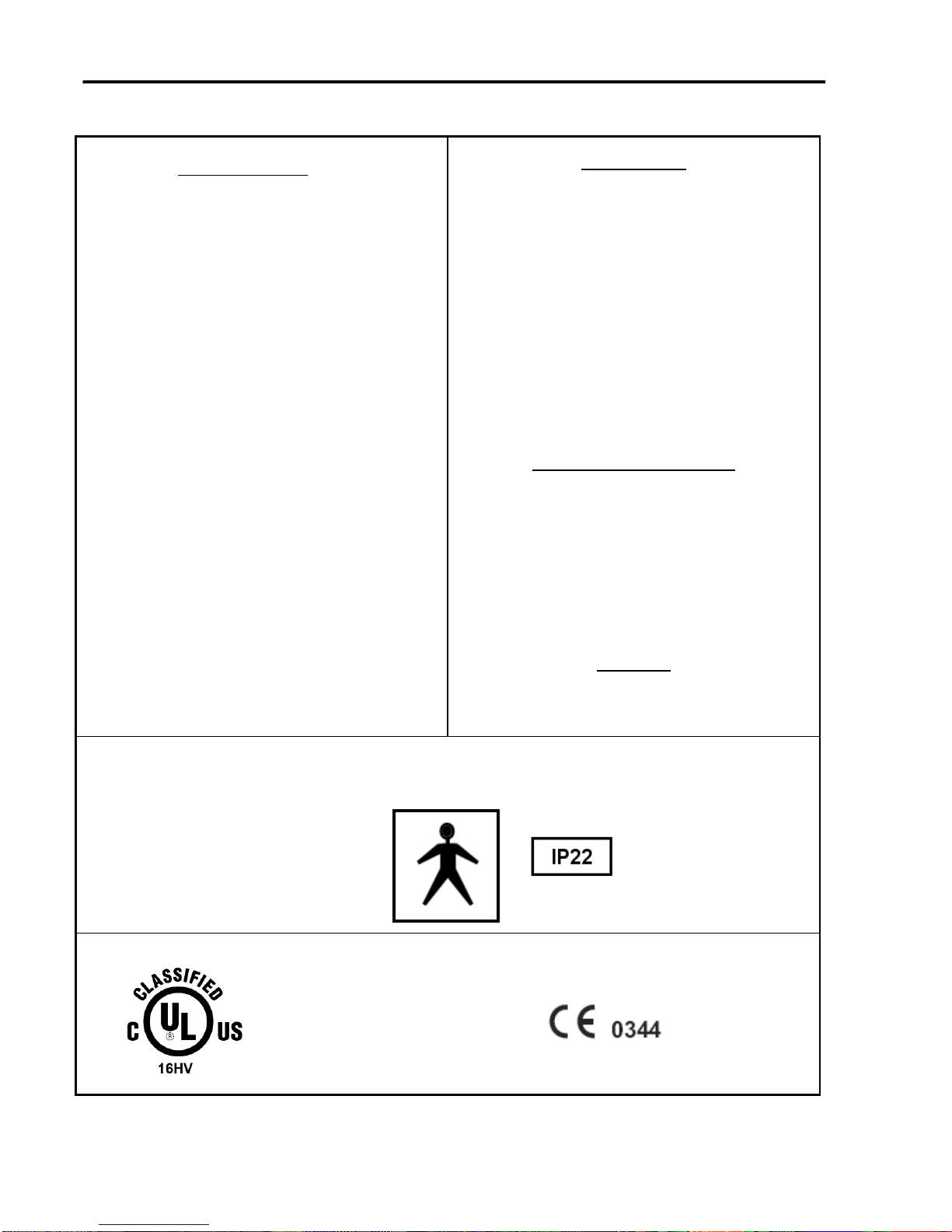
UL Electrical Classification
Equipment is Class I.
Equipment is Type BF.
CERTIFICATIONS
Figure 6. NORM-O-TEMP®unit, Model 111W Features
Medical Electrical
Equipment
In Accordance With:
UL 60601-1 2nd Ed.
IEC 60601-1-2 3rd Ed.
IEC 60601-1-6 3rd Ed.
ASTM F-2196-2

Operation Manual NORM-O-TEMP, Model 111W
Page 19 of 26
2-0. Unit and Patient Related Precautions
This unit requires both distilled water and electricity to operate.
NOTE: Please consult the beginning of the manual for a complete list of warnings and cautions
related to the NORM-O-TEMP®system.
2-1. Patient Preparation and Bedside Care
Effective use of the NORM-O-TEMP®hyperthermia system must include proper patient care prior
to and while using the hyper-hypothermia blanket/pad(s).
A. A base line recording should be made of vital signs, level of consciousness and
responsiveness.
B. It is recommended that a dry sheet be placed between the hyper-hypothermia
blanket/pad and the patient when using PLASTI-PAD, GELLI-ROLL, or MAXI-THERM
Blanket/pad(s).
Standard nursing procedures while using a hyper-hypothermia blanket/pad include the
following tasks:
A. Patient core temperature and the condition of the skin in contact with the blanket/pad and
blanket/pad water temperature should be checked every twenty minutes. Surgical
patients, temperature sensitive and pediatric patients should be checked more frequently.
Notify the physician if the patient's core temperature does not reach the prescribed
temperature in the time prescribed or deviates from the prescribed temperature range.
B. Changes in skin color, edema, inflammation, or indications of pressure, especially over
bony prominences, should be noted and treated as ordered. Avoid prolonged tissue
pressure and shearing forces over bony prominences.
C. The patient should be turned and properly positioned frequently.
2-2.Alarms and Error Displays
A. Power Failure Alarm
1. If power is removed from the unit without actuating the power switch (I/O
switch) a power fail alarm is activated and the LED located on the front panel
of the unit flashes.
2. If the Power Failure alarm occurs, turn the power switch off and unplug the
unit if it is not already unplugged. Then, plug the unit into the power source
and turn the power switch “ON”. If the Power Fail LED flashes and the audible
alarm continues to sound, remove the unit from service and send to
Biomedical Engineering for repair.
B. Low Water Alarm
1. If at anytime, the water in the reservoir falls below 1 ½ quarts (1.4 liters) a low
water level alarm will activate, the LO WATER LED located on the membrane
control panel will flash and the unit will shut down.
2. To clear the low water alarm, replenish the reservoir with distilled water as
described in Section 4-1.

Operation Manual NORM-O-TEMP, Model 111W
Page 20 of 26
C. Primary High Temperature Safety Alarm
1. If the circulating water reaches 43.5°C 0.6°C , the primary high temperature
safety will activate to turn off the pump and turn off heater. In addition, the HI
TEMP LED flashes and the audible alarm sounds.
2. If the primary high temperature alarm occurs, the unit should be powered off
and the power cord removed from the outlet. The unit should be immediately
removed from service and sent to Biomedical Engineering for repair.
D. Secondary High Temperature Safety Alarm
1. If the circulating water reaches 44.5°C ± 0.6°C, the secondary high temperature
safety will activate to turn off the pump and the heater. In addition, the HI
TEMP LED illuminates and the audible alarm sounds.
2. If the secondary high temperature alarm occurs, the unit should be powered off
and the power cord removed from the outlet. The unit should be immediately
removed from service and sent to Biomedical Engineering for repair.
E. Independent Mechanical High Temperature Safety Alarm
1. If the circulating water reaches 46°C ± 0.6°C the independent mechanical high
temperature safety will activate to shut off the power to the pump, shut off the
power to the heater, the HI TEMP LED and Power Fail LED illuminate, and the
trouble alarm sounds.
2. If the independent mechanical high temperature alarm occurs, the unit should
be powered off and the power cord removed from the outlet. The unit should
be immediately removed from service and sent to Biomedical Engineering for
repair.
F. 1°C Over Set point Alarm
1. If the set point temperature has been set at least 1°C lower than the actual
circulating water temperature, the 1°C Over Set point Temperature Alarm will
activate to turn off the heater, the HI TEMP LED flashes, the “WATER” display
flashes the actual water temperature and the trouble alarm sounds.
2. The heater will remain off, the HI TEMP LED will continue to flash and the
“WATER” display will continue to flash until the actual circulating water
temperature is within 1°C of the set point temperature. No additional action is
required.
G. Defective Water Temperature Sensor
1. If the “WATER” display reads “ERR” or “PF” the unit may have a defective
water temperature sensor.
2. If the “WATER” display reads “ERR” or “PF” the unit should be powered off and
the power cord removed from the outlet. The unit should be immediately
removed from service and sent to Biomedical Engineering for repair.
Table of contents
Other Cincinnati Sub-Zero Medical Equipment manuals

Cincinnati Sub-Zero
Cincinnati Sub-Zero WarmAir 135 User manual

Cincinnati Sub-Zero
Cincinnati Sub-Zero BLANKETROL III 233 User manual

Cincinnati Sub-Zero
Cincinnati Sub-Zero HEMOTHERM 400CE User manual

Cincinnati Sub-Zero
Cincinnati Sub-Zero ZP Series Instruction manual

Cincinnati Sub-Zero
Cincinnati Sub-Zero ELECTRI-COOL 757 User manual


