Cincinnati Sub-Zero BLANKETROL III 233 User manual

Operation and Technical Manual
Model 233 Hyper-Hypothermia System
Cincinnati Sub-Zero Products, LLC 12011 Mosteller Road Cincinnati, Ohio 45241, U.S.A.
www.cszmedical.com

OPERATION AND TECHNICAL MANUAL BLANKETROL III, Model 233
Page 2 of 131
BLANKETROL®is a registered trademark of Cincinnati Sub Zero Products LLC, Cincinnati, Ohio
USA.
©Copyright 2018, Cincinnati Sub-Zero Products, LLC. All rights reserved.
Manual 56201 Rev. AG
ECN: M1807-5495

OPERATION AND TECHNICAL MANUAL BLANKETROL III, Model 233
Page 3 of 131
Water
Temperature
Silence
Alarm
Temperature Set
Risk of Explosion:
Do not use in the
Presence of Flammable
Anesthetics
Danger; Risk of
Electric Shock
Disconnect Power
Before Servicing
Patient
Temperature
Automatic
Control
Manual
Control
Test Indicators
10C
Gradient 10˚ C
V
Gradient
Variable
5C
Smart
Mode
Water Flow
Indicator
Fill to Strainer
Outlet
Inlet
Low Water
Level
Power Failure
Symbol
Definitions
Read Operation
Instructions and Manual
Before Operating
Separate Disposal for
Electrical / Electronic
Equipment
Power Cord
Holder
Type BF
Equipment
ESD
Susceptibility
OFF / ON Switch
O / I
AC Voltage
~
USB Port: Insert Port
in This Direction
Monitor
Only
INCREMENT
(Increase
Temperature)
DECREMENT
(Decrease
Temperature)
Equipotential
Symbol
OFF/ON
OFF / ON Switch

OPERATION AND TECHNICAL MANUAL BLANKETROL III, Model 233
Page 4 of 131
BLANKETROL®III
OPERATION AND TECHNICAL MANUAL
Cincinnati Sub-Zero Products, LLC, reserves the right to make equipment changes and improvements, which
may not be reflected in this manual
WARNING
A physician's order is required for setting blanket temperature and use of equipment. At least every
20 minutes, or as directed by physician, check patient's temperature and skin integrity of areas in
contact with blanket; also, check the BLANKETROL III’s water temperature. Pediatric patients,
temperature-sensitive patients with vascular disease, surgical patients, diabetics and patients with
Raynaud’s Disease should be checked more frequently. Notify the physician promptly of any
change in patient status in order to avoid serious injury or death.
The method of temperature control provided by all hyper-hypothermia units presents the danger of
heating or cooling body tissues, particularly the skin, to a point where they are injured, i.e., burns or
frostbite, respectively. Depending on the extent and severity of a burn, very serious and even
fatal complications may arise.
Do not use the BLANKETROL III System distal to arterial cross clamping. Thermal injury may
result.
Thermal injury may occur if heating/cooling therapy is applied to ischemic limbs.
The warming of transdermal medications (patches) can increase drug delivery, resulting in
possible injury to the patient.
Prevent excessive and/or prolonged tissue pressure and shearing forces, especially over bony
prominences. Failure to do so may result in tissue injury.
Do not place additional heat sources between the patient and blanket. Tissue damage may result.
Means to maintain contact between the patient and the blanket during therapy may be required and
should not block the fluid pathways of the blanket or connecting hose. Failure to do so may result
in inadequate treatment.
Prep solutions have been reported to injure the skin when allowed to remain between patients
and a water-circulating heating blanket during prolonged procedures. Use of materials of good
thermal conductivity, such as water, gel, and similar substances, with the BLANKETROL III not
switched ON may decrease the temperature of the patient. The area between the patient and
the blanket should be kept dry to avoid injury to patient.
Proper sanitation procedures must be practiced and hygienic safety must be maintained, to prevent
contamination.Contamination can affect patient’s health, i.e. skin irritation/rash may result.
Use only YSI 400 Series, or equivalent, probes on CSZ equipment (refer to Table (6-8)). Failure to
do this will cause incorrect temperature readings and may result in inadequate/inappropriate
treatment.
Due to static electricity, a 400 Series Probe may not be connected to the BLANKETROL III unit
without first discharging one’s body to the frame of the BLANKETROL III unit or another grounded
object. Failure to do so may result in damage from electrostatic discharge (ESD). All staff
that may touch the 400 Series Probe must be familiar with this warning and basic static electricity
or electrostatic discharge (ESD) training.
Basic static electricity or ESD training should include an introduction to the physics of electrostatic
charge, the voltage levels that can occur in normal practice and the damage that can be done to
electronic components if equipment is touched by an operator who is electrostatically charged.
Further, an explanation should be given of methods to prevent build-up of electrostatic charge, and
how and why to discharge one’s body to the BLANKETROL III unit or another grounded object.
Failure to do so may result in damage from electrostatic discharge (ESD).

OPERATION AND TECHNICAL MANUAL BLANKETROL III, Model 233
Page 5 of 131
WARNING
Do not use the BLANKETROL III system in the presence of flammable anesthetics. Risk of
explosion can result.
Remove the BLANKETROL III from service if the outer casing or membrane control panel is cracked
or internal components are exposed. Contact with internal components could result in electric
shock or thermal injury to the patient or operator and exposure to sharp edges.
Keep grill and condenser clean and free of debris and obstruction. Blockage of the grill and
condenser could result in the unit overheating which could render the unit unable to provide
adequate therapy and excessive surface temperatures could cause injury of patient or
operator. Keep unit, specifically the grill away from curtains or other obstructions.
The USB connection on the BLANKETROL III unit is intended for data transfer to a computer. Any
other uses/connections may result in damage to the BLANKETROL III unit.
Working with electronic boards, plugs, and cables requires delicate handling. Proper electrostatic
discharge (ESD) procedures should be followed during replacement of any electronic board.
Failure to do so may result in damage to the board.
If unit requires repair, do not attempt to fix unit on your own. Only qualified personnel should perform
repairs. Damage to the unit or malfunction may otherwise result.
Use of accessories other than those specified in Table 6-8 may result in increased
electromagnetic emissions or decreased immunity to electromagnetic emissions of the
BLANKETROL III unit. This could affect the BLANKETROL III’s compatibility with other electrical
equipment. Electromagnetic compatibility refers to electronic devices unintentionally affecting the
operation of each other by emitting electromagnetic energy.
Power interruption will cause the BLANKETROL III to revert to CHECK SET POINT resulting in no
therapy to the patient. Follow instructions for desired mode to resume operation. Failure to resume
therapy could result in serious injury or death.
Do not by-pass ground lug (230V System). Electrical Hazards may result.
To avoid the risk of electric shock, this equipment must only be connected to a supply mains with
protective earth. Risk of electrical shock may occur.
Blanket punctures can result in an increased risk of infection or electrical shock. Inspect all
blankets for mechanical damage before use. Do not use in proximity to sharp objects.
Any time water is found leaking into or around the unit, connecting hose, and/or blanket, turn the
unit off, disconnect the power cord from its power source, and correct the problem before
proceeding. Proper maintenance procedures should be followed including, but not limited to, the
preventative maintenance described in this manual. Leaky blankets or hoses should never be
used. Water leaks could present a slip hazard and risk of infection and could lead to
electric shock.
Exercise extreme caution if the BLANKETROL III System is used on patients with cardiac issues,
for example, patients with pacemakers, or when a probe is inserted in or attached to the patient.
Failure to properly monitor patient may result in serious injury or death.
Due to electromagnetic compatibility, the BLANKETROL III unit should not be used adjacent to or
stacked with other equipment. Potential electromagnetic interference may result. Other
equipment includes ventilators, patient monitors, anesthesia delivery equipment, etc.
Electromagnetic interference refers to electronic devices unintentionally affecting the operation of
each other by emitting electromagnetic energy. Unit complies with IEC 60601-1-2.
If the BLANKETROL III unit or the other equipment is not operating normally, remove the device
from service and have a biomedical or service technician observe the device in operation. Refer
to Section 7 for recommended separation distances between other equipment and the
BLANKETROL III. Failure to do so may result in damage to the BLANKETROL III system
and patient injury.

OPERATION AND TECHNICAL MANUAL BLANKETROL III, Model 233
Page 6 of 131
WARNING
Always unplug the unit before accessing internal components during service. Failure to unplug
the unit could result in electric shock.
The repair, calibration, and servicing of the BLANKETROL III should be performed by qualified
Medical Equipment Service Technicians, Certified Biomedical Electronics Technicians, or Certified
Clinical Engineers familiar with good repair practices for servicing medical devices, and in
accordance with instructions contained in this manual. Improper repair can result in damage to
the BLANKETROL III system and patient injury.
No modification of this equipment is allowed without prior, written authorization from CSZ. Failure to
do so may result in damage to the BLANKETROL III system and patient injury.
Before returning the BLANKETROL III to patient use after repairs, the FIRST TIME SET-
UP/SYSTEM TEST ROUTINE in Section 2 must always be performed. Improper repair and
inadequate maintenance can result in damage to the BLANKETROL III system and patient
injury.

OPERATION AND TECHNICAL MANUAL BLANKETROL III, Model 233
Page 7 of 131
CAUTION
Federal law restricts this device to sale by or on the order of a physician.
Use distilled water only. Do Not Use De-Ionized water. De-Ionized water may cause corrosion
to plumbing system components. Do Not Use Tap Water. Minerals and deposits can clog
plumbing system components.
Do not use alcohol. Alcohol may cause blanket and unit deterioration.
Use only hospital grade plug or electric shock may result.
Do not overfill. Overfilling may result in overflow when the water in the blanket drains back into the
system when the system is turned off.
Always drain the BLANKETROL III to a sanitary drain because bio-contaminants may be present in
the unit’s water supply.
Handling or use of the patient probe may result in damage from electrostatic discharge (ESD) if
proper precautions are not taken.
All wire-lead, patient-connected transducer assemblies are subject to reading error, local heating,
and possible damage from high intensity sources of RF energy. Inadequately grounded
electrosurgical equipment represents one such source, since capacitively coupled currents may seek
alternate paths to ground through probe cables and associated instruments. Patient burns may
result. If possible, remove the probe from patient contact before activating an electrosurgical unit.
Do not immerse probes or connecting cables in liquid. Failure to do so may result in damage to the
probes.
If the unit was shipped on its side, permit the unit to rest in an upright position for twelve (12) hours
before operating due to refrigeration oil displacement.
For safe handling and use of chemicals follow manufacturer guidelines.
Do not make any connection to the USB port terminal while the device is also connected to a patient.
Do not touch this connector and the patient at the same time. Patient injury may result.
Users should not use cleaning or decontamination methods different from those recommended by
CSZ without first checking with CSZ that the proposed methods will not damage the equipment.
Working with electronic boards, plugs, and cables requires delicate handling. Proper electrostatic
discharge (ESD) procedures should be followed during replacement of any electronic board.
Failure to do so may result in damage to the board.
If device is set to operate in any Automatic mode, the device will shut down and activate the CHECK
PROBE alarm if the patient temperature falls below 30.0°C (86°F). Patient temperature must rise
above 30.0°C (86°F) before restarting the device in Automatic mode. The device can be operated in
Manual Control mode in order to warm the patient above 30.0°C (86°F). Potential for interruption of
therapy.
Unapproved blankets or hoses should never be used.

OPERATION AND TECHNICAL MANUAL BLANKETROL III, Model 233
Page 8 of 131
Table of Contents
TECHNICAL HELP ..................................................................................................................................................11
BEFORE YOU CALL FOR SERVICE....................................................................................................................11
IN-WARRANTY REPAIR AND PARTS ...............................................................................................................11
RECEIVING INSPECTION .....................................................................................................................................11
IMPORTANT SAFETY INFORMATION .............................................................................................................. 11
SECTION 1. INTRODUCTION...............................................................................................................................12
1-0. GENERAL SAFETY PRECAUTIONS..................................................................................................... 12
1-1. GENERAL DESCRIPTION OF THIS MANUAL .................................................................................... 12
1-2. GENERAL DESCRIPTION OF THE BLANKETROL III SYSTEM....................................................... 12
1-3. PHYSICAL DESCRIPTION OF THE BLANKETROL III UNIT ............................................................ 14
1-3.1. External Features - Front View ............................................................................................................ 14
1-3.2. External Features –Right Side View .................................................................................................... 16
1-3.3. External Features –Rear View.............................................................................................................18
1-3.4. Description of the BLANKETROL III Membrane Control Panel ......................................................... 20
1-4. REQUIRED ACCESSORIES.................................................................................................................... 22
1-5. FUNCTIONAL DESCRIPTION OF THE BLANKETROL III SYSTEM ................................................ 22
1-5.1. Theory of Operation.............................................................................................................................. 22
1-5.2. Heating System ..................................................................................................................................... 23
1-5.3. Cooling System ..................................................................................................................................... 24
1-5.5. Temperature Safety Control System...................................................................................................... 24
1-5.6. USB Port Operation.............................................................................................................................. 26
SECTION 2. GENERAL PREPARATION OF THE BLANKETROL III SYSTEM.........................................27
2-1. INTRODUCTION.....................................................................................................................................27
2-2. UNPACKING THE SHIPMENT............................................................................................................... 27
2-3. FIRST TIME SET-UP/SYSTEM TEST ROUTINE ..................................................................................27
2-3.1. Inspecting and Arranging the Equipment ............................................................................................. 27
2-3.2. Completing a System Test Routine........................................................................................................ 29
2-4. UNIT AND PATIENT RELATED PRECAUTIONS................................................................................ 36
2-5. PATIENT PREPARATION AND BEDSIDE CARE................................................................................ 37
SECTION 3. OPERATING THE BLANKETROL III SYSTEM.........................................................................41
3-1. INTRODUCTION.....................................................................................................................................41
3-2. ARRANGING THE SYSTEM COMPONENTS....................................................................................... 41
3-3. OPERATING THE BLANKETROL III SYSTEM IN AUTO CONTROL MODE ....................................44
3-4. OPERATING THE BLANKETROL III SYSTEM IN MANUAL CONTROL MODE............................... 47
3-5. OPERATING THE BLANKETROL III SYSTEM IN MANUAL CONTROL MODE WITH THE
ADDITION OF THE PATIENT PROBE.................................................................................................. 49
3-6. OPERATING THE BLANKETROL III SYSTEM IN GRADIENT 10C MODE....................................... 50
3-7. OPERATING THE BLANKETROL III UNIT IN GRADIENT 10C SMART MODE................................ 53
3-8. OPERATING THE BLANKETROL III SYSTEM IN GRADIENT VARIABLE MODE............................ 55
3-9. OPERATING THE BLANKETROL III SYSTEM IN GRADIENT VARIABLE SMART MODE .............. 58
3-10. OPERATING THE BLANKETROL III SYSTEM IN MONITOR ONLY MODE ..................................... 61
3-11. CONCLUDING HYPER-HYPOTHERMIA TREATMENT.................................................................... 62
3-12. STATUS DISPLAY MESSAGES............................................................................................................. 63
SECTION 4. GENERAL MAINTENANCE OF THE BLANKETROL III SYSTEM .......................................71
4-1. INTRODUCTION.....................................................................................................................................71

OPERATION AND TECHNICAL MANUAL BLANKETROL III, Model 233
Page 9 of 131
4-1.1. TEST EQUIPMENT REQUIRED ......................................................................................................... 72
4-2. MAINTENANCE OF THE WATER RESERVOIR..................................................................................74
4-2.1. Draining the Reservoir ......................................................................................................................... 77
4-2.2. Replenishing the Reservoir ................................................................................................................... 78
4-3. MAINTENANCE OF THE WATER FILTER .......................................................................................... 78
4-4. MAINTENANCE OF THE CONDENSER AND GRILL......................................................................... 80
4-5. MAINTENANCE OF THE BLANKETROL III EXTERIOR –CLEANING INSTRUCTIONS..............80
4-6. MAINTENANCE OF THE HYPER-HYPOTHERMIA BLANKETS...................................................... 80
4.6.1 Reusable Blanket................................................................................................................................... 80
4-6.2. Disposable, Single-Patient Use Blankets.............................................................................................. 81
4-7. MAINTENANCE OF REUSABLE THERMISTOR PROBES................................................................. 81
4-8. LOW LIMIT SAFETIES CHECK............................................................................................................. 82
4-9. HIGH LIMIT SAFETIES CHECK ............................................................................................................ 83
4-10. TEMPERATURE ACCURACY CHECK................................................................................................. 84
SECTION 5. FIELD REPAIR/SERVICE OF THE BLANKETROL III UNIT..................................................85
5-1. INTRODUCTION.....................................................................................................................................85
5-2. ACCESS TO THE INTERIOR OF THE BLANKETROL III UNIT.......................................................... 88
5-2.1. Removing the Rear Enclosure Panel..................................................................................................... 88
5-2.2. Removing the Top of the Unit ...............................................................................................................88
5-2.3. Removing the Left Side Enclosure Panel .............................................................................................. 89
5-2.4. Disconnecting the Cables from the Microprocessor Board.................................................................. 89
5-2.5. Extending the Front Storage Drawer....................................................................................................90
5-2.6. Repositioning the Front Storage Drawer.............................................................................................. 90
5-3. REPLACEMENT OF THE HEATER .......................................................................................................91
5-4. REPLACEMENT OF THE WATER FILTER ASSEMBLY.....................................................................91
5-5. REPLACEMENT OF THE PUMP HOUSING.......................................................................................... 92
5-6. REPLACEMENT OF THE PUMP MOTOR............................................................................................. 93
5-7. REPLACEMENT OF THE FLOW SWITCH............................................................................................ 95
5-8. REPLACEMENT OF THE WATER TEMPERATURE SENSOR........................................................... 96
5-9. REPLACEMENT OF THE UPPER AND/OR LOWER WATER MANIFOLDS.....................................97
5-10. REPLACEMENT OF THE COMPRESSOR STARTING CAPACITOR, THE OVERLOAD
PROTECTOR, AND/OR THE COMPRESSOR RELAY......................................................................... 98
5-11. REPLACEMENT OF THE THERMAL DISC OVER TEMPERATURE DEVICE ................................. 99
5-12. REPLACEMENT OR CLEANING OF THE WATER FLOW INDICATOR ASSEMBLY..................... 99
5-13. REPLACEMENT OF THE I/O POWER SWITCH................................................................................. 101
5-14. REPLACEMENT OF THE WATER LEVEL SENSOR ASSEMBLY.................................................... 101
5-15. REPLACEMENT OF THE MICROPROCESSOR BOARD AND/OR THE MEMBRANE CONTROL
PANEL.................................................................................................................................................... 102
5-16. REPLACEMENT OF THE BEEPER ASSEMBLY ................................................................................ 103
5-17. REPLACEMENT OF THE POWER CORD ........................................................................................... 104
5-18. LEAKAGE CURRENT........................................................................................................................... 104
5-18.1. Arranging the Equipment............................................................................................................. 104
5-18.2. Taking Measurements in Normal Polarity ................................................................................... 105
5-18.3. Taking Measurements in Reverse Polarity................................................................................... 105
5-19. REFRIGERANT CHECK ....................................................................................................................... 105
5-20. TROUBLESHOOTING GUIDE ............................................................................................................. 106
SECTION 6. PARTS INFORMATION................................................................................................................. 115
6-1. INTRODUCTION...................................................................................................................................115
6-2. ORDERING INFORMATION FOR REPLACEMENT PARTS............................................................. 115
6-3. RECOMMENDED REPLACEMENT PARTS INVENTORY ............................................................... 115
6-4. RETURNING PARTS UNDER WARRANTY....................................................................................... 116
6-5. SHIPPING PARTS.................................................................................................................................. 116
SECTION 7. SPECIFICATIONS AND CERTIFICATIONS OF THE BLANKETROL III........................... 127
WORLDWIDE ORDER PLACEMENT................................................................................................................ 131

OPERATION AND TECHNICAL MANUAL BLANKETROL III, Model 233
Page 10 of 131
FIGURES AND TABLES
FIGURE 1-1. BLANKETROL III - FRONT VIEW.............................................................................................................15
FIGURE 1-2. BLANKETROL III - RIGHT SIDE...............................................................................................................17
FIGURE 1-3. BLANKETROL III - REAR VIEW...............................................................................................................19
FIGURE 1-4.A. BLANKETROL III - MEMBRANE CONTROL PANEL (ENGLISH)....................................................21
FIGURE 1-4.B. BLANKETROL III - MEMBRANE CONTROL PANEL (SYMBOLS)...................................................21
FIGURE 4-1. BLANKETROL III MAINTENANCE CHECKLIST ...................................................................................73
FIGURE 5-1. BLANKETROL III - EXPOSED REAR VIEW ............................................................................................87
FIGURE 6-1. PARTS LIST A............................................................................................................................................117
FIGURE 6-2. BLANKETROL III - INTERNAL EXPLODED - FRONT VIEW..............................................................118
FIGURE 6-3. PARTS LIST B ............................................................................................................................................119
FIGURE 6-4. BLANKETROL III - INTERNAL EXPLODED - REAR VIEW................................................................120
FIGURE 6-5.A. BLANKETROL III - ELECTRICAL WIRING DIAGRAM - 115 VOLT ..............................................121
FIGURE 6-5.B. BLANKETROL III - ELECTRICAL WIRING DIAGRAM - 230 VOLT...............................................122
FIGURE 6-6. BLANKETROL III - WATER CIRCULATION DIAGRAM.....................................................................123
FIGURE 6-7. BLANKETROL III - REFRIGERATION FLOW DIAGRAM ...................................................................124
TABLE 6-8. BLANKETROL III SYSTEM ACCESSORIES............................................................................................125
TABLE 7-1. GUIDANCE AND MANUFACTURER'S DECLARATION - ELECTROMAGNETIC EMISSIONS.......129
TABLE 7-2. GUIDANCE AND MANUFACTURER'S DECLARATION - ELECTROMAGNETIC IMMUNITY.......129
TABLE 7-3. GUIDANCE AND MANUFACTUERER'S DECLARATION - ELECTROMAGNETIC IMMUNITY.....130
TABLE 7-4. RECOMMENDED SEPARATION DISTANCES BETWEEN PORTABLE AND MOBILE RF
COMMUNICATIONS EQUIPMENT AND THE BLANKETROL III, MODEL 233................................131

TECHNICAL HELP BLANKETROL III, Model 233
OPERATION AND TECHNICAL MANUAL
Page 11 of 131
TECHNICAL HELP
United States and Canada Telephone 1-513-772-8810
Cincinnati Sub-Zero Products, LLC (U.S.) Toll Free 1-800-989-7373
12011 Mosteller Road (U.S.) 24hr Clinical Support 1-513-460-2038
Cincinnati, OH 45241 Fax 1-513-772-9119
www.cszmedical.com
Authorized European Representative:
CEpartner4U, BV
Esdoornlaan 13
3951 DB Maarn
The Netherlands
www.CEpartner4U.com
BEFORE YOU CALL FOR SERVICE...
To help us better serve you, please have the serial number of your BLANKETROL III unit ready
when you call for parts or service. The serial number is located on a specification label attached
to the unit’s rear panel.
How to read serial numbers:
Example: 121-3-60000
12 indicates a manufacturing date of the year 2012
1 indicates the quarter (first)
-3- means BLANKETROL III, Model 233
60000 indicates that this is the 60,000th unit of a certain model
IN-WARRANTY REPAIR AND PARTS
All parts on your BLANKETROL III unit are covered by a two-year (2) warranty. Additional third
year warranty is available at the time of purchase. To return defective parts or units, first obtain
a Returned Materials Authorization (RMA) number from our Medical Technical Service
department. All returns should be made using CSZ-issued shipping cartons.
RECEIVING INSPECTION
After unpacking the BLANKETROL III System, be sure to inspect the system for concealed
damage. Retain all packing material and carefully describe or photograph any damage. Notify
the carrier at once and ask for an inspection (in writing). Failure to do this within 15 days may
result in loss of claim. Do not return the equipment to Cincinnati Sub-Zero. Call our Medical
Technical Service department for further instructions.
IMPORTANT SAFETY INFORMATION
Refer to this manual for instructions and operator information. Read and understand all
WARNINGS / CAUTIONS before using, prescribing, or servicing the BLANKETROL III System.

OPERATION BLANKETROL III, Model 233
OPERATION AND TECHNICAL MANUAL
Page 12 of 131
SECTION 1. INTRODUCTION
1-0. GENERAL SAFETY PRECAUTIONS
To provide the patient maximum safety during the use of the BLANKETROL III System, a thorough
knowledge and understanding of the system, and its correct application and operating use are
required. Each person who is responsible for use or direction of use of the system, such as
physicians, nurses, technicians and operators must read and understand this operating manual and
all precautions and warnings prior to use. It is recommended this manual be read at least semi-
annually as a refresher for safe operation and application. For proper knowledge and
understanding, in-service is available upon request.
1-1. GENERAL DESCRIPTION OF THIS MANUAL
This manual describes the operation, maintenance, and service of the CSZ BLANKETROL III
System. Section one describes the physical and functional characteristics of the BLANKETROL III
System. Section two describes how to prepare the BLANKETROL III System for general use.
Section three describes how to operate the unit in the MANUAL CONTROL MODE, AUTO
CONTROL MODE, GRADIENT 10C MODE, GRADIENT 10C SMART MODE, GRADIENT
VARIABLE MODE, GRADIENT VARIABLE SMART MODE,and MONITOR ONLY MODE. Section
four describes the regular maintenance of the BLANKETROL III unit. Section five describes Field
Repair and Service of the BLANKETROL III unit and contains a troubleshooting guide. Section six
outlines parts information and section seven lists the specifications of the BLANKETROL III.
This manual is prepared for professional personnel who use the BLANKETROL III for patient care
as well as technicians and service personnel who are responsible for maintaining the equipment. All
personnel who operate or service the unit should be familiar with all parts of this manual. However,
Sections one, two, and three are primarily intended for personnel who unpack and setup the unit.
Section three is primarily intended for personnel who operate the unit, and Sections three through
six are primarily intended for personnel who service and repair the unit. Section (1-3.) describes the
external features of the BLANKETROL III and Section (3-12.) describes display messages. These
sections should be consulted if questions arise over the terminology used in this manual.
Operating modes are described in Section (1-5.1.) and are highlighted throughout the manual in
italics and capital letters. Button names and display messages are shown in all capital letters.
1-2. GENERAL DESCRIPTION OF THE BLANKETROL III SYSTEM
INDICATIONS FOR USE
The BLANKETROL III Hyper-Hypothermia Temperature Management System is used to lower or
to raise a patient’s temperature and/or maintain a desired patient temperature through conductive
heat transfer. The system is composed of a heater, a compressor, a circulating pump and
blankets/pads.
BLANKETROL III Model 233
This unit requires no field adjustments or calibrations in order to maintain the precise board
measurement of temperature
and temperature limits.

OPERATION BLANKETROL III, Model 233
OPERATION AND TECHNICAL MANUAL
Page 13 of 131
Distilled water is heated or cooled and pumped from the unit to a blanket. The blanket* rests under
and/or on top of the patient and is designed so that the water circulates through the blanket and
returns to the unit.
If water that is at a lower temperature than the patient’s temperature is circulated through the
blanket, the desired effect is to reduce the patient's temperature. If water that is at a higher
temperature than the patient’s temperature is circulated through the blanket, the desired effect is to
elevate the patient's temperature.
The BLANKETROL III unit can be set so that it operates based on the temperature of the water in
the BLANKETROL III equipment (MANUAL CONTROL MODE) or it can be set so that it operates
based upon the patient’s temperature (Automatic Modes). The five Automatic modes include:
1) AUTO CONTROL MODE
2) GRADIENT 10C MODE
3) GRADIENT 10C SMART MODE
4) GRADIENT VARIABLE MODE
5) GRADIENT VARIABLE SMART MODE
The BLANKETROL III System can also be used solely to monitor the temperature of the patient
(MONITOR ONLY MODE).
The BLANKETROL III is intended for use in ambient temperatures of 15°C –30°C (59°F –86°F).
The maximum contact surface temperature is 41°C (105.8°F).
* The recommended blanket(s) for use are described in Table 6-8.

OPERATION BLANKETROL III, Model 233
OPERATION AND TECHNICAL MANUAL
Page 14 of 131
1-3. PHYSICAL DESCRIPTION OF THE BLANKETROL III UNIT
See Section (7.) for specifications and certifications of the BLANKETROL III.
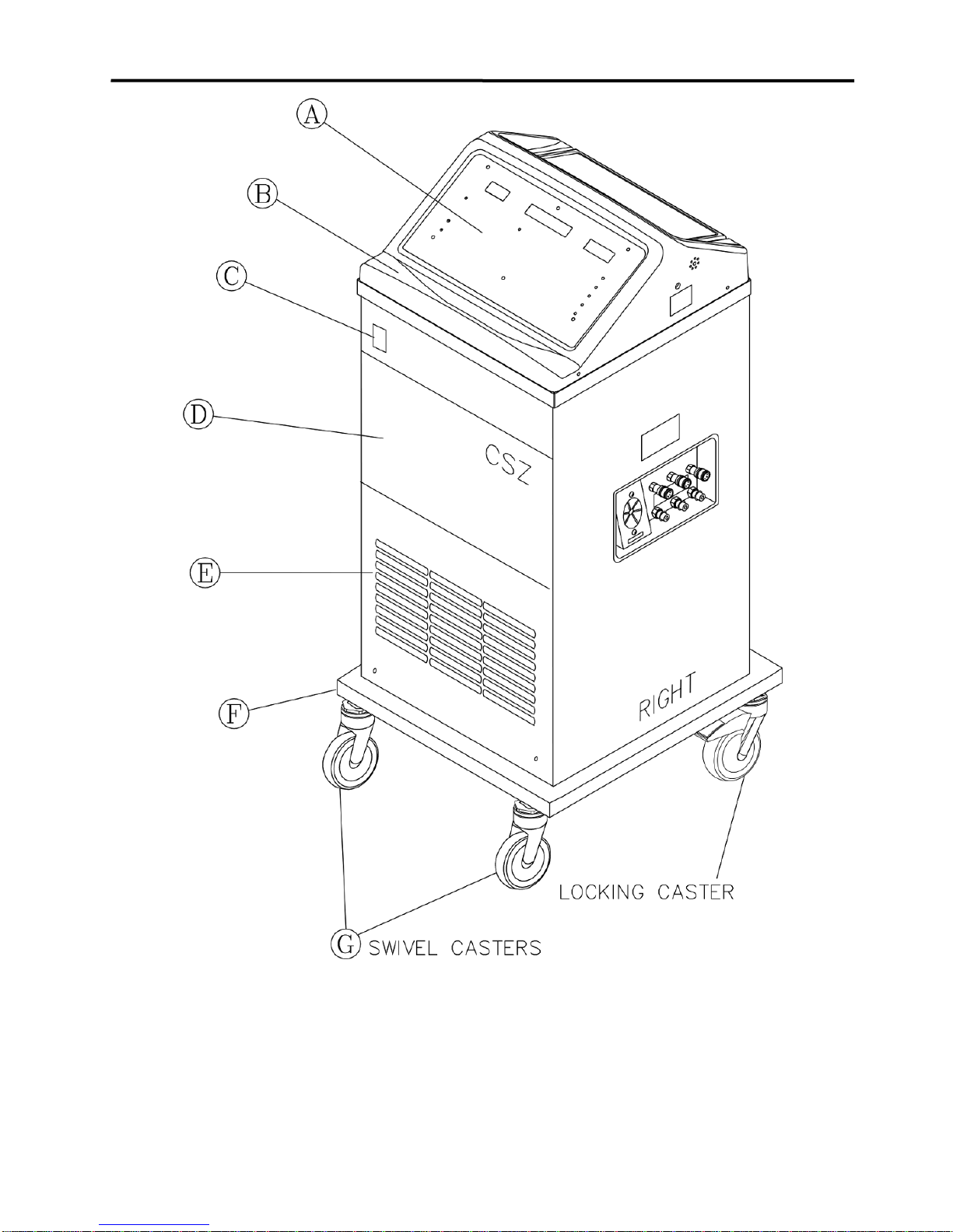
1-3.1. External Features - Front View
The external features in Figure (1-1.) of the BLANKETROL III unit are described as follows:
A. The control panel is composed of pressure sensitive touch switches, nine LED
indicators, a liquid crystal display, and two LED displays. An expanded description of
the membrane control panel is presented in Section (1-3.4.).
B. The recessed handle permits the operator to grip the unit when moving it.
C. The power switch is a bevel rocker switch labeled “I” (on) at the top and “O” (off) at the
bottom. The switch illuminates green when the unit is on. A circuit breaker is built into
the switch to protect against overload conditions.
D. The storage drawer tilts out from the top to provide storage space for items such as
probes, connecting cables, connecting hoses, the drain hose, and the Operator's
Manual.
E. The grill permits air to be drawn into the unit and pass over the condenser. The air is
then discharged through the bottom of the unit. The grill and compressor should be
kept clear from blockage and cleaned regularly as described in Section (4-4.).
F. The protective bumper guard surrounds the lower edge of the unit and protects the
unit as well as the walls.
G. Four swivel casters are specially designed to permit the unit to move easily and to
prevent it from tipping. The unit is equipped with two locking casters to prevent
unintended movement during operation.
OPERATION BLANKETROL III, Model 233
OPERATION AND TECHNICAL MANUAL
Page 15 of 131
FIGURE 1-1. BLANKETROL III - FRONT VIEW

OPERATION BLANKETROL III, Model 233
OPERATION AND TECHNICAL MANUAL
Page 16 of 131
1-3.2. External Features –Right Side View
The external features in Figure (1-2.) of the BLANKETROL III unit are described as follows:
A. The water flow indicator is a paddle wheel immersed in the path of the circulating
water with a window to the outside. As water is circulated through the system, it
passes over the paddle wheel causing it to spin (like a pinwheel). The water flow
indicator provides a visual display of the general rate at which the water is circulating.
For example, if the unit is circulating water but the connecting hose is pinched, the
circulation of the water is restricted. The restriction in water flow decreases the speed
of the paddle wheel.
The water flow indicator only spins when a blanket or by-pass hose is connected to the
unit. It will not spin while the water is being circulated internally to pre-condition the
water to the ‘preset” water temperature chosen by the operator.
A total obstruction of the water path will cause the paddle wheel to stop completely.
B. The air vents, on both the right and left side of the unit, provide air circulation for the
microprocessor.
C. The four capped screws on the right and left side of the unit secure the top to the base.
D. The patient 1/4 inch receptacle is where the 400 Series probe (refer to Table 6-8 for a
list of temperature probes) is connected to the unit. Only one patient probe can be
connected at a time.
E. Three female, quick-disconnect return fittings on the top row are designed for water to
flow in when the male coupling of the connecting hose is attached.
F. The three male quick-disconnect outlet fittings on the bottom row are designed for
water to flow out when the female coupling of the connecting hose is attached.
G. The power cord with a hospital-grade plug should only be plugged into a properly
grounded hospital grade receptacle. Electrical Specifications are described in Section
(7.).
H. The isolation label indicates that the BLANKETROL III and the blanket (applied part)
are BF rated as a system. Contact with other parts (i.e. the quick-disconnect fittings) at
the same time as contacting the patient will negate the type of BF rating.

OPERATION BLANKETROL III, Model 233
OPERATION AND TECHNICAL MANUAL
Page 17 of 131
FIGURE 1-2. BLANKETROL III - RIGHT SIDE

OPERATION BLANKETROL III, Model 233
OPERATION AND TECHNICAL MANUAL
Page 18 of 131
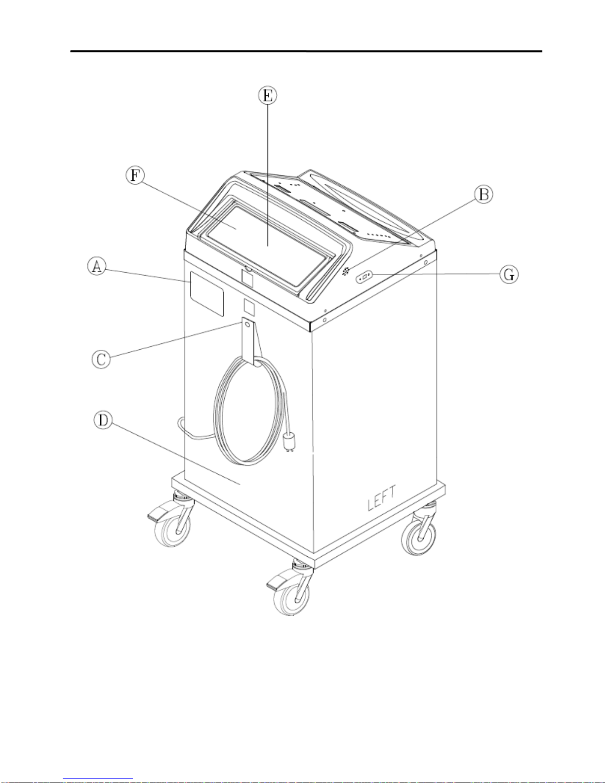
1-3.3. External Features –Rear View
The external features in Figure (1-3.) of the BLANKETROL III unit are described as follows:
A. The specification label outlines the BLANKETROL III unit's electrical requirements and
displays the serial and model numbers of the unit.
B. The air vents, on both the right and left side of the unit, provide air circulation for the
microprocessor.
C. The nylon strap is used to secure and store the coiled power cord when not in use.
D. The rear enclosure panel secured with four screws provides access to the interior.
The panel is removed to perform maintenance, repair, or replacement of components.
E. The water fill opening is where the operator pours distilled water into the unit to fill the
reservoir.
F. The operating instructions are printed directly on the back lid of the unit. This allows
the operator to clearly see the directions and efficiently use the unit.
G. The USB port for data reporting functions.
OPERATION BLANKETROL III, Model 233
OPERATION AND TECHNICAL MANUAL
Page 19 of 131
FIGURE 1-3. BLANKETROL III - REAR VIEW

OPERATION BLANKETROL III, Model 233
OPERATION AND TECHNICAL MANUAL
Page 20 of 131
1-3.4. Description of the BLANKETROL III Membrane Control Panel
The membrane control panel as shown in Figure (1-4.A.) for English and (1-4.B.) for Symbols is
composed of pressure sensitive touch switches and LED displays.
The membrane control panel is divided into the following sections:
A. The green LED display labeled WATER shows the water temperature in the
BLANKETROL III equipment.
B. The MANUAL CONTROL button is used to activate the MANUAL CONTROL
MODE. This mode’s operation is based on the water temperature within the
BLANKETROL III equipment relative to the desired Set Point temperature.
C. The green LCD display reports the status of the unit, displays the Set Point, and/or
indicates changes the operator should make. It is referred to as the Status Display.
The possible Status Displays are listed in Section (3-12.).
D. The TEMP SET button and the Up and Down arrow buttons are used to adjust the
Set Point as shown on the LCD display.
E. The green LED display, labeled PATIENT, shows the patient’s temperature reading.
F. The AUTO CONTROL button is used to activate the AUTO CONTROL MODE. In
this mode the operation is based on the patient’s temperature relative to the desired
Set Point temperature.
G. The GRADIENT 10C button is used to activate the GRADIENT 10C MODE. In this
mode the operation is based on the patient’s temperature relative to the Set Point
temperature.
H. The GRADIENT VARIABLE button is used to activate the unit GRADIENT
VARIABLE MODE. In this mode the operation is based on the patient’s temperature
relative to the desired Set Point temperature.
I. The SMART button is used to activate the SMART function in the appropriate
modes.
J. The MONITOR ONLY button is used to monitor the patient’s temperature without
heating, cooling or circulating the water.
K. The two switches labeled TEST INDICATORS and SILENCE ALARM are used to
confirm that all the indicators on the membrane control panel are working and to
silence the alarm in certain conditions.
L. The POWER FAILURE symbol flashes the red LED to the left of the symbol and
sounds an audible alarm when the unit loses power or when power has been
interrupted, restored, and the unit does not resume previous operation.
M. The LOW WATER symbol indicates the unit is low on water. The unit flashes the
red LED to the left of the symbol, sounds an audible alarm, and displays ”LOW
WATER” in the Status Display. Refer to Section (3-12-D. Low Water).
N. The C/F Button allows the operator to select the measurement scale, Celsius or
Fahrenheit, by which the unit functions. This feature is only available on units with
an English membrane.
Table of contents
Other Cincinnati Sub-Zero Medical Equipment manuals

Cincinnati Sub-Zero
Cincinnati Sub-Zero ZP Series Instruction manual

Cincinnati Sub-Zero
Cincinnati Sub-Zero HEMOTHERM 400CE User manual

Cincinnati Sub-Zero
Cincinnati Sub-Zero WarmAir 135 User manual

Cincinnati Sub-Zero
Cincinnati Sub-Zero ELECTRI-COOL 757 User manual

Cincinnati Sub-Zero
Cincinnati Sub-Zero NORM-O-TEMP Installation manual
Popular Medical Equipment manuals by other brands


Getinge
Getinge Arjohuntleigh Nimbus 3 Professional Instructions for use

Mettler Electronics
Mettler Electronics Sonicator 730 Maintenance manual

Pressalit Care
Pressalit Care R1100 Mounting instruction

Denas MS
Denas MS DENAS-T operating manual

bort medical
bort medical ActiveColor quick guide

AccuVein
AccuVein AV400 user manual


