cinetto B-MOVED User manual

1Assembly Instructions CinettoB-moved.
1. Initial condition of the wardrobe
Do not plug the control unit to electricity before connecting all the engines (see connections at pages 4-5-
6-7).
Connect all the electric motors of the transmission bars to the control unit according to the wardrobe con guration.
After connecting all the electric motors to the control unit close manually all the doors.
2. Control unit power supply
After connecting all the
electric motors to the
control unit and after closing
manually all the doors is
possible to connect the
control unit to the power
supply.
After connecting to the power supply, wait at least 10 seconds, to allow to the control unit to
check the wardrobe con guration.
3. Self-learning cycle
Start the self-learning cycle to make the
automatic set-up of the run of the doors
pressing at least 3 seconds the “SET /
RESET” button on the power unit. All the
doors, one by one, starting from the rst left
door on the wardrobe, will move at reduced
speed until their nal stoppers.
This operation, until all the doors record their
run, may take some minutes.
During the self-learning cycle do not
stop or put obstacles towards the doors
and keep the door’s run free.
If the position of the nal stoppers
is modi ed, please repeat the self-
learning cycle again.
Quick start installation and setup
00:00:10
SET/
RESET
00:00:03

2 3Assembly Instructions CinettoB-moved.
6. General check of the system
Check that the movement of the doors work properly.
Check the safety system against accidental crush, putting an obstacle between the door while closing and the side
of the furniture.
Make this check to prevent danger or damage determined by a wrong operation of the system.
SOURCE
DEVICE
DEVICEDEVICE
0 - 48
N/O
SWITCH
During the self-learning cycle the pairing with the remote control is not working.
If the self-learning cycle is not working, because of lack if electricity or for the presence of obstacles disconnect
from the power supply, close manually the doors and start the self-learning cycle again.
4. Pairing of the remote control
To activate the pairing function, press and
release the “REMOTE SET” button on the
control unit. Then a red LED will ash
on the control unit. While the LED
is ashing, press for at least 3
seconds one of the buttons of
the remote control to pair it.
Multiple control units
can be paired and used
with a single remote
control.
Multiple remote controls
can be paired and used
with the same control
unit.
Pairing must not be activated
during the track memorization
cycle.
To unpair the remote control unit, press and release the
“REMOTE SET” button, after which the red LED will ash.
Press the “REMOTE SET” button again and keep it pressed
until the led stops ashing. When the button is released, the
red LED will ash 5 times to con rm the unpairing.
The unpairing of a remote control completely eliminates its
association with any control unit. In order to use the remote
control, it will be necessary to pair it again using the standard
procedure.
5. Wiring of the switch on the control unit
The N.O. switch is a normally-opened electric contact, managed by the
control unit.
There is no electric tension on the terminals of the switch. The switch isn’t
a voltage supply.
The switch can manage devices with nominal tension between 0
and 48V and a maximum electric current of 2A.
The wiring between the switch and the devices must be performed
by specialized personnel according to the following scheme.
REMOTE
SET
00:00:03
FREQUENCY: 433,92 MHZ
MAX POWER: 1 mW
DEVICE = 0 - 48V
MAX 2A
SWITCH
N/O
O
I
SOURCE
DEVICE
DEVICE
0 - 48V
MAX 2A
N/O
SWITCH

4 5Assembly Instructions CinettoB-moved.
Wardrobe confi gurations with coplanar doors PS40 & B-MOVED
CONNECTIONS
11
1 4
ALWAYS
SYNCHRONIZED
1 2 3 4
S
S
32
S
E
G
F
A
S = synchronized

6 7Assembly Instructions CinettoB-moved.
Wardrobe confi gurations with overlapping doors PS48 & B-MOVED
CONNECTIONS
122
1
1 3
2
C
B
*Central door opening just
to the left.
32
S
F
1 4
2 3
ALWAYS
SYNCHRONIZED
S
S
G
S = synchronized

8 9Assembly Instructions CinettoB-moved.
1
1
Confi gurations for retractable doors PS66 & B-MOVED
CONNECTIONS
A
11
S
B
S = synchronized

10 11Assembly Instructions CinettoB-moved.
23
S
BConfi gurations for vertical concealed doors PS70 & B-MOVED
CONNECTIONS
1
S = synchronized

12 13Assembly Instructions CinettoB-moved - Wave Sensor.
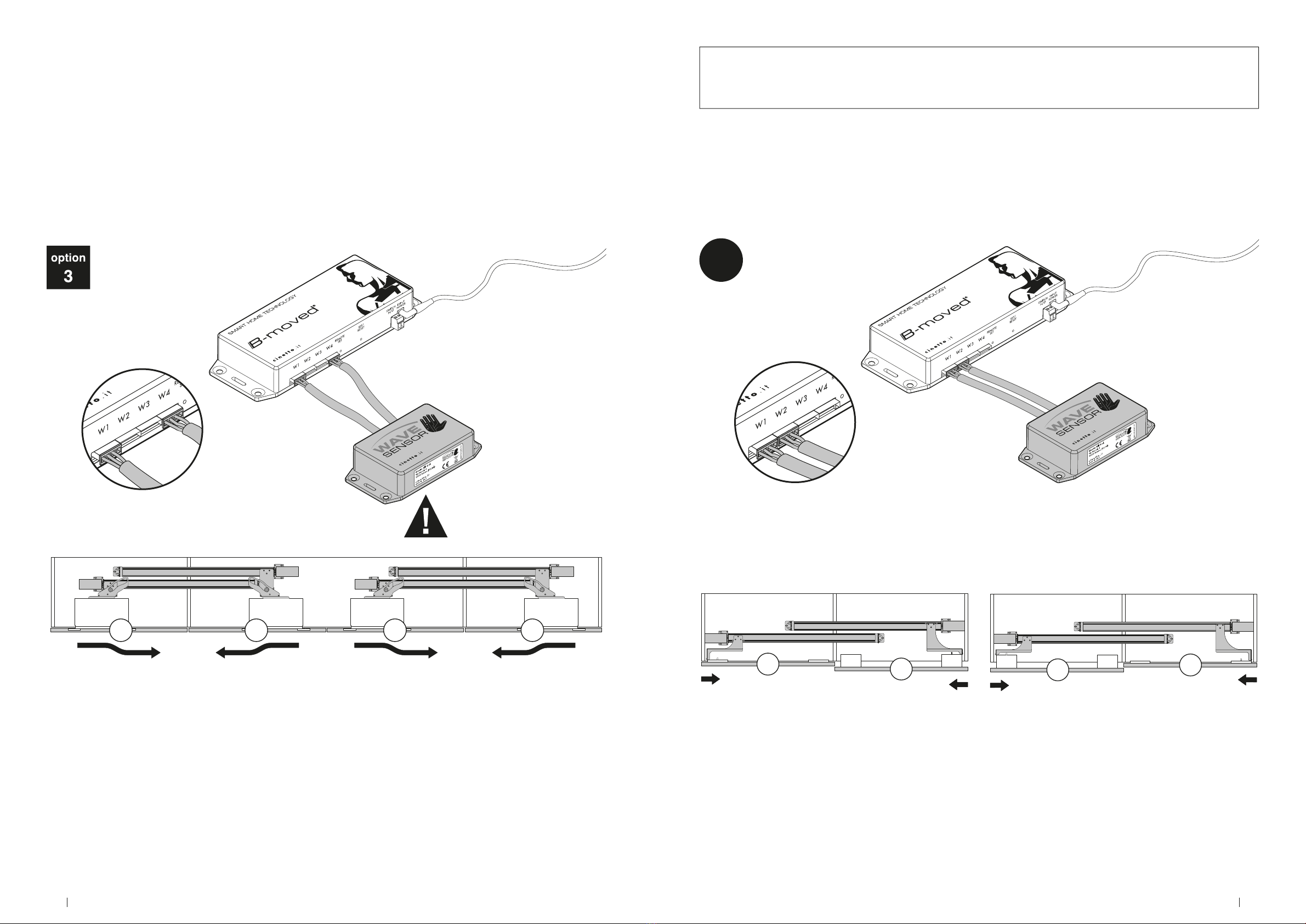
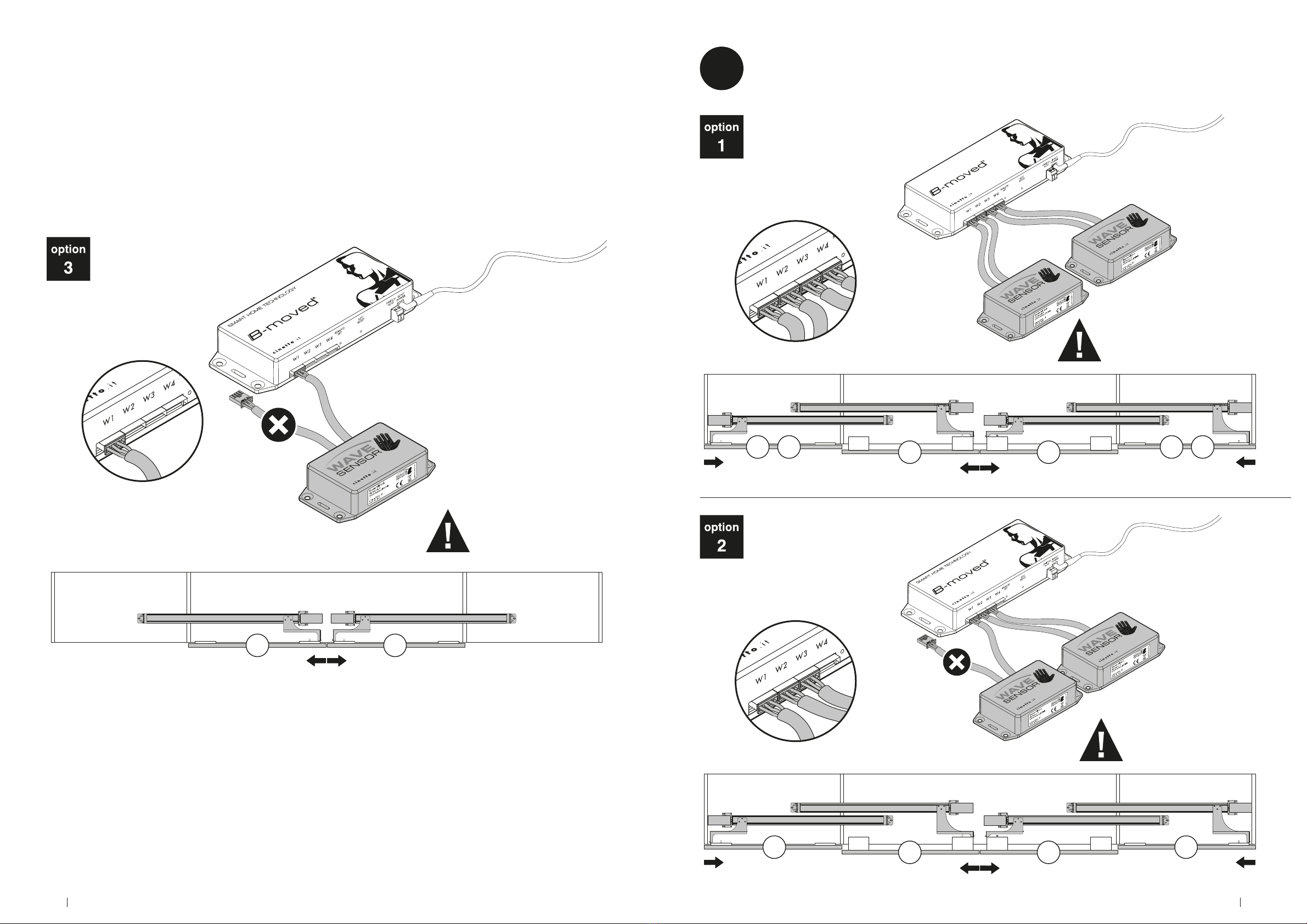
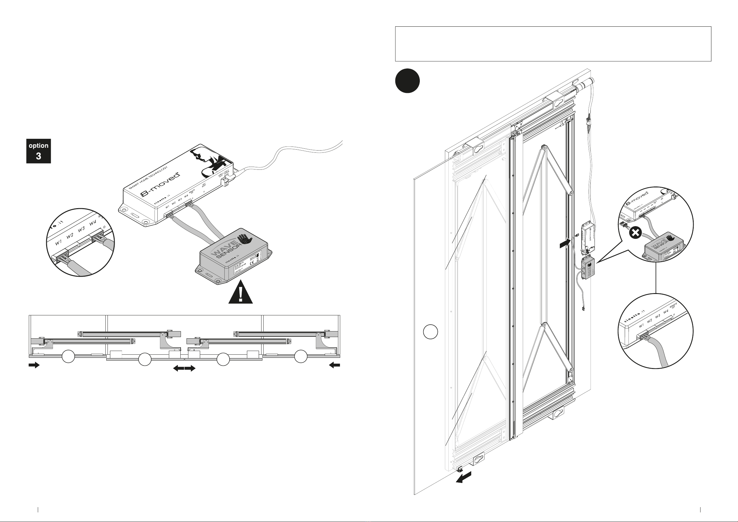
Before installing Wave Sensor, it is necessary to have installed the B-moved electrical system.
PS40 & B-MOVED
W1 W1
ACONFIGURATION

14 15Assembly Instructions CinettoB-moved - Wave Sensor.
W3W2
W3W1W2 W1
FCONFIGURATION
W1 = synchronized opening
W1 W4
ECONFIGURATION

16 17Assembly Instructions CinettoB-moved - Wave Sensor.
W2 W4 W1 W1 W4 W3
W2 W1 W1 W3
GCONFIGURATION
W1, W4 = synchronized opening
W1 = synchronized opening
W1W1
W1 = synchronized opening
18 19Assembly Instructions CinettoB-moved - Wave Sensor.
W1 W2 W2
W1
B
PS48 & B-MOVED
CONFIGURATION
W4 W1 W1 W4
W1, W4 = synchronized opening

20 21Assembly Instructions CinettoB-moved - Wave Sensor.
W1 W3
W2
C
*Central door opening just to the left.
CONFIGURATION
W3W1W2 W1
FCONFIGURATION
W3W2
W1 = synchronized opening
22 23Assembly Instructions CinettoB-moved - Wave Sensor.
W1W1
W1 = synchronized opening
W2 W4 W1 W1 W4 W3
W2 W1 W1 W3
GCONFIGURATION
W1, W4 = synchronized opening
W1 = synchronized opening
24 25Assembly Instructions CinettoB-moved - Wave Sensor.
W4 W1 W1 W4
W1, W4 = synchronized opening
PS66 & B-MOVED
W1
ACONFIGURATION

26 27Assembly Instructions CinettoB-moved - Wave Sensor.
W1
W1
BCONFIGURATION
W1 = synchronized opening W1 = synchronized opening
W1
W1

28 29Assembly Instructions CinettoB-moved - Wave Sensor.
PS70 & B-MOVED
W1
Wireless proximity sensor
Up to 10 sensors each
door.
Max recommended distance between receiver unit and sensor: 10 meters.
Battey not included.
2 x AAA 1,5V for each sensor.

30 31Assembly Instructions CinettoB-moved - Wave Sensor.
Wave Sensor positioning
3821
71,5
23
option
MAX 10 MAX 10 MAX 10
Do not place Wave Sensor behind metallic, conductive materials or mirrors.
102
68,5 5
00:00:02
1. Pairing
To start the procedure, press and hold the button for the channel you want to con gure (“SENSOR SET A”
or “SENSOR SET B”) for two seconds, the corresponding LED will start to ash.

32 33Assembly Instructions CinettoB-moved - Wave Sensor.
2. Reset
To reset a channel, press and hold the corresponding button for 10 seconds. The LED will start to ash and
then remain steady for two seconds. Once it stops ashing, the reset procedure is completed and it will be
possible to pair again to the channel up to a maximum of 10 sensors.
Touch the sensor you want to pair, this will be immediately recognised, causing the LED to ash quickly
twice before turning off. At this point the procedure is completed and the devices are correctly paired.
• Up to 10 different sensors can be paired with each channel.
• The receiver remains in the “pairing” phase for 30 seconds. If no sensor is touched during this
time, the procedure is blocked.
• If you try to pair a sensor already paired to the channel, the LED will ash quickly twice and
then block the procedure.
• If nothing happens, this means that either there is a system malfunction or the maximum
number of sensors that can be paired with the channel has been reached. Try resetting the
channel (see point 2) and repeat the pairing.

34 35Assembly Instructions CinettoB-moved - Wave Sensor.
English
All dimensions in this leaet are stated in
millimeters.
WARNING
Do not use any anti-friction oil or grease
or thread-realese spray on ball bearing or
on wheels with O-ring, it can cause the
melting of the inside ball bearing grease,
making them noisy or causing the break
of the O-ring of the wheels.
ABBREVIATIONS
W width
WA door width
L length
LB rail length
D depth
H height
I distance between centres
T thickness
S overlapping
The pictures and descriptions this leaet
contains are supplied for information
purposes. The company reserves the
right to introduce those modications it
deems opportune for any construction or
commercial need at any time and without
advance notice.

7th edition - NOVEMBER 2021
Cinetto F.lli S.r.l.
Via Rossi, 5/A
35030 Rubano (PD) Italy
Tel. +39 049 8977211
Fax +39 049 635822
www.cinetto.it
This article is part of the B-MOVED electrical system for opening and
closing the cabinet doors.
It must be installed following the original instructions inside the
package brackets for xing the upper slides to the B-MOVED system.
Code: PS40KM10002P0002, PS48KM10002P0001,
PS48KM10002P0002, PS48KM10003P0001, PS66KE70020001,
PS66KE70020002, PS70KE70020001.
This manual suits for next models
7
Other cinetto Control System manuals


