CIPRIANI SSA 07 User manual

SSA - Istruzioni Operative - EN-IT_rev4
EN - IT
11,1+2,35*N (8,75+2,35*N)
0,965+0,062*N (0,881+0,062*N)
11,1+2,35*N (8,75+2,35*N)
1,293+0,089*N (1,182+0,089*N)
14,95+2,35*N (12,6+2,35*N)
1,811+0,128*N (1,661+0,128*N)
14,83+2,29*N (12.54+2,29*N)
2,338+0,13*N (2.168+0.13*N)
14,83+2,29*N (12,54+2,29*N)
3,024+0,186*N (2,798+0,186*N)
15,9+2,35*N (13,55+2,35*N)
8,505+0,389*N (6,983+0,389*N)
OPERATIVE INSTRUCTIONS
ISTRUZIONI OPERATIVE
SSA 07 - SSA 09
SSA 62 - SSA 82
SSA X2
BRAZED PLATE
HEAT EXCHANGERS
SCAMBIATORI A PIASTRE
SALDOBRASATE

2
EN
11,1+2,35*N (8,75+2,35*N)
0,965+0,062*N (0,881+0,062*N)
11,1+2,35*N (8,75+2,35*N)
1,293+0,089*N (1,182+0,089*N)
14,95+2,35*N (12,6+2,35*N)
1,811+0,128*N (1,661+0,128*N)
14,83+2,29*N (12.54+2,29*N)
2,338+0,13*N (2.168+0.13*N)
14,83+2,29*N (12,54+2,29*N)
3,024+0,186*N (2,798+0,186*N)
15,9+2,35*N (13,55+2,35*N)
8,505+0,389*N (6,983+0,389*N)
ENGLISH
CONTENT
ENGLISH ...............................................................................................................................2
MAXIMUM APPLICABLE CATEGORY BY MODEL..............................................................3
1. PRELIMINARY CAUTIONS................................................................................................4
2. INTRODUCTION................................................................................................................4
3. MATERIAL DELIVERY.......................................................................................................4
4. HANDLING AND TRANSPORTATION ..............................................................................4
5. INSTALLATION .................................................................................................................6
6. USE....................................................................................................................................8
7. MAINTENANCE AND USER CHECKS ..............................................................................8
8. SAFETY .............................................................................................................................9
9. DISPOSAL .......................................................................................................................10
3
EN
11,1+2,35*N (8,75+2,35*N)
0,965+0,062*N (0,881+0,062*N)
11,1+2,35*N (8,75+2,35*N)
1,293+0,089*N (1,182+0,089*N)
14,95+2,35*N (12,6+2,35*N)
1,811+0,128*N (1,661+0,128*N)
14,83+2,29*N (12.54+2,29*N)
2,338+0,13*N (2.168+0.13*N)
14,83+2,29*N (12,54+2,29*N)
3,024+0,186*N (2,798+0,186*N)
15,9+2,35*N (13,55+2,35*N)
8,505+0,389*N (6,983+0,389*N)
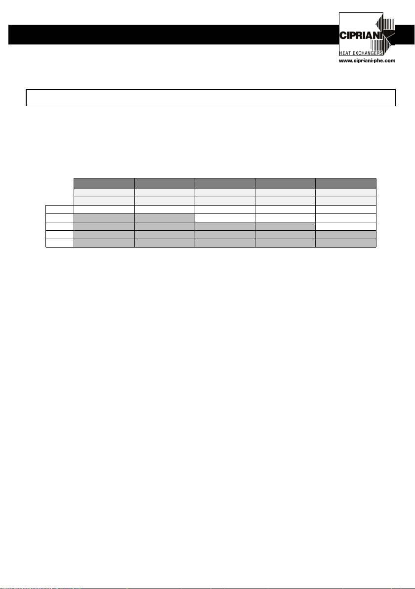
MAXIMUM APPLICABLE CATEGORY BY MODEL
The CIPRIANI PHE SRL plate heat exchangers can be used as single-phase heat
exchangers (gas/gas).
The following charts report the PED category pertaining to each type of exchanger,
calculated at maximum allowed pressure for each model.
SSA 07 SSA 09 SSA 62 SSA 82 SSA X2
PS=16bar PS=16bar PS=16bar PS=16bar PS=16bar
Fluid Gr.2 - G Fluid Gr.2 - G Fluid Gr.2 - G Fluid Gr.2 - G Fluid Gr.2 - G
Art. 4.3 0-120 0-120 0-80 0-50 0-22
Cat.I 82-120 52-150 24-92
Cat.II 94-240
Cat.III
Cat.IV
Group 2 fluids are usable.
For other fluids, please contact CIPRIANI PHE SRL.

4
EN
11,1+2,35*N (8,75+2,35*N)
0,965+0,062*N (0,881+0,062*N)
11,1+2,35*N (8,75+2,35*N)
1,293+0,089*N (1,182+0,089*N)
14,95+2,35*N (12,6+2,35*N)
1,811+0,128*N (1,661+0,128*N)
14,83+2,29*N (12.54+2,29*N)
2,338+0,13*N (2.168+0.13*N)
14,83+2,29*N (12,54+2,29*N)
3,024+0,186*N (2,798+0,186*N)
15,9+2,35*N (13,55+2,35*N)
8,505+0,389*N (6,983+0,389*N)
1. PRELIMINARY CAUTIONS
These Operator Instructions must be kept in good preservation conditions, in a place easily
accessible to the appointed personnel. These Operator Instructions are not exempt from
compliance with the laws in force regarding safety and on-the-job injury protection
regulations. CIPRIANI PHE SRL SHALL NOT BE LIABLE in the case of:
improper use of equipment under pressure;
alterations of the equipment under pressure;
non-compliance with safety regulations in force;
non-compliance with the content of these Operator Instructions.
2. INTRODUCTION
The plate exchangers are composed of a pile of corrugated plates, stacked onto each other
between two closure plates. The pile of plates is subjected to a process of brazing with the
forming of two separate circuits.
3. MATERIAL DELIVERY
Before carrying out any operation on the exchanger, check the correspondence between the
ordered machine and the received one. Please also verify that the model of the exchanger
has been adequately sized with the CIPRIANI PHE SRL selection programme for the type of
application.
3.1 Enclosed documents
These Operator Instructions are always enclosed with the exchanger.
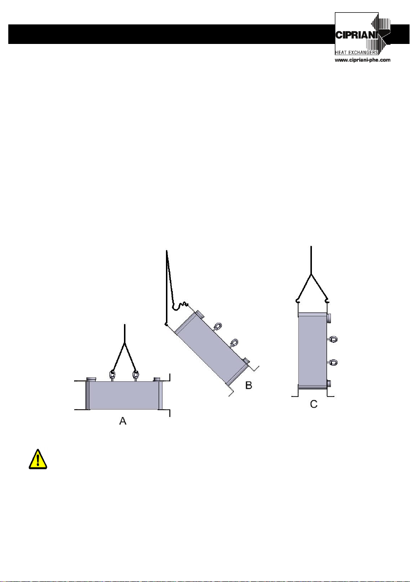
4. HANDLING AND TRANSPORTATION
LIFTING AND TRANSPORTATION MANEUVRES MUST BE
PERFORMED BY QUALIFIED PERSONNEL
5
EN
11,1+2,35*N (8,75+2,35*N)
0,965+0,062*N (0,881+0,062*N)
11,1+2,35*N (8,75+2,35*N)
1,293+0,089*N (1,182+0,089*N)
14,95+2,35*N (12,6+2,35*N)
1,811+0,128*N (1,661+0,128*N)
14,83+2,29*N (12.54+2,29*N)
2,338+0,13*N (2.168+0.13*N)
14,83+2,29*N (12,54+2,29*N)
3,024+0,186*N (2,798+0,186*N)
15,9+2,35*N (13,55+2,35*N)
8,505+0,389*N (6,983+0,389*N)
The plate exchanger includes attachments that protrude from the space occupied by the
equipment under pressure. It is therefore recommended to handle with maximum care to
prevent any impact or damage to the protruding parts.
Before handling the exchanger, it is necessary to verify the size and weight of the
exchanger, written to allow the choice of an adequate lifting system.
A steel or synthetic fibre lashing must be used, with payload exceeding the weight of the
load to be handled.
For exchangers of particular dimensions, please use the eyebolts specifically required for
the exchanger:
- A eyebolts in horizontal position
- B eyebolts in vertical position, lifting from horizontal to vertical position
- C eyebolts in vertical position, lifting from vertical position
CAUTION: DO NOT HANDLE THE EXCHANGER WHEN IT IS
UNDER PRESSURE
6
EN
11,1+2,35*N (8,75+2,35*N)
0,965+0,062*N (0,881+0,062*N)
11,1+2,35*N (8,75+2,35*N)
1,293+0,089*N (1,182+0,089*N)
14,95+2,35*N (12,6+2,35*N)
1,811+0,128*N (1,661+0,128*N)
14,83+2,29*N (12.54+2,29*N)
2,338+0,13*N (2.168+0.13*N)
14,83+2,29*N (12,54+2,29*N)
3,024+0,186*N (2,798+0,186*N)
15,9+2,35*N (13,55+2,35*N)
8,505+0,389*N (6,983+0,389*N)
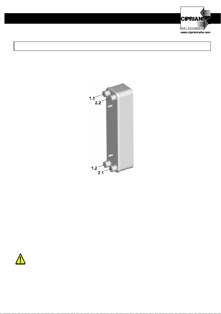
5. INSTALLATION
5.1 CONNECTIONS:
In standard versions the exchangers consist of 4 connections (1.1, 1.2 and 2.1, 2.2) in the
anterior part of the exchanger.
Connections are threaded internally (ISO-G).
Avoid excessive tightening of the connections. Excessive force may ruin the brazing where
the connection is placed.
5.2 FILTERS:
Install a filter higher than the exchanger to prevent particles and suspended solid materials
from entering the exchanger carried by the fluid. Clogging the canals may cause reduced
performance, an increase in load leaks and an increase in the risk of freezing. Select the
filter keeping in mind the minimum and maximum workload values of the exchanger.
Caution! Use a straining filter with passage holes not exceeding 900 micron.
7
EN
11,1+2,35*N (8,75+2,35*N)
0,965+0,062*N (0,881+0,062*N)
11,1+2,35*N (8,75+2,35*N)
1,293+0,089*N (1,182+0,089*N)
14,95+2,35*N (12,6+2,35*N)
1,811+0,128*N (1,661+0,128*N)
14,83+2,29*N (12.54+2,29*N)
2,338+0,13*N (2.168+0.13*N)
14,83+2,29*N (12,54+2,29*N)
3,024+0,186*N (2,798+0,186*N)
15,9+2,35*N (13,55+2,35*N)
8,505+0,389*N (6,983+0,389*N)
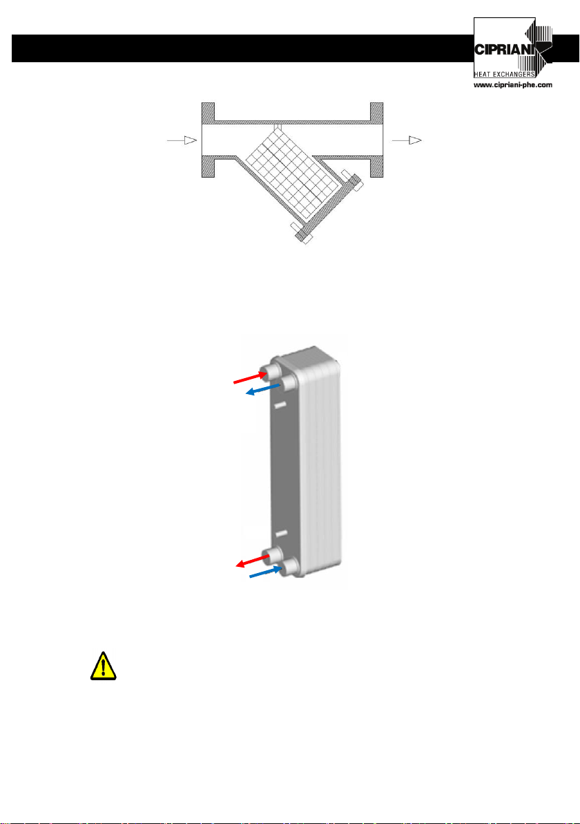
5.3 ASSEMBLY FOR WATER-WATER APPLICATION
For applications of the type water-water, in order to obtain optimal performance conditions,
connect so that the flow of fluids is against the current, as shown in the illustration:
For all uses:
•Avoid using quick-closure valves to prevent sudden flow interruptions and
water hammers
OUT
IN
2.2 –OUTLET
COLD FLUID
1.1 - INLET
HOT FLUID
1.2–OUTLET
HOT FLUID
2.1–INLET
COLD FLUID

8
EN
11,1+2,35*N (8,75+2,35*N)
0,965+0,062*N (0,881+0,062*N)
11,1+2,35*N (8,75+2,35*N)
1,293+0,089*N (1,182+0,089*N)
14,95+2,35*N (12,6+2,35*N)
1,811+0,128*N (1,661+0,128*N)
14,83+2,29*N (12.54+2,29*N)
2,338+0,13*N (2.168+0.13*N)
14,83+2,29*N (12,54+2,29*N)
3,024+0,186*N (2,798+0,186*N)
15,9+2,35*N (13,55+2,35*N)
8,505+0,389*N (6,983+0,389*N)
•To prevent fatigue breakage of the exchanger, avoid excessive temperature
and pressure fluctuations by using suitable adjustment systems.
•Verify compatibility between the fluids and the construction materials of the
exchanger.
5.5 Protection from vibration
Vibration coming from the system could damage the exchanger. Include flexible connections
or dilation compensators to prevent vibrations, pulsations and strain from transmitting to the
exchanger.
5.6 Isolation
Depending on the type of application, please isolate the exchanger.
6. USE
For correct functioning:
DO NOT EXCEED THE MAXIMUM APPLICABLE LLIMITS IN
TERMS OF PRESSURE (PS) AND (TS) SHOWN ON THE DATA TAG
Use anti-freezing solutions in the case in which the temperatue is close
to the freezing point of the liquid, after verifying its compatibility with the
construction materials of the exchanger.
7. MAINTENANCE AND USER CHECKS
DO NOT OPEN THE EXCHANGER WHEN IT IS UNDER PRESSURE.
9
EN
11,1+2,35*N (8,75+2,35*N)
0,965+0,062*N (0,881+0,062*N)
11,1+2,35*N (8,75+2,35*N)
1,293+0,089*N (1,182+0,089*N)
14,95+2,35*N (12,6+2,35*N)
1,811+0,128*N (1,661+0,128*N)
14,83+2,29*N (12.54+2,29*N)
2,338+0,13*N (2.168+0.13*N)
14,83+2,29*N (12,54+2,29*N)
3,024+0,186*N (2,798+0,186*N)
15,9+2,35*N (13,55+2,35*N)
8,505+0,389*N (6,983+0,389*N)
WATER CIRCUIT CLEANING:
In case of particularly hard water with a tendency to form deposits, it is possible to clean the
exchanger through CIP (Cleaning In Place). There may be a decrease in performance due
to the presence of deposits inside the exchanger. In such cases, force-wash using a
suitable descaling chemical solution, after checking the compatibility with the construction
materials of the exchanger.
Chemical washing must be carried out inside the water circuit; pump the chemical solution
in the opposite direction to the one in the normal operation of the circuit.
For optimal cleaning, the flow of the descaling product should be at least 1.5 times greater
than the normal flow used.
Do not clean circuits working with cooling gas.
Cleaning must be performed by specialised personnel.
Always rinse the circuits with fresh water after chemical washing.
8. SAFETY
•Always install safety accessories compliant to the national regulations of the country of
use; a fire for external causes will provoke the exceeding of admissible limits for
pressurised equipment.
•Do not expose pressurised equipment to any impact during functioning.
•Do not weld on the equipment body under pressure.
•Do not use the pressurised equipment for uses that differ from what is prescribed.
•In case of leak detection, immediately switch off the functioning exchanger.

10
EN
11,1+2,35*N (8,75+2,35*N)
0,965+0,062*N (0,881+0,062*N)
11,1+2,35*N (8,75+2,35*N)
1,293+0,089*N (1,182+0,089*N)
14,95+2,35*N (12,6+2,35*N)
1,811+0,128*N (1,661+0,128*N)
14,83+2,29*N (12.54+2,29*N)
2,338+0,13*N (2.168+0.13*N)
14,83+2,29*N (12,54+2,29*N)
3,024+0,186*N (2,798+0,186*N)
15,9+2,35*N (13,55+2,35*N)
8,505+0,389*N (6,983+0,389*N)
9. DISPOSAL
This pressurised equipment contains recyclable materials: when the machinery stops
functioning, please enquire on the current regulations in your country on the matter of
recycling.

11
EN
11,1+2,35*N (8,75+2,35*N)
0,965+0,062*N (0,881+0,062*N)
11,1+2,35*N (8,75+2,35*N)
1,293+0,089*N (1,182+0,089*N)
14,95+2,35*N (12,6+2,35*N)
1,811+0,128*N (1,661+0,128*N)
14,83+2,29*N (12.54+2,29*N)
2,338+0,13*N (2.168+0.13*N)
14,83+2,29*N (12,54+2,29*N)
3,024+0,186*N (2,798+0,186*N)
15,9+2,35*N (13,55+2,35*N)
8,505+0,389*N (6,983+0,389*N)
ITALIANO
SOMMARIO
ITALIANO.............................................................................................................................11
MASSIMA CATEGORIA APPLICABILE PER MODELLO ...................................................12
1. AVVERTENZE PRELIMINARI..........................................................................................13
2. INTRODUZIONE ..............................................................................................................13
3. RICEVIMENTO DEL MATERIALE ...................................................................................13
4. MOVIMENTAZIONE ETRASPORTO...............................................................................13
5. INSTALLAZIONE.............................................................................................................15
6. IMPIEGO ..........................................................................................................................17
7. MANUTENZIONE ECONTROLLI DA PARTE DELL’UTILIZZATORE.............................18
8. SICUREZZA.....................................................................................................................18
9. SMALTIMENTO ...............................................................................................................19

12
EN
11,1+2,35*N (8,75+2,35*N)
0,965+0,062*N (0,881+0,062*N)
11,1+2,35*N (8,75+2,35*N)
1,293+0,089*N (1,182+0,089*N)
14,95+2,35*N (12,6+2,35*N)
1,811+0,128*N (1,661+0,128*N)
14,83+2,29*N (12.54+2,29*N)
2,338+0,13*N (2.168+0.13*N)
14,83+2,29*N (12,54+2,29*N)
3,024+0,186*N (2,798+0,186*N)
15,9+2,35*N (13,55+2,35*N)
8,505+0,389*N (6,983+0,389*N)
MASSIMA CATEGORIA APPLICABILE PER MODELLO
Gli scambiatori a piastre CIPRIANI PHE SRL possono essere utilizzati come scambiatori di
calore monofase (gas/gas).
Per ciascuna tipologia di scambiatori viene riportata nelle tabelle successive in accordo alla
PED 2014/68/EU, la categoria di appartenenza calcolata alla pressione massima
ammissibile relativa a ciascun modello.
SSA 07 SSA 09 SSA 62 SSA 82 SSA X2
PS=16bar PS=16bar PS=16bar PS=16bar PS=16bar
Fluid Gr.2 - G Fluid Gr.2 - G Fluid Gr.2 - G Fluid Gr.2 - G Fluid Gr.2 - G
Art. 4.3 0-120 0-120 0-80 0-50 0-22
Cat.I 82-120 52-150 24-92
Cat.II 94-240
Cat.III
Cat.IV
Gli scambiatori sono idonei per fluidi che appartengono al Gruppo 2.
Per altri fluidi contattare CIPRIANI PHE SRL.

13
EN
11,1+2,35*N (8,75+2,35*N)
0,965+0,062*N (0,881+0,062*N)
11,1+2,35*N (8,75+2,35*N)
1,293+0,089*N (1,182+0,089*N)
14,95+2,35*N (12,6+2,35*N)
1,811+0,128*N (1,661+0,128*N)
14,83+2,29*N (12.54+2,29*N)
2,338+0,13*N (2.168+0.13*N)
14,83+2,29*N (12,54+2,29*N)
3,024+0,186*N (2,798+0,186*N)
15,9+2,35*N (13,55+2,35*N)
8,505+0,389*N (6,983+0,389*N)
1. AVVERTENZE PRELIMINARI
Le presenti Istruzioni Operative devono essere custodite in buono stato di conservazione ed
in luogo facilmente accessibile al personale addetto.
•Le presenti Istruzioni Operative non esonerano dal rispetto delle legislazioni vigenti
sulle norme di sicurezza ed antinfortunistica.
•CIPRIANI PHE SRL DECLINA OGNI RESPONSABILITA’ in caso di:
uso improprio dell’attrezzatura in pressione;
modifiche all’attrezzatura in pressione;
inadempimento alle vigenti norme di sicurezza ed antinfortunistiche;
non osservanza di quanto contenuto nelle presenti Istruzioni Operative.
2. INTRODUZIONE
Gli scambiatori a piastre sono costituiti da un pacco di piastre corrugate impilate l’una
sull’altra tra 2 piastre di chiusura. Il pacco di piastre viene sottoposto ad un processo di
brasatura con la formazione di 2 circuiti separati.
3. RICEVIMENTO DEL MATERIALE
Prima di effettuare qualsiasi operazione sullo scambiatore, controllare la corrispondenza tra
apparecchio consegnato e quello ordinato.
Verificare, inoltre, che il modello dello scambiatore sia stato adeguatamente dimensionato
con il programma di selezione CIPRIANI PHE SRL per il tipo di applicazione.
3.1 Documentazione allegata
Unitamente allo scambiatore vengono sempre fornite le presenti Istruzioni Operative.
4. MOVIMENTAZIONE E TRASPORTO
LE MANOVRE DI SOLLEVAMENTO E TRASPORTO DEVONO
ESSERE ESEGUITE SOLAMENTE DA PERSONALE QUALIFICATO

14
EN
11,1+2,35*N (8,75+2,35*N)
0,965+0,062*N (0,881+0,062*N)
11,1+2,35*N (8,75+2,35*N)
1,293+0,089*N (1,182+0,089*N)
14,95+2,35*N (12,6+2,35*N)
1,811+0,128*N (1,661+0,128*N)
14,83+2,29*N (12.54+2,29*N)
2,338+0,13*N (2.168+0.13*N)
14,83+2,29*N (12,54+2,29*N)
3,024+0,186*N (2,798+0,186*N)
15,9+2,35*N (13,55+2,35*N)
8,505+0,389*N (6,983+0,389*N)
Lo scambiatore a piastre presenta degli attacchi che sono sporgenti dall’ingombro
dell’attrezzatura in pressione. Si raccomanda, quindi, la massima attenzione nella
movimentazione per non provocare urti o danni alle parti sporgenti.
Prima di movimentare lo scambiatore è necessario verificare le dimensioni e il peso dello
scambiatore, riportati per poter scegliere un adeguato sistema di sollevamento.
Deve essere utilizzata un’imbracatura di acciaio, di catena o di fibra sintetica, di portata
superiore al carico da movimentare
Per gli scambiatori di certe dimensioni utilizzare i golfari appositamente previsti nello
scambiatore:
- A golfari in posizione orizzontale
- B golfari in posizione verticale, sollevamento dalla posizione orizzontale a quella
verticale
- C golfari in posizione verticale, sollevamento dalla posizione verticale
ATTENZIONE NON MOVIMENTARE LO SCAMBIATORE QUANDO
È POSTO IN PRESSIONE
15
EN
11,1+2,35*N (8,75+2,35*N)
0,965+0,062*N (0,881+0,062*N)
11,1+2,35*N (8,75+2,35*N)
1,293+0,089*N (1,182+0,089*N)
14,95+2,35*N (12,6+2,35*N)
1,811+0,128*N (1,661+0,128*N)
14,83+2,29*N (12.54+2,29*N)
2,338+0,13*N (2.168+0.13*N)
14,83+2,29*N (12,54+2,29*N)
3,024+0,186*N (2,798+0,186*N)
15,9+2,35*N (13,55+2,35*N)
8,505+0,389*N (6,983+0,389*N)
5. INSTALLAZIONE
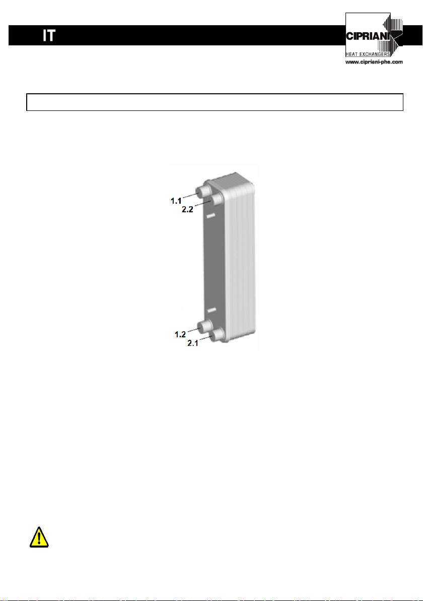
5.1 Connessioni:
Nelle versioni standard gli scambiatori a piastre presentano 4 connessioni (1.1, 1.2 e 2.1,
2.2) nella parte anteriore dello scambiatore.
(NB: corrispondenza connessioni con disegno di approvazione 1.1=A2/B2 , 1.2=A1/B1 , 2.2=A3-B3 , 2.1=A4-B4)
Le connessioni sono del tipo: filettato interno (ISO-G).
Evitare l’eccessivo serraggio delle connessioni. Una forza eccessiva può rovinare la
brasatura in corrispondenza della connessione.
5.2 Filtri:
Installare un filtro a monte dello scambiatore per evitare l’ingresso all’interno dello
scambiatore di particelle e solidi sospesi trascinati dal fluido. Un intasamento dei canali può
causare diminuzioni di prestazione, un aumento delle perdite di carico e aumentare il rischio
di congelamento.
Selezionare il filtro tenendo conto dei valori di portata minima e massima di lavoro dello
scambiatore.
Attenzione! Utilizzare un filtro a maglia con fori di passaggio non superiori 900 micron.
16
EN
11,1+2,35*N (8,75+2,35*N)
0,965+0,062*N (0,881+0,062*N)
11,1+2,35*N (8,75+2,35*N)
1,293+0,089*N (1,182+0,089*N)
14,95+2,35*N (12,6+2,35*N)
1,811+0,128*N (1,661+0,128*N)
14,83+2,29*N (12.54+2,29*N)
2,338+0,13*N (2.168+0.13*N)
14,83+2,29*N (12,54+2,29*N)
3,024+0,186*N (2,798+0,186*N)
15,9+2,35*N (13,55+2,35*N)
8,505+0,389*N (6,983+0,389*N)
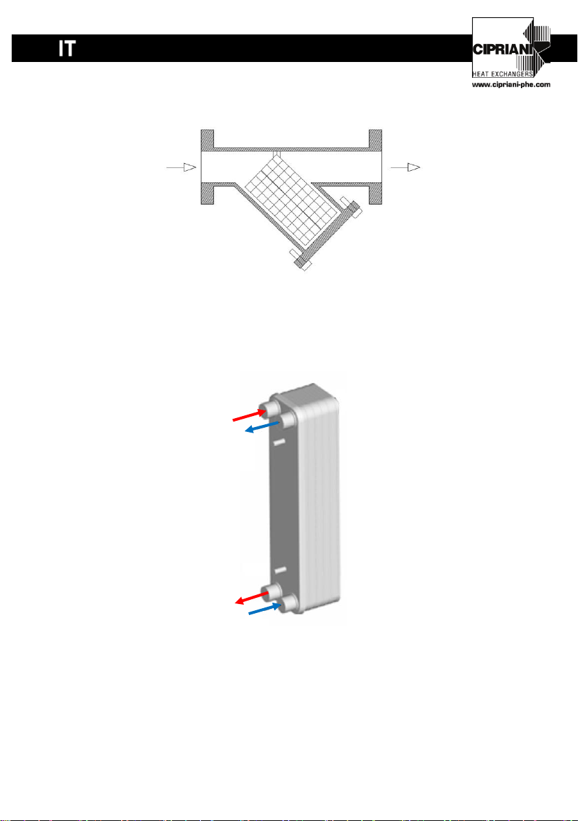
5.3 MONTAGGIO PER APPLICAZIONE ACQUA-ACQUA
In applicazioni di tipo acqua-acqua per ottenere condizioni di prestazione ottimali eseguire il
collegamento in modo che il flusso dei fluidi sia controcorrente come in figura:
(NB: corrispondenza connessioni con disegno di approvazione 1.1=A2/B2 , 1.2=A1/B1 , 2.2=A3-B3 , 2.1=A4-B4)
2.2 - USCITA
FLUIDO FREDDO
1.1 - INGRESSO
FLUIDO CALDO
1.2- USCITA
FLUIDO CALDO
2.1–INGRESSO
FLUIDO FREDDO
17
EN
11,1+2,35*N (8,75+2,35*N)
0,965+0,062*N (0,881+0,062*N)
11,1+2,35*N (8,75+2,35*N)
1,293+0,089*N (1,182+0,089*N)
14,95+2,35*N (12,6+2,35*N)
1,811+0,128*N (1,661+0,128*N)
14,83+2,29*N (12.54+2,29*N)
2,338+0,13*N (2.168+0.13*N)
14,83+2,29*N (12,54+2,29*N)
3,024+0,186*N (2,798+0,186*N)
15,9+2,35*N (13,55+2,35*N)
8,505+0,389*N (6,983+0,389*N)
Per tutti gli utilizzi:
•Evitare l’utilizzo di valvole a chiusura rapide per non avere brusche
interruzioni di flusso ed evitare quindi colpi d’ariete.
•Per evitare la rottura a fatica dello scambiatore evitare eccessive fluttuazioni
di temperatura e pressioni tramite opportuni sistemi di regolazione
•Verificare la compatibilità tra i fluidi e i materiali di costruzione dello
scambiatore
5.5 Protezione dalle vibrazioni
Le vibrazioni provenienti dal sistema possono provocare danneggiamenti allo scambiatore.
Prevedere quindi collegamenti flessibili o compensatori di dilatazione per evitare che
vibrazioni pulsazioni e sollecitazioni vengano trasmessi allo scambiatore.
5.6 Isolamento
In base al tipo di applicazione prevedere l’isolamento dello scambiatore.
6. IMPIEGO
Per un corretto funzionamento:
NON SUPERARE I LIMITI MASSIMI AMMISSIBILI IN TERMINI
DI PRESSIONE (PS) E TEMPERATURA (TS) INDICATI SULLA
TARGHETTA DATI
Utilizzare delle soluzioni anticongelanti nel caso in cui la temperatura sia
prossima alla temperatura di congelamento del fluido, dopo averne verificato
la compatibilità con il materiale di costruzione dello scambiatore
18
EN
11,1+2,35*N (8,75+2,35*N)
0,965+0,062*N (0,881+0,062*N)
11,1+2,35*N (8,75+2,35*N)
1,293+0,089*N (1,182+0,089*N)
14,95+2,35*N (12,6+2,35*N)
1,811+0,128*N (1,661+0,128*N)
14,83+2,29*N (12.54+2,29*N)
2,338+0,13*N (2.168+0.13*N)
14,83+2,29*N (12,54+2,29*N)
3,024+0,186*N (2,798+0,186*N)
15,9+2,35*N (13,55+2,35*N)
8,505+0,389*N (6,983+0,389*N)
7. MANUTENZIONE E CONTROLLI DA PARTE
DELL’UTILIZZATORE
NON APRIRE LO SCAMBIATORE QUANDO E’ POSTO IN PRESSIONE.
PULIZIA CIRCUITO ACQUA :
In caso di utilizzo di acqua particolarmente dura con tendenza a formare incrostazioni è
possibile eseguire la pulizia dello scambiatore tramite CIP (Cleaning In Place). In seguito
alla presenza di incrostazioni all’interno dello scambiatore può essere riscontrata una
diminuzione di prestazione. In tali casi eseguire un lavaggio forzato utilizzando un'adeguata
soluzione chimica disincrostante dopo averne verificato la compatibilità con i materiali di
costruzione dello scambiatore.
Il lavaggio chimico deve essere eseguito nel circuito acqua, pompare la soluzione chimica
nella direzione opposta a quella normale di funzionamento del circuito.
Per una pulizia ottimale, il flusso del prodotto disincrostante dovrebbe essere almeno 1.5
volte maggiore del flusso normale impiegato.
Il lavaggio deve essere eseguito da personale specializzato
Sciacquare sempre con acqua fresca i circuiti dopo il lavaggio chimico.
8. SICUREZZA
•Installare sempre accessori di sicurezza conformi alla normativa nazionale del paese
di utilizzo; un incendio per cause esterne provoca il superamento dei limiti ammissibili per
l’attrezzatura in pressione.
•Non sottoporre l’attrezzatura in pressione a qualsiasi urto durante il funzionamento.
•Non eseguire saldature sul corpo dell’attrezzatura in pressione.
•Non utilizzare l’attrezzatura in pressione per usi diversi da quanto prescritto.

19
EN
11,1+2,35*N (8,75+2,35*N)
0,965+0,062*N (0,881+0,062*N)
11,1+2,35*N (8,75+2,35*N)
1,293+0,089*N (1,182+0,089*N)
14,95+2,35*N (12,6+2,35*N)
1,811+0,128*N (1,661+0,128*N)
14,83+2,29*N (12.54+2,29*N)
2,338+0,13*N (2.168+0.13*N)
14,83+2,29*N (12,54+2,29*N)
3,024+0,186*N (2,798+0,186*N)
15,9+2,35*N (13,55+2,35*N)
8,505+0,389*N (6,983+0,389*N)
•In caso di rilevamento di perdita, arrestare immediatamente il funzionamento dello
scambiatore.
9. SMALTIMENTO
Questa attrezzatura in pressione contiene materiale riciclabile; al termine della vita utile
dell’apparecchio informatevi sulle norme vigenti nel vostro paese in materia di riciclaggio.

20
EN
11,1+2,35*N (8,75+2,35*N)
0,965+0,062*N (0,881+0,062*N)
11,1+2,35*N (8,75+2,35*N)
1,293+0,089*N (1,182+0,089*N)
14,95+2,35*N (12,6+2,35*N)
1,811+0,128*N (1,661+0,128*N)
14,83+2,29*N (12.54+2,29*N)
2,338+0,13*N (2.168+0.13*N)
14,83+2,29*N (12,54+2,29*N)
3,024+0,186*N (2,798+0,186*N)
15,9+2,35*N (13,55+2,35*N)
8,505+0,389*N (6,983+0,389*N)
Il vostro contatto / Your Contact:
CIPRIANI PHE SRL
Via Nassar, 46
37026 PESCANTINA (VR) - ITALY
Telefono +39 045 6750065
info@cipriani-phe.com
Costruttore: ONDA S.p.A., Via Vittoria, 158 36065 Mussolente (VI) - ITALY
This manual suits for next models
4
Table of contents
Languages:
Other CIPRIANI Industrial Equipment manuals


