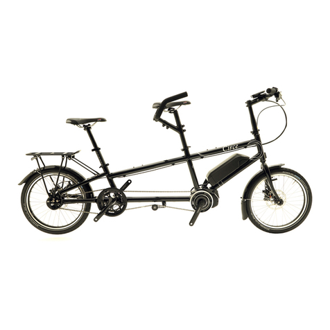
Circe Cycles Morpheus User manual

Assembly Manual
Morpheus
V1.00

Contents
INTRODUCTION.......................................................................................................................................3
UNPACKING............................................................................................................................................3
CONTENTS OF MAIN BOX ............................................................................................................3
CONTENTS OF SMALL PARTS BOX ...............................................................................................3
ASSEMBLY................................................................................................................................................3
TOOLS REQUIRED .........................................................................................................................3
POSITIONING THE CAPTAIN’S HANDLEBARS ..............................................................................4
INSTALLING STOKER SEAT.............................................................................................................4
INSTALLING STOKER HANDLEBARS ..............................................................................................4
INSTALLING THE BOOM ...............................................................................................................5
ADJUSTING THE TIMING CHAIN...................................................................................................5
INSTALLING THE FRONT STAND ...................................................................................................5
INSTALLING THE KIDDY SYSTEM....................................................................................................5
INSTALLING THE PEDALS...............................................................................................................6
BELL AND REFLECTORS.................................................................................................................6
PRE-RIDE........................................................................................................................................6
FIRST RIDE .....................................................................................................................................6
APPENDIX A ............................................................................................................................................7

3
Circe Cycles
CONTENTS OF SMALL PARTS BOX
The small parts box should contain the following,
however there may be additional parts in the box
depending on what has been ordered:
• Seat including support stays
• Boomwithcranktted
• Manuals,reectorsandbell
• Stoker handlebars
• Main section of Front stand*
• Pedals*
• Charger, power cable, battery, and adaptor
(Pendix only)*
* Optional extras
ASSEMBLY
Find plenty of space to lay out the parts and gather
the tools you will need.
NOTE - Only cut clear zip ties when unpacking.
TOOLS REQUIRED
• 4,5 and 6mm Allen key
• Torque wrench (Optional)
• Cable cutters or robust scissors for cutting zip
ties
INTRODUCTION
This manual is intended for those who have bought
their Morpheus directly from Circe Cycles and
have received their tandem packed in a box.
This manual is to help you unpack and assemble
your tandem. After this you can refer to the
Owner’s manual to help with adjustment and more
comprehensive setup.
To further help with assembling your tandem, there
are instructional videos available on the manuals
page of our website.
www.circecycles.com/products/morpheus/
manuals/
UNPACKING
Make sure that both boxes are the correct way up
before opening. Remove all the loose packaging
and any loose parts from around the bike. Remove
the tandem from the box, a second set of hands
makes this easier.
The seat, small components and accessories
comes in a separate box to the main part of the
tandem, please follow the same procedure as
above for unpacking.
NOTE - Check that everything is present and
undamaged before proceeding to assembly.
CONTENTS OF MAIN BOX
The main box should contain:
• The tandem with the captain’s handlebars
folded down and to one side of the frame
• Racks*andrearstand*shouldbettedtothe
bike.
• Front stand* will have the main section
removed with just the struts attahced to the
frame.
• Front and rear mudguards*
• Kiddy system main body* (if ordered)
* Optional extras

4
Circe Cycles
NOTE – The P clip holding the cables should be on
the inside of the clamps and on the left hand side
of the bike.
Thelowerseatmounttstotheframeviaabolt
and lever. There are three potential positions for
the bolt to be in, depending on the desired position
of the seat. The bolt is tightened by rotating the
black lever clockwise, whilst holding the nut on the
other side. The lever can’t rotate fully because of
the seat, so it is possible to disengage the lever by
pressing the red button and pulling the lever out,
allowing it to be rotated freely back to a suitable
starting position.
INSTALLING STOKER HANDLEBARS
The stoker bars slide into the tube to the rear of the
lowerseatmountingpoint,andarexedinplace
using the quick release clamps. The bars should be
positioned so the foam grip is facing forward and
slightly tilted up.
NOTE - f you have a Front stand the stoker bar is
used to hold the upper clamp.
• 10mm spanner (Front stand, Kiddy system)
• 15mm pedal spanner
POSITIONING THE CAPTAIN’S HANDLEBARS
Remove any zip ties that are holding the handlebar
and loosen the four stem bolts using an Allen key.
The bars can now be turned to an upright postition,
a good starting point is shown below, but can easily
be adjusted to suit your riding style. The stem should
facing towards the back of the bike and needs to
alignedwiththefrontwheel,thenxedinplaceby
tightening the two pinch bolts on the stem.
The handlebar extensions are adjusted using a
quick release and should be fully tightened before
riding. Once the handlebar and front wheel are
aligned the stem bolts should be tightened to the
recommended torques settings in the torque table
Appendix A.
NOTE – It’s easier to align the handlebar and front
wheel with the stoker seat removed.
INSTALLING STOKER SEAT
The stoker seat mounts to the frame at two
locations. The upper mount has two tubes which
slide into the corresponding clamps on the frame.

5
Circe Cycles
INSTALLING THE BOOM
First, remove any packaging from around the
end of the main tube on the bike, including the
transportation bung, which is inserted into the
end of the boom to prevent damage. The boom
can then be slid into the main tube and the
chain looped over the chainring. The boom can
be set to the length required and the two pinch
bolts tightened to the recommended torque, see
Appendix A
NOTE – Tighten the pinch bolts evenly to prevent
damage to the frame
ADJUSTING THE TIMING CHAIN
The timing chain can be tensioned by undoing the
quick release on the tensioner arm and rotating
the arm to take up the slack in the chain. If the
tensioner alone can’t take up the slack in the
chain, it is possible to shorten the timing chain by
removing some chain links.
INSTALLING THE FRONT STAND
(Optional extra) The bike is packed with the lower
standbracettedtothedowntube,themain
section of the stand is packed separately in the
small parts box. The stand mounts to the frame at
two points; the upper clamp, slides over the stoker
bars, as shown earlier in the manual. The lower
mount is via the brace, the arms of the brace need
to be bolted to the main body of the stand using
the supplied nut and bolts.
INSTALLING THE KIDDY SYSTEM
(Optional extra) The Kiddy system main body
should be mouted to the main tube of the tandem,
the crank assembly will be pocked separately in
the small parts box.
To mount the crank assembly to the main body, the
T nuts need to be aligned with the corresponding
slots in the main body.
NOTE – It’s easier to mount the T nuts to the channel
if one T nut has the long end facing out with the
opposite side T nut facing in.

6
Circe Cycles
Once the crank assmbly is positioned on the main
tubeitcanbexedinplaceusingthefourM6hex
bolts and a 10mm spanner.
INSTALLING THE PEDALS
(Your own if not ordered from us) – The pedal
threads are handed. The right hand pedal tightens
in the normal direction; the left-hand pedal has
a left-hand thread, and tightens in the opposite
direction to normal. Tighten the pedals to the
torque shown in Appendix A.
BELL AND REFLECTORS
Reectorsandabellaresuppliedwithyour
tandem. The bell can be mounted anywhere on
the handlebars where it can be reached easily.
Thefrontreectorcanalsobemountedtothetab
ontheendoftheboom.Therearreectortsto
theCaptain’sseatpost,ensurethatthereectoris
visible at the height you intend to have the post at.
Ifnot,youmayneedtorepositionthereectorso
that it is visible.
PRE-RIDE
Check all nuts, bolts and quick releases to make
sure everything is tight (See appendix A for torque
settings). Ensure the wheels spin freely and the
brakes function correctly.
FIRST RIDE
Check the gears shift correctly, refer to the Owner’s
manual, or manufacturers manual, for adjustment.
Payattentiontothetandmakeanyadjustments
required, once you are stationary. Finally, ensure
there are no rattles or unexpected sounds.
YoucannowrefertotheUser’smanualfornalset
up and on-going maintenance.

7
Circe Cycles
Fastener Allen key size (mm) Nm In-lbf Loctite
Extender clamp top bolt 5 8 71
Extender clamp bolt 5 8 71
Stem bolts 4 6 53
Alnehubnut 15 spanner 30-45 265-398
V brake mounting bolt 5 6-8 53-71 Y
Front derailleur clamp bolt 5 3-5 27-44
Front derailleur cable clamp bolt 5 5-7 44-62
Pedals (Allen key) 8 35 310
Pedals (spanner) 15 spanner 35 310
Thru axle M15 x 1.5 6 17 150
Brake lever clamp bolt 4-5 6-8 53-71
Adjustable drop out M8 bolt 6 15-17 130 -150
Mechanical caliper mounting bolt 5 9-10 80-89 Y
Rohloff disc rotor bolt 5 7 62 Y
Rohloff M4x25 retaining plate T-20 3 27
Rear derailleur mounting bolt 5 10 89
Rear derailleur cable clamp bolt 5 4-5 38-44
Disc rotor bolt T-25 2-4 18-35 Y
Separable coupling bolt 6 15-19 130-168
Separable drainpipe bolt 6 15-19 130-168
Shimano hollowtech crank bolt 5 10-14 88-132
Square taper crank bolt 8 34-44 305-391
ShimanoC/Ldisctting HG tool 40-50 350-435
All other M4 bolts 3 5-6 44-53
All other M5 bolts 4 6-8 53-71
All other M6 bolts 5 8-10 70-89
Tightening Torques Table
APPENDIX A

Allphotos,illustrations,colours,weights,andspecicationscontainedinthiscataloguearebasedonthelatest
production information at the time of publication. Circe Cycles reserves the right to make changes at any time, without
notice,incolours,materials,equipment,specications,andmodels.Somemodelsmaybeshownwithoptional
equipment.Pleasecheckmodelavailabilityandfullspecicationwithyourdealerpriortoordering.
www.circecycles.com
Other manuals for Morpheus
1
Table of contents
Other Circe Cycles Bicycle manuals
Popular Bicycle manuals by other brands

Electra
Electra Townie GO! owner's manual

Yeti Cycles
Yeti Cycles 2010 AS-R 7 owner's manual
Batribike
Batribike MERCURY user manual
Hercules
Hercules FAZUA Futuro 10 FA 20" 252Wh 10G S Translation of the original operating instructions

Hudora
Hudora Bikey INSTRUCTIONS ON ASSEMBLY AND USE
PED Bicycles
PED Bicycles Birdy owner's manual

