Zoomo Sport User manual

Zoomo Sport
User Manual

INTRODUCTION
Zoomo e-bikes are rigorously engineered for maximum performance, safety, reliability and
utility. This user manual outlines how to operate the dierent aspects of your Zoomo e-bike
and shows how you can keep your Zoomo e-bike in optimal condition.
Please make sure to have read and understood the complete user manual before using your
Zoomo e-bike, as it contains a lot of information relevant to your personal safety.
Non-observance may lead to serious accidents, as well as personal or material damage.
Each person using, repairing, servicing or disposing of your Zoomo e-bike, has to fully
acknowledge and understand the content of the user manual. If there still are any unanswered
questions please contact your local Zoomo workshop or dealer.
This user manual is part of the scope of delivery of your Zoomo e-bike. It is only valid for the
product shipped along with it. Please make sure to store this manual in a safe place. Please
also make sure you understand your national guidelines before using your Zoomo e-bike on
public roads. The contents of this manual could be altered without prior
public announcement.
Updates can be found on our website:
Head Oce
Zoomo
Unit 41, 112 McEvoy Street,
Alexandria, 2015 NSW, Australia
www.ridezoomo.com

GENERAL WARNINGS
! Turn the assistance o when you step o the bicycle. Never walk with enabled assistance.
!Keep the left brake lever (brakes are supplied with brake circuit-breaker) pressed in when you
are stationary with enabled power assistance.
!Always wear suitable clothing and make yourself visible to drivers.
!Check your local helmet standards and consider always wearing a helmet when using the bike.
!Don’t use a high-pressure hose to clean the bicycle. A powerful beam of water can damage
the electronics of the bike. The warranty will be void.
!If you detect a problem with the bike, book a repair / service before using the bike again.
!Take the time to get used to your new bike. The powerful disk brakes do not need a strong
pull on the lever to slow you down.
! An electric bike behaves slightly dierently to a normal bike, notably faster acceleration.
A progressive riding approach will help you get used to it.
01

CONTENTS
1. Warnings 01
2. Vehicle Overview 04
3. Riding Position and Setup 06
a. Saddle Height 06
b. Saddle Position 07
c. Setting Saddle Angle - One Bolt 07
d. Setting Saddle Angle - Two Bolts 07
e. Brake Lever Position 07
f. Headset 07
4. Pedals 08
5. Wheel Axles 09
a. Front Quick Release Axle 09
b. Opening The Quick Release Axle 09
c. Reliable Tightening 09
6. Derailleur 10
7. Suspension 11
a. Fork Lockout System 11
b. Pre-stress of the Fork Setting 12
8. Brake Adjustment 14
9. Starting / Shutdown of System 16
a. Switch on battery 16
b. Activate display 16
c. Scan RFID 16
d. USB charging 16
e. Pedal assist modes 16
9. Shutting Down the Bike 17
a. With motor lock 17
b. Without motor lock 17
10. Zoomo Batteries (Warnings) 18
a. Removing the battery 18
b. Charging the battery 18
11. Mudguards and Luggage Rack 19
a. Mudguard clearance 19
b. Luggage rack & payload 19
c. Use of trailer 20
12. Maintenance 20
a. Before and after each ride 20
b. Every month 20
13. Controller Error Codes 21
a. Controller 21
b. Battery 21
14. Certications 22
15. Tampering Disclaimer 22
16. Emissions 22
17. Environmental Protection 22
02

OVERVIEW DIAGRAM
1. Display
2. Brake Lever
3. Stem
4. Headset
5. Front Light
6. Front Fender
7. Fork
8. Rim
9. Brake Calliper Front
10. Rotor
11. Spokes
12. Tyre
13. Downtube
14. Battery
15. Drink Bottle Holder
16. Saddle
17. Seatpost
18. Carrier
19. Rear Light
20. Rear Fender
21. Rear Brake Caliper
22. Rear Motor
23. Rear Axle
24. Chain Ring
25. Crank
26. Pedal
27. Stand
1
14
15
16
17
18
19
20
21
22
23
24
25
26
27
2
3
4
5
6
7
8
9
10
11
12
13
03

RECOMMENDED TORQUE RATINGS (TABLE 1)
TRANSMISSION
Rear derailleur
Gear lever
Cassette
Crank
Pedal
Chain guide
Rear wheel
Hanger Bolt
Cable screw
Derailleur guard
Fixation screw
Lock ring
Fixation screw on crank axle
Pedal axle
Fixation screw
Nut
8 - 10 Nm
5 - 7 Nm
3 - 4 Nm
5 Nm
40 Nm
45 - 50 Nm
15 Nm
5 Nm
30 Nm
COCKPIT
Saddle on seat post
Stem
Grips
Seat post with 1 tting block
Seat post with 2 tting block
Seat post clamp
Screw on the handle bar
Screw on the pivot
Screw on the stem cover
Fixation screw
22 Nm
12 Nm
5 Nm
5 Nm
6 - 8 Nm
3 Nm
2 - 3 Nm
ACCESSORIES
Mudguard
Kick-stand
Fixation screw on the fork
Fixation screw on the support
Fixation screw on luggage
rack / frame
Fixation screw
5 Nm
3 Nm
5 Nm
6 - 8 Nm
BRAKES
Brake caliper
Brake lever on handlebar
Disc brake
Fixation screw on the
frame / fork
Fixation screw on the
brake lever
Fixation screw on the hub
Shimano center lock bolt
5 Nm
4 Nm
4 Nm
40 Nm
Component Screws and bolts Torque Value
04

To adjust the height, you need to open
the seat clamp’s quick release or unscrew
the screw on the seat clamp with a 4 or
5 mm allen key.
Once the height is adjusted, close the
quick release lever. If necessary, adjust
the tightness level on the opposite nut so
that the lever tightens around midway
through closing.
In the case of a seat clamp with screw,
tighten the screw to the recommended
torque level which is 5 - 6 Nm.
Never go past the recommended
torque level.
A. SADDLE HEIGHT
The rst set up to carry out on your Zoomo
is the saddle height. Once again, your local
workshop can help you do this.
You must not hesitate to adjust this if you
do not nd the correct height immediately.
We have a good tip to help you nd the
correct setting quickly: position the crank
in line with the seat tube, without being
lopsided on the saddle and place your heel
on the pedal with your leg almost straight.
(see Figure 2)
Never go over the maximum height level
on your seat post marked by the
engraving « INSERT MIN » or « STOP ».
This is for your safety, as well as the
reliability of your bike.
Figure 2. Ideal Post Height.
Figure 3. Minimum insert level seatpost.
RIDING POSITION & BIKE SETUP
05

B. SETTING SADDLE POSITION
We have equipped our bikes with
ergonomic saddles, but a careful set up is
required to ensure optimal comfort. In
this section you will nd advice for an
angle and set back of your saddle, that’s
adjusted to the type of riding you do. It is
generally advised to position the saddle
horizontally for a mixed usage.
The saddle set back (position on the
horizontal slides) should be adjusted for
the length of the femur. In general an
intermediate setback is adequate as
shown in Figure 4 above.
C. SETTING SADDLE ANGLE -
ONE BOLT
This applies if you nd a single bolt
underneath your saddle. To adjust the
angle of your saddle you need to carry
out the following process:
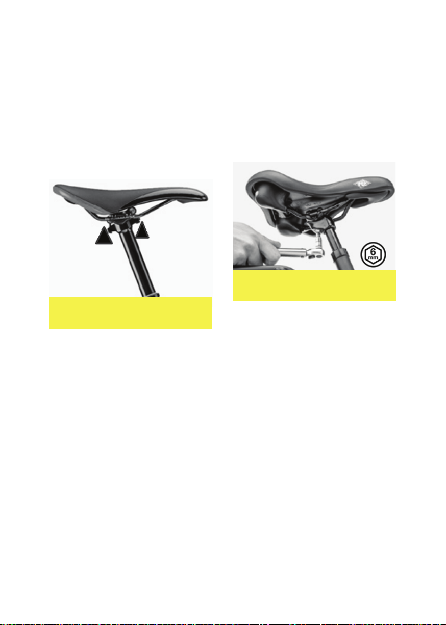
1. Loosen the screw that holds the
saddle and seat post using a 6 mm
allen key to obtain enough play to
easily move the saddle.
(see Figure 8)
Figure 4. Intermediate saddle
setback position.
2. Adjust the angle and setback of the
saddle as suits you.
3. Tighten the screw, ensuring that it
does not surpass the maximum
torque level indicated next to
the screw.
4. Check that the screw is correctly in
place and that there is no play.
D. SETTING SADDLE ANGLE -
TWO BOLTS
If you have found two tting bolts under
your saddle. To adjust the angle of your
saddle you need to carry out the
following process:
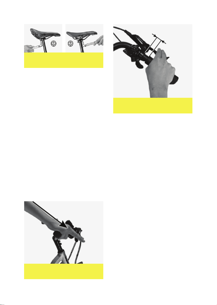
1. Loosen the two screws that hold the
saddle and seat post using a 5 mm
allen key (see Figure 9) until the
saddle can move easily.
2. Adjust the angle and setback of the
saddle as suits you.
3. Tighten each screw a half-turn,
alternating between the two,
without going over the maximum
torque level that is indicated next
to them.
4. Check that the saddle is correctly
in place and that there is no play.
Figure 5. Tightening / loosen
single saddle bolt.
06

Figure 7. Brake lever aligned with
the forearm.
E. SETTING BRAKE LEVER POSITION
Our bikes are already set up to oer you
optimal ergonomics. However, if you wish
to adjust your cockpit, we advise you to
proceed as follows:
1. To ensure a good lever position,
loosen the screw(s) holding the lever
onto the brake attachment, then
adjust the angle so that it is in line
with your forearms when you are in
riding position. (see Figure 7)
2. Adjust the distance of the brake
lever from the grip in order to easily
use the brake lever with two ngers.
(see Figure 8)
3. Retighten the screws on the brake
attachments to 6 Nm. For any other
adjustment, check the dedicated
notice or consult your retailer.
F. HEADSET
The headset is made up of two bearings
and cups placed at each end of head tube.
The Zero bike has an “A-head“ head set:
this is adjusted using the round hood
which is found above the stem.
(as in Figure 9)
During more intense rides, the headset is
put under incredible stress. It is therefore
possible that play will develop.
Be careful, riding with any play in your
head set can deteriorate your head set
and even your frame.
In order to check if your head set is in
good shape, there are two simple tests
that should be carried out before you
ride:
TEST 1 - With the front brake on, try to
move your bike forward and back. You
will immediately notice if there is a high
level of play or not.
Figure 6. Tightening / loosen
single saddle bolt.
Figure 8. Distance between lever
and grip.
07

TEST 2 - Make the front wheel of your bike
bounce. You will hear a sharp loud noise only
if there is signicant play in the head set.
Pay attention to other noises, such as those of
the cables hitting against the frame, or even
the spokes. Do not take these into account.
If you have found play in the head set,
follow these steps:
1. Loosen the screw(s) on the stem.
(see Figure 9)
2. Then progressively tighten,
without forcing, the screw in the
hood until play disappears as in
stage 2. (see Figure 12)
3. Check that play in the fork is no
longer present. The fork should turn
easily and you should not feel any
friction or resistance when it turns.
4. Retighten the screw(s) on the stem
following the recommended torque
setting of 5 Nm. (see Figure 10)
Figure 9. Headset tightening step
one loosen stem screws then
tighten the top cap.
Figure 10. Retighten the stem bolts
to 5 Nm.
A. FITTING PEDALS
To install your pedals, follow these steps:
1. Put a small amount of mounting
grease (you can nd this at your
local bike retailer) on the thread of
each pedal.
2. Tighten the right pedal (marked «R»
on the pedal, see Figure 13) in a
clockwise direction on the crank
on the drive side.
3. Tighten the left pedal (marked «L»
on the pedal, see Figure 14) in an
anti-clockwise direction on the
crank on the left side.
4. The recommended torque is 30 Nm.
PEDALS
Figure 13. Pedal threads. Make sure
you rotate the correct direction
08

WHEEL AXLES
Figure 12. Front Quick Release Axle
1. Shaft
2. Nut
3. Lever
4. Conical spring
2. Loosen the nut on the other side of
the axle by hand until there is
sucient play that you are able to
remove the wheel (It is not
necessary to remove the axle from
the wheel hub).
3. Take o the wheel.
C. PROCESS TO FOLLOW FOR
RELIABLE
TIGHTENING OF THE WHEEL WITH
QUICK RELEASE AXLES
If you want to tighten the wheel of your
Zoomo Sport, please follow this process:
1. Check that the lever is in the open
position (You should be able to
read « OPEN » that is engraved on
the lever).
2. Check that the conical springs are
on each side of the hub and that
the smallest circumference of
these is oriented towards the
center of the wheel as in Figure 14.
3. Place the wheel on the fork or the
frame, checking that the axle is
fully placed into the dropouts of
the frame or fork. The wheel
should be centered, as should the
disc in the caliper.
4. Hand tighten the tightening nut
until it touches the fork or frame
Figure 13. Stages of opening the
quick release axle.
WARNING! Wheel axles are essential
safety elements on your bike. Please
respect the information below, otherwise
you risk losing parts and falling.
A WHEEL BADLY TIGHTENED OR BADLY
CENTERED CAN CAUSE ACCIDENTS AND
SERIOUS INJURY TO THE USER.
A. FRONT QUICK RELEASE AXLE
A quick release has been designed to be
easily adjusted with your hand. Never use
a tool to block or release the mechanism in
order not to damage it. To fully understand
the steps below, you need to know the
names of the parts making up this quick
release axle:
B. OPENING THE QUICK
` RELEASE AXLE
If you want to remove the wheel of your
Zoomo Sport, please follow this process:
1. Open the axle’s lever. You should
now be able to read the
engraved « OPEN » on the lever
as in Figure 13.
09

The adjustment of your derailleur was
carried out before delivery of your bike
and therefore, you should not need to do
it yourself. If however, you feel you need
to intervene with its settings, perhaps
because of cable stretch, we advise you
to consult your local approved retailer.
With a little bit of experience, you can
also follow the stages below:
1. In order to adjust the low and high
speed stop screws, it can be
easiest to unscrew the cable
tightener and set the derailleur in
the highest gear. You can then
push against the derailleur with
your hand.
2. The upper tensioner should be
aligned with the high or low cog
when the derailleur is in high or
low speed setting. If the tensioner
is not aligned, you must tighten or
untighten the stop screw to obtain
he correct setting (see Figure 16).
DERAILLEUR
3. Then you must adjust the
indexing. Ensure that the gear
changing lever is set to the
highest gear, which corresponds
to the smallest cog. Then tighten
the cable by pulling on it and
immobilize it by using the cable
tightener on the derailleur.
To perfect the cable tension, use the dial on
the derailleur or on the lever. When pressing
on the lever to change up the gears, the
derailleur should climb without delay onto
the next cog without making any noise.
5. Reclose the quick release lever with
the palm of your hand parallel to the
fork or the frame dropout ensuring
you have the recommended level of
tightness. The engraving « CLOSE »
is now visible. The recommended
tightness is obtained when the lever
hardens midway through the course,
that’s to say from the moment when
the lever nds itself in line with the
axle. If the lever is too hard to close,
you can loosen the nut on the axle.
If the lever is not tight enough, you
can retighten the nut until the
correct level is attained.
If the lever is not tight enough, you
can retighten the nut until the
correct level is attained.
Figure 14. Stages of tightening
the axle.
Figure 16. Derailleur stop screws setting.
10

If the derailleur does not pull the chain
onto the next cog, or if it makes noise
from rubbing onto the lower cog, you
need to tighten the cable by unscrewing
the dial. Inversely if the derailleur takes
the chain too far, climbing up two cogs or
rubbing on the upper cog, you need to
loosen the cable by tightening the dial.
The nal adjustment to cut out all noise
should be precise and the dial adjusted by
a quarter turn between each check.
For optimal durability and functioning,
check the specic notices of each
manufacturer delivered with this manual
in order to correctly carry out the settings
and maintenance of components. Also
ensure you adapt the settings to your size
and your type of riding.
WARNING! A badly carried out setting
can make you lose control of your
Zoomo or damage components. Ask
your local retailer for advice. He/she has
the necessary experience to help you
nd the correct settings. You can also
refer to the manufacturer’s notice.
A. FORK LOCKOUT SYSTEM
Some forks are equipped with a system to
lockout the suspension. Each brand has
its own type of lockout but the principle
remains very similar from one brand to
another. When the system is locked, the
fork movements are blocked in order to
guarantee better pedaling eciency.
However, the fork is not 100% blocked in
order not to damage the suspension if the
fork stays locked out on rough ground.
The levers are on the right leg of the fork.
SUSPENSION
The following gure presents dierent
models of lockout systems.
Figure 17. Dierent systems of
fork lockouts.
- To unlock a suspension fork
turn the locking lever in the
direction indicated by the
arrow with the description
« OPEN » until it stops. (See
the example on Figure 18).
- To lock a suspension fork,
turn the locking lever in the
direction indicated by the
arrow with the description
« LOCK » or « FIRM » until it
stops. (See the example on
Figure 19).
WARNING! If despite these
recommendations you are not able to
correctly index your gears, see your
local retailer so they can carry out the
dierent steps of adjustment as well as
checking the derailleur hanger.
11

B. SETTING THE PRE-STRESS OF
THE FORK (SAG)
In order to fully prot from your bike’s
potential, the suspension should be set up
for your weight. This is a technical
procedure that can be carried out by your
local retailer if you do not have the
necessary knowledge or material.
This setting is commonly called « SAG »,
which corresponds to the compression of
the suspension under the weight of the
cyclist. The level of SAG varies according
to the type of fork and the type of usage
of the bike.
The SAG is a value expressed as a
percentage, and denes the length of
displacement of the stanchions in relation
to the fork or shock body, caused by your
body weight when you are sitting on the
bike. Let’s take an example:
My fork has 140 mm of travel (which
means the stanchions are 140mm long).
The recommended SAG is 25%.
To convert this SAG value into millimeters
you just need to use the following formula:
SAG [in mm] = SAG [en %] x Travel [in mm]
Which in this example case gives us: SAG
[in mm] = 25% (0.25) x 140 mm = 35 mm
So, my body weight pushes the
stanchions into the legs by 35 mm.
The SAG is calibrated by setting the
pre-stress of the shock or the air pressure
in the pneumatic cartridge depending on
the type of fork. To set up fork SAG carry
out the following steps:
For Coil spring with oil damping
- Sit on the bike in a normal position
and wear your usual riding kit
(helmet, bag and accessories…).
You can lean against a wall in order
to avoid any brusque movements
on the bike.
Figure 18. Locking lever in
open position.
Figure 19. Locking lever in
close position.
12

- Step o your bike gently to avoid a
harsh movement and measure the
“SAG”. A SAG that is too weak
indicates that the pre-stress of the
spring is too high. You should
therefore turn the adjustment lever
towards the « -». Inversely, a too
high level of SAG indicates that the
spring’s pre-stress is too weak, and
you should therefore turn the
adjustment lever towards « +».
- Repeat these steps until you nd
the right level.
Hint: If your fork is not equipped with a
rubber O-ring that you can use to see the
SAG position, you can place a plastic zip
tie on the fork stanchion which will carry
out the same function.
Other settings can be carried out so you
prot as much as possible from your
suspension system. Refer to the dedicated
notice or to your local bike retailer.
For suspension models with
Air/Oil cartridge system
Before starting, ensure you have a high
pressure pump and your usual riding gear.
- Place the rubber O-ring against the
fork leg.
- Sit on the bike in a normal position
and wear your usual riding kit
(helmet, bag and accessories…).
You can lean against a wall in order
to avoid any brusque movements
on the bike.
- Step o your bike gently to avoid a
harsh movement and measure the
“SAG” (see gure 20). A SAG that
is too weak indicates that there is...
Figure 20
too much pressure in your fork.
You should therefore take out air
from your suspension. Inversely, a
too high SAG indicates that there is
not enough, you should therefore,
add air.
To do this:
- Unscrew the valve cap to access
the fork valve that enables you to
adjust the air pressure as in the
following gure:
- Using a high pressure pump, adjust
the fork’s air pressure in order to get
the desired SAG as in the gure
above. Be careful to not pass the
maximum air pressure that your
fork can handle! This value can be
found In the manufacturer’s notice.
- Sit on the bike as described
previously and check the SAG.
Repeat these steps until you nd
the right level.
Hint: If your fork is not equipped with a
rubber O-ring that you can use to see the
SAG position, you can place a plastic zip
tie on the fork stanchion which will carry
out the same function.
Other settings can be carried out so you
prot as much as possible from your
suspension system. Refer to the dedicated
notice or go to your local bike retailer.
13

C. CLEANING
- Make sure you clean the stanchions
after each usage, with a little soapy
water and a soft sponge.
- Then wipe all the surfaces with a
soft cloth.
- Carefully inspect all the seals,
these guarantee the correct
functioning of your forks and
above all their reliability.
Some of the maintenance of your fork,
such as lubrication and purging should be
carried out following the specic
recommendations of the manufacturer
(for this you need to refer to the notice
produced by the manufacturer). These
operations should be entrusted to a
specialist.
BRAKE ADJUSTMENT
Undo the pad retaining bolt using a M3 hex
tool.
Figure 21. Undo the mount bolts to
remove calliper.
WARNING! Please ensure that your
brakes are correctly setup for your
region. Do not ride the bike until you
have checked this. To check, hold on the
right hand brake at full lock. Push the
bike forward until you can identify the
wheel which is not moving.
AUSTRALIA - Right Hand is Front Brake,
Left Hand is Rear Brake
UK - Right Hand is Front Brake, Left Hand
is Rear Brake
USA - Left Hand is Front Brake, Right
Hand is Rear Brake
FRANCE - Left Hand is Front Brake, Right
Hand is Rear Brake
A. PAD REPLACEMENT
The brake pads should be replaced every
3 months or 1800kms (whichever comes
rst). To start, undo the two x m5 bolts on
the brake calliper mount.
14

Gently push out the pad from the holder
using your allen wrench. Once free of the
calliper, the pads and the connecting
spring can be separated.
Figure 22. Undo pad retaining bolt.
The retaining clip can now be separated
from the pads. Insert the new pads into
the retaining clip and reinstall the pads.
Figure 23. Undo the mount bolts to
remove calliper.
Figure 24. Undo pad retaining bolt.
15

STARTING / SHUTDOWN OF THE SYSTEM
A. PRESS AND HOLD ‘ON’ BUTTON
Some forks are equipped with a system to
lockout the suspension. Each brand has
its own type of lockout but the principle
remains very similar from one brand to
another. When the system is locked, the
fork movements are blocked in order to
guarantee better pedaling eciency.
However, the fork is not 100% blocked in
order not to damage the suspension if the
fork stays locked out on rough ground.
The levers are on the right leg of the fork.
B. ACTIVATE THE DISPLAY
Press the display ‘on button’ which is on the
handlebar control pad. This will activate
the display which will start counting down
from 30 seconds.
C. SCAN KEY
Scan the RFID Key to Activate the System.
D. CHARGING AN EXTERNAL
USB DEVICE
Add a USB cable to charge a phone or device.
E. OPERATING PEDAL ASSIST MODES
The Sport has ve levels of pedal assist.
Level 1 is the lowest level, level 5 is the
highest. Battery drain is higher in the
levels 4 and 5 with three being a good
balance for range and power. You can
select your pedal assist level by using the
up and down arrows.
16

To convert this SAG value into millimeters
you just need to use the following formula:
SAG [in mm] = SAG [en %] x Travel [in mm]
Which in this example case gives us: SAG
[in mm] = 25% (0.25) x 140 mm = 35 mm
So, my body weight pushes the
stanchions into the legs by 35 mm.
The SAG is calibrated by setting the
pre-stress of the shock or the air pressure
in the pneumatic cartridge depending on
the type of fork. To set up fork SAG carry
out the following steps:
For Coil spring with oil damping
- Sit on the bike in a normal position
and wear your usual riding kit
(helmet, bag and accessories…).
You can lean against a wall in order
to avoid any brusque movements
on the bike.
A. SHUTDOWN WITH MOTOR
LOCK ENGAGED
The bike is tted with an electronic motor
lock which is a strong anti theft feature.
This is engaged by default when the bike
is shut down using the display. The condition
is removed when the system is restarted
as per Step 1 using the RFID key.
This can be used if the bike needs to be
ridden by the owner as a regular bike
without assistance.
SHUTTING DOWN THE BIKE
Note: The display will timeout after 10
minutes for security reasons.
There is an option (2b) which details
shutting down the bike without the motor
lock engaged. To do this, shut the battery
down before you shut down the display.
Press and hold the battery button with
the display still on to shut down without
motor lock.
Press and hold the battery button until
the light goes o
17

- Step o your bike gently to avoid a
harsh movement and measure the
“SAG”. A SAG that is too weak
indicates that the pre-stress of the
spring is too high. You should
therefore turn the adjustment lever
towards the « -». Inversely, a too
high level of SAG indicates that the
spring’s pre-stress is too weak, and
you should therefore turn the
adjustment lever towards « +».
- Repeat these steps until you nd
the right level.
Hint: If your fork is not equipped with a
rubber O-ring that you can use to see the
SAG position, you can place a plastic zip
tie on the fork stanchion which will carry
out the same function.
Other settings can be carried out so you
prot as much as possible from your
suspension system. Refer to the dedicated
notice or to your local bike retailer.
For suspension models with
Air/Oil cartridge system
Before starting, ensure you have a high
pressure pump and your usual riding gear.
- Place the rubber O-ring against the
fork leg.
- Sit on the bike in a normal position
and wear your usual riding kit
(helmet, bag and accessories…).
You can lean against a wall in order
to avoid any brusque movements
on the bike.
- Step o your bike gently to avoid a
harsh movement and measure the
“SAG” (see gure 20). A SAG that
is too weak indicates that there is...
ZOOMO BATTERIES
Returning the battery into the cradle. Ensure
the battery is pushed down into the cradle
until you hear a ‘click’. The battery should be
clearly locked in position with no movement.
CHARGING THE BIKE
Plug the socket into the battery before
plugging into the wall to initiate charging.
The battery will charge to 100% in around
2.5 hours.
WARNING!
!The battery may require a small
amount of force to remove the battery
from the frame. Hold the battery rmly
when removing it, to make sure the
battery does not slip from your hands
when it suddenly comes loose.
! Remove the key after placing the
battery. The key can be easily damaged
if left in.
! Batteries drain energy slowly, even if
the bicycle is not used. If the battery is
connected to the bike it will run out of
power faster than if it is taken out and
stored inside.
! During maintenance, always remove
the battery.
! Use only the supplied charger. Use
your charger only in dry, well ventilated
places. The battery charger is not
resistant against moisture and/or drop
down shocks.
! After charging, always disconnect the
charger from the mains as well. This will
increase the lifetime of the charger and
prevent charging issues the next time
you connect the battery.
1. REMOVING THE BATTERY
The bike's battery can be removed from
the bike for storage and charging. To
remove the battery turn the key and the
battery will pop out of position in the frame.
18
Other manuals for Sport
1
Table of contents
Other Zoomo Bicycle manuals