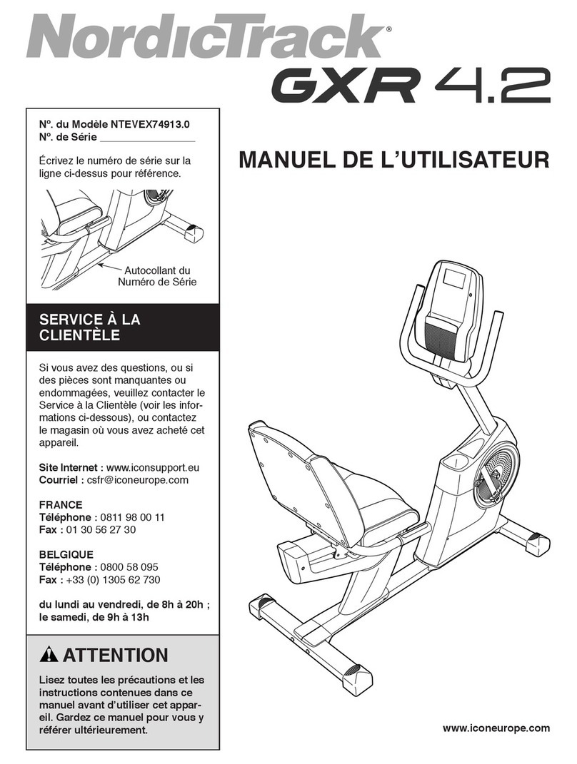
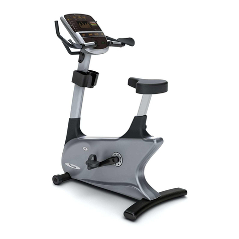
CIRCLE FITNESS B-7 SERIES Quick start guide

Document NO.
B-7A-EM-English
PAGE Page 1 of 14
Engineer Manual-Trouble Shooting
VERSION A
ENGINEER MANUAL FOR
AFTER SALE SERVICE
PRODUCT:UPRIGHT BIKE
MODEL: B-7 SERIES A TYPE

Document NO.
B-7A-EM-English
PAGE Page 2 of 14
Engineer Manual-Trouble Shooting
VERSION A
INFORMATION GUIDE:
1. Problem Check Steps And Sol tions
1.1 No Resistance ----- Page 3~5
1.2 No Any Display On Console(No Power) ----- Page ~8
1.3 Can Not Keep Display While Stop Paddling ----- Page 9
1.4 Too Heavy Or Light Resistance ----- Page 9
1.5 Abnormal Display On Console ----- Page 10
1. Membrane Key Lose Function ----- Page 10
2. Information For Components
2.1. Resistance Control Board ----- Page 11
2.2. Console Wire ----- Page 12
2.3. Battery ----- Page 13
2.4. Membrane Key ----- Page 13
3. Engineering Mode
3.1. Engineering Mode ONE: Factory Settings ----- Page 14
3.2. Engineering Mode TWO: Used Information Management ----- Page 14

Document NO.
B-7A-EM-English
PAGE Page 3 of 14
Engineer Manual-Trouble Shooting
VERSION A
1. Problem Check Steps And Sol tions
1.1. 【No Resistance】:Press START and adjust the LEVEL by press UP or DOWN key, but no
any change on the resistance.
※ If this is a all new product that just finished assemble, there are more possibly in
assemble problems, maybe connect wire not well or wire damaged while assemble.
Steps illustrate:
Step
illustrate Auxiliary Photo
1
Start to p
addling and press START to begin.
Check RPM on window, Is it work or show
“0”?
Worked:Execute step 2~ .
Show “0”:Execute step 2~3 & 7.
2
Check the console wire connection well
when assemble. Re-check the resistance
function after check or re-connect or
replace the console wire.
Refer to: 2.2『Console Wire』
3
To open the housing a side.
Take off the crank fixed screw.
Take off the crank.

Document NO.
B-7A-EM-English
PAGE Page 4 of 14
Engineer Manual-Trouble Shooting
VERSION A
Step
illustrate Auxiliary Photo
3
To open the housing a side.
Take off the screws.
Take off the housing.
Fix back the crank.

Document NO.
B-7A-EM-English
PAGE Page 5 of 14
Engineer Manual-Trouble Shooting
VERSION A
Step
illustrate Auxiliary Photo
4
Start to paddling and press START to begin.
Check the pilot lamp LED3 where on the
resistance control board.
Is it light up? It shall be light up or
flash depend on paddling speed and level
in the normal condition.
5
If LED3 light up normal, please replace the
resistance control board.
Check resistance again after replace
control board.
If LED3 did not light up, it is mean the
console did not send signal down to the
control board, please check console wire
first. Otherwise, replace the console PCB.
Refer to:
2.1『Resistance Control Board』
2.2『Console Wire』
7
Start to paddling, check the pilot lamp
LED4 where on the resistance control
board. Is it light up?
It shall be light up when paddling.
If it did not light
up, please replace the
control board.
If it light up but no RPM display, please
replace the console PCB.

Document NO.
B-7A-EM-English
PAGE Page 6 of 14
Engineer Manual-Trouble Shooting
VERSION A
1.2. 【No Any Display On Console(No Power)】:No any display on console when paddling.
※ If this is a all new product that just finished assemble, there are more possibly in
assemble problems, maybe connect wire not well or wire damaged while assemble.
Steps illustrate:
Step
illustrate Auxiliary Photo
1
Check the console wire connection well
when assemble. Re-check the resistance
function after check or re-connect or
replace the console wire.
Refer to: 2.2『Console Wire』
2
Open the console housing.
Take off the screws.
Dis-connect the console wire.
Connect back the console wire

Document NO.
B-7A-EM-English
PAGE Page 7 of 14
Engineer Manual-Trouble Shooting
VERSION A
Step
illustrate Auxiliary Photo
3
Start to paddling.
To measure the power supply component
where on the console PCB by multi-meter.
It shall have about 12Vdc input and 5Vdc
output in the normal condition.
If there is no 12Vdc power input, please
execute step 3~8.
If there is no 5Vdc power output, please
replace the console PCB.
4
Take off the console and check the console
wire connection well.
Refer to: 2.2『Console Wire』
5 To open the housing a side.
According to 1.1.【No Resistance】step 3
Start to paddling, check pilot lamp LED1
where on the resistance control board.
It shall be light up when paddling.

Document NO.
B-7A-EM-English
PAGE Page 8 of 14
Engineer Manual-Trouble Shooting
VERSION A
Step
illustrate Auxiliary Photo
7
If LED1 did not light up when paddling, to
measure the terminal JK1 where on the
control board when paddling.
It shall have AC voltage and the value high
or low depend on paddling speed, paddling
faster the voltage will be higher.
8
If there have AC voltage, please replace
the control board then check again.
If no voltage, please check the generator
power wire connection well and generate
normal.
9
Start to paddling and check the pilot lamp
LED2 where on the control board.
It shal
l be light up when paddling and will
has a “Da“ sound come from relay.
If LED2 did not light up, maybe do not send
the signal from console, please replace
the console PCB first and check.
Otherwise, please replace resistance
control board and re-check again.

Document NO.
B-7A-EM-English
PAGE Page 9 of 14
Engineer Manual-Trouble Shooting
VERSION A
1.3. 【Can Not Keep Display While Stop Paddling】:
Steps illustrate:
Step
illustrate Auxiliary Photo
1 To open the housing a side.
According to 1.1.【No Resistance】step 3
2 Replace the battery.
Refer to: 2.3『Battery』
1.4. 【Too Heavy Or Light Resistance】:
※ Product execute the calibrate procedure already in the factory, if adjust the device
to increase or decrease the resistance, each level will be more heavy or light and will
deviate at watt and calories display.
Steps illustrate:
Step
illustrate Auxiliary Photo
1
If resistance keep on the heavy condition
when press UP or DOWN to adjust the level
,
please pull out the console wire from
console and paddle again.
If the resistance still keep heavy, please
replace the resistance control board, if
resistance become light, please replace
the console PCB.
2
If resistance adjust normal by press UP or
DOWN but feel too heavy or light, please
execute the resistance adjust procedure as
below.
3 To open the housing a side.
According to 1.1.【No Resistance】step 3
4
Start to paddling and press START to begin.
Adjust the variable resistor where on
resistance control board.
Turning clockwise to heavier or
anticlockwise to lighter.

Document NO.
B-7A-EM-English
PAGE Page 10 of 14
Engineer Manual-Trouble Shooting
VERSION A
1.5. 【Abnormal Display On Console】:
Steps illustrate:
Step
illustrate Auxiliary Photo
1
Start to paddling and press START to begin.
If all functions are fine but display,
please replace the console PCB.
1. . 【Membrane Key Lose Function】:
Steps illustrate:
Step
illustrate Auxiliary Photo
1 To open the console housing.
To execute the step 2 of 1.2【
No Any Display
On Console(No Power)】
2
Start to paddling and press START then pull
off the membrane key connector from
console PCB. To refer to the PIN table of
2.4『Membrane Key』, to find PINs on co
nsole
PCB that got problem while operate and
short them.
If no function when short the PINs, please
replace the console PCB.
If normal function when short the PINs,
please replace the membrane key.
For example:
UP key no function, to short
the PIN no.5 & to check the function
without use membrane key.

Document NO.
B-7A-EM-English
PAGE Page 11 of 14
Engineer Manual-Trouble Shooting
VERSION A
2. Information For Components
2.1. Resistance Control Board
2.1.1.Appearance and connector description:
2.1.2.Description of pilot lamps on Control Board:
LED1: Main power pilot lamp, lights up when paddling.
LED2: Console PCB power input pilot lamp, lights up while console display.
LED3: PWM out put pilot lamp, lights up while output resistance.
LED4: RPM pilot lamp, lights up when paddling.
Console wire
Battery
External power
Generator power
source input
Coil power
output

Document NO.
B-7A-EM-English
PAGE Page 12 of 14
Engineer Manual-Trouble Shooting
VERSION A
2.2. Console Wire:Check all connect certainty and outward completely.
Step
illustrate Auxiliary Photo
1 Take off the console and pull out the
console wire connector plug.
2 Check connector internal PINs, it shall
not be crooked.
3 Check connector internal PINs, it shall
not be draw back.
4
Check the wires outward, it shall not be
crush injuries or breakage.
Take off the screws.
Dis-connect the console wire.

Document NO.
B-7A-EM-English
PAGE Page 13 of 14
Engineer Manual-Trouble Shooting
VERSION A
2.3. Battery:
Step
illustrate Auxiliary Photo
1 To measure the battery, it
shall be have
12~13Vdc。
2.4. Membrane Key:PINs definition
PIN P1 P2 P3 P4 P5
P Display Down( ) START Enter UP( )
P1P6

Document NO.
B-7A-EM-English
PAGE Page 14 of 14
Engineer Manual-Trouble Shooting
VERSION A
3. Engineering Mode
3.1. Engineering Mode ONE: Factory Settings
3.1.1.Console no power condition, press START and UP simultaneously and start to
paddling, To leave you hand from keys till dot-matrix window show WELCOME.
3.1.2.LED will do the scan mode after dot-matrix window show WELCOME, then dot-matrix
will show『BM010 FACTORY SETTINGS PRESS ENTER』.
3.1.2.1. Press ENTER to select model type:Dot-matrix window show EP-7000, press
UP or DOWN to change the model type to EP-5000 or B-7000.
3.1.2.2. Press ENTER to set the unit:Dot-matrix window show『UNITS ENGLISH』,
press UP or DOWN to change to『UNITS METRIC』。UNITS ENGLISH:mile、LB.
UNITS METRIC:km/h、kg. Press ENTER back to idle mode.
3.2. Engineering Mode TWO: Used Information Management
3.2.1.Console no power condition, press START and DOWN simultaneously and start to
paddling, To leave you hand from keys till dot-matrix window show WELCOME.
3.2.2.The dot-matrix window show software version information, TIME window show total
used time 00:00(m:s) ~9999(h), DISTANCE window show total used distance 0.0 ~
999. Press ENTER back to idle mode.
Table of contents
Other CIRCLE FITNESS Exercise Bike manuals
CIRCLE FITNESS
CIRCLE FITNESS E7 User manual

CIRCLE FITNESS
CIRCLE FITNESS Sp8 User manual

CIRCLE FITNESS
CIRCLE FITNESS R8 User manual

CIRCLE FITNESS
CIRCLE FITNESS E7 User manual

CIRCLE FITNESS
CIRCLE FITNESS R6 User manual

CIRCLE FITNESS
CIRCLE FITNESS E7 User manual

CIRCLE FITNESS
CIRCLE FITNESS Sp7 User manual

CIRCLE FITNESS
CIRCLE FITNESS B8 E User manual

CIRCLE FITNESS
CIRCLE FITNESS R8 User manual