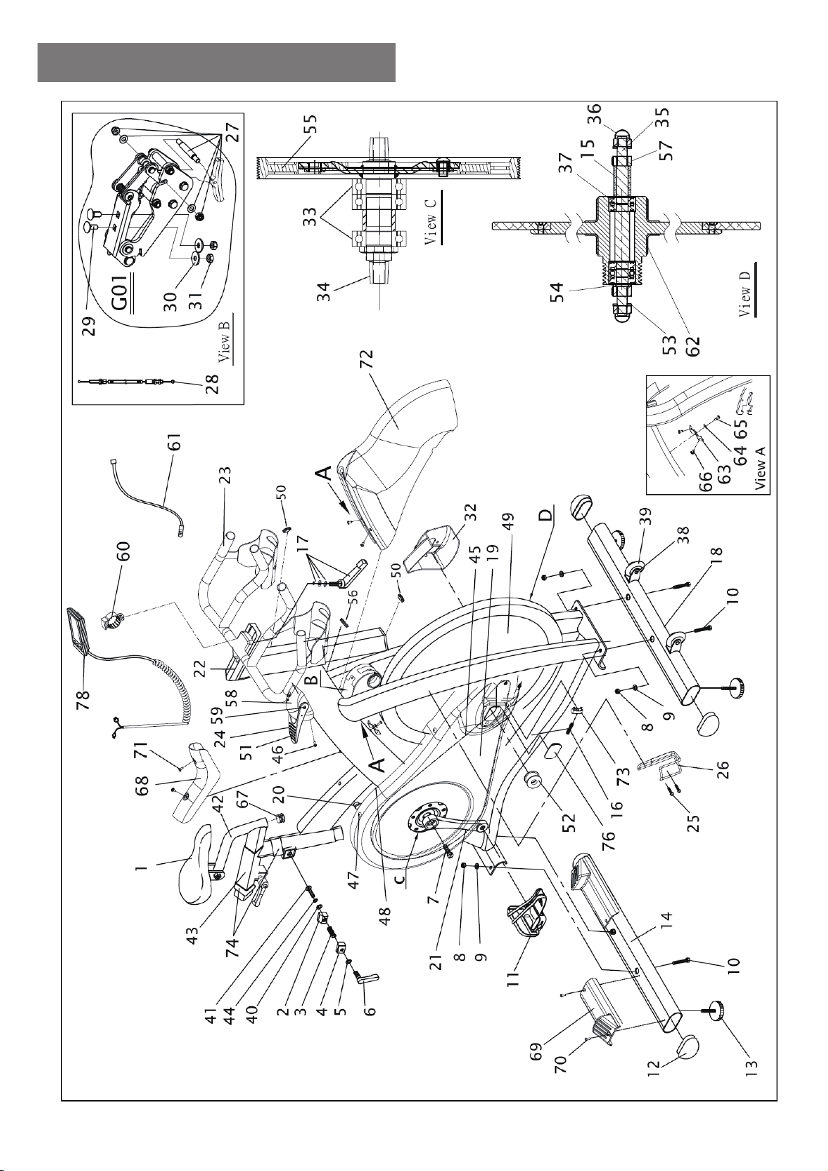
CIRCLE FITNESS Sp7 User manual

Sp7 (Premium version)
Indoor Cycle
Owner’s Manual


ATTENTION:
Read instructions carefully, failure to do so may cause permanent damage to your bike.
Please verify that all parts associated with thisproduct are in good condition and accounted for.
During the assembly process please be sure to follow each step accordinglyasit hasbeen
explained within the manual.
1
S831102-000-00 Sp7(Premium version) 10807

SAFETY INFORMATION:
1. Keep children and pets away from this equipment at all times. DO NOT leave them
unsupervised in the room where the machine is kept.
2. If you experience dizziness, nausea, chest pains or any other symptom while using
this machine STOP the exercise. SEEK IMMEDIATE MEDICAL ATTENTION!
3. Keep your hands away from any of the joints and moving parts.
4. Wear clothing suitable for doing exercise. Do not wear baggy clothing that might get
caught in the machine. Always wear athletic shoes when using the machine and tie
the laces securely.
5. This machine must only be used for the purposes described in this manual. DO NOT
use accessories that are not recommended.
6. Do not place sharp objects near the machine.
7. Any person with physical or coordination limitations should not use the machine
without the assistance of a qualified per son or doctor.
9. Do not use the machine if it is not working correctly.
10. Before using the machine, thoroughly inspect the equipment for proper assembly.
11. Use only authorized and trained technicians if a repair is needed.
15. Use only the tools provided to assemble this machine.
16. This machine can only be used by one person at a time.
17. The moving pedals can cause injury.
Caution: Consult your doctor before beginning to use the machine or any exercise
program. Read all of the instructions before using any exercise equipment.
KEEP THESE INSTRUCTIONS SAFE FOR FUTURE USE.
2

CAUTION: During assembly it is recommended that all bolts be tightened by hand,
upon completing assembly, bolts should then be properly secured using the wrench
provided. To avoid injury, check bolts carefully before use.
Assembly
Step one
Attach the rear foot tube (14) first by lifting up
the rear of the frame and sliding the rear foot
tub under the frame. Align the holes of the
tube and frame then insert bolt (10) from
below. Secure the bolt with washer (9) and nut
(8) use the wrench. Use the same procedure
to secure the front foot tube (18).
Attach the top protect cover (68) to the frame
usin
g
the bolts
(
71
)
to fixed.
Step two
Attach the handlebar post (22) by inserting it
into the head tube on the frame. Make sure
the release lever (6) is loose enough so the
handlebar post can slide down to the desired
position. Tighten the release lever (6) to
secure.
Attach the handlebar slider (23) on the top of
handlebar post (22), make sure secure by
tighten the release lever (17) from below.
3

Step three
Attach the saddle (1) onto seat slider (42),
and secure the saddle by tightening the nuts
on both sides of the saddle clamp on the
underside of the saddle, use wrench.
Slide the seat slider (42) into the seat post
(43) adjust to desired position and secure
with the release lever (6) on the bottom of
the seat post (43).
Slide the seat slider (42) into the seat post
(43) adjust to desired position and secure
with the release lever (6) on the bottom of
the seat post (43).
Step four
Attach the pedals (11) into the crank arms
(20)(21), each pedal is marked with L (left) or
R (right) to denote the side of the spinning
bike they are on.
Note - the right hand crank is on the same
side as the belt guard (19). Be careful to
align the threads correctly to avoid
damaging them. Tighten using a 15mm
spanner; both pedals should tighten towards
the front of the spinning bike.
Screw the Clamp (60) on the Handlebar, and
attach the Console (78) on it, then connect
the sensor cable (61) which coming from
main frame with console cables which
coming from handle bar post bottom.
In addition, plug the connector back into the
frame hole and make sure that the cable
stopper (56) is plugged into the hole.
Unscrew the screw (25) on the right fork.
Align the holes of the water bottle cage (26)
with the holes on the fork and secure with
two screws (25).
4

Remark:
Riding this bike backwards may loosen the pedals which will damage the threads.
Please always check pedals to ensure that the pedals are tightened. If the pedals
have become loose, tighten threads with the wrench supplied to ensure they are
securely attached.
Right Pedal
Please make sure pedal in your hand is the right pedal before
Installation. Please refer to the figure. Align the right pedal with
right crank at 90 degree. Gently insert the pedal in the crank arm.
Turn the pedals clockwise as tightly as you can with your hand.
Use the wrench to ensure it is tightened securely. Please always
tighten by hand first, then finish by wrench.
Left Pedal
Please make sure pedal in your hand is the left pedal before
Installation. Please refer to the figure. Align the left pedal with left
crank at 90 degree. Gently insert the pedal in the crank arm. Turn
the pedals counter- lockwise as tightly as you can with your
hand. Use the wrench to ensure it is tightened securely. Please
always tighten by hand first, then finish by wrench.
5

Stability
If the floor is not even, you can adjust the
height by foot tube adjuster pad (13) to make it
firmly.
Adjusting the resistance
Adjust the exercise resistance on the spinning
bike which using the RED LEVER (51) of the
Tension knob (24) to work with Level 1-16
(loosen to tighten).
The flywheel should rotate freely without
resistance when you loosen the Tension knob
fully (Level 1).
More experienced riders may wish to increase
the overall resistance by increasing the number
of the Levels.
This bike can be stopped instantly by pushing
the red lever (51) of the Tension knob (24)
forward completely.
MOVING
There are moving wheel (39) located in front
of foot tube for easy to moving the machine.
6

Exploded Drawing
7

Part list
No. Name Unit No. Name Unit
CPleehwgnivoM93CPelddaS1
2 Alloy bind clamp ( L ) PC 40 Plastic washer for release lever PC
3 Spring for release lever PC 41 Fixed bolt for release lever PC
4 Alloy bind clamp ( R ) PC 42,67 Seat slider w/end plug PC
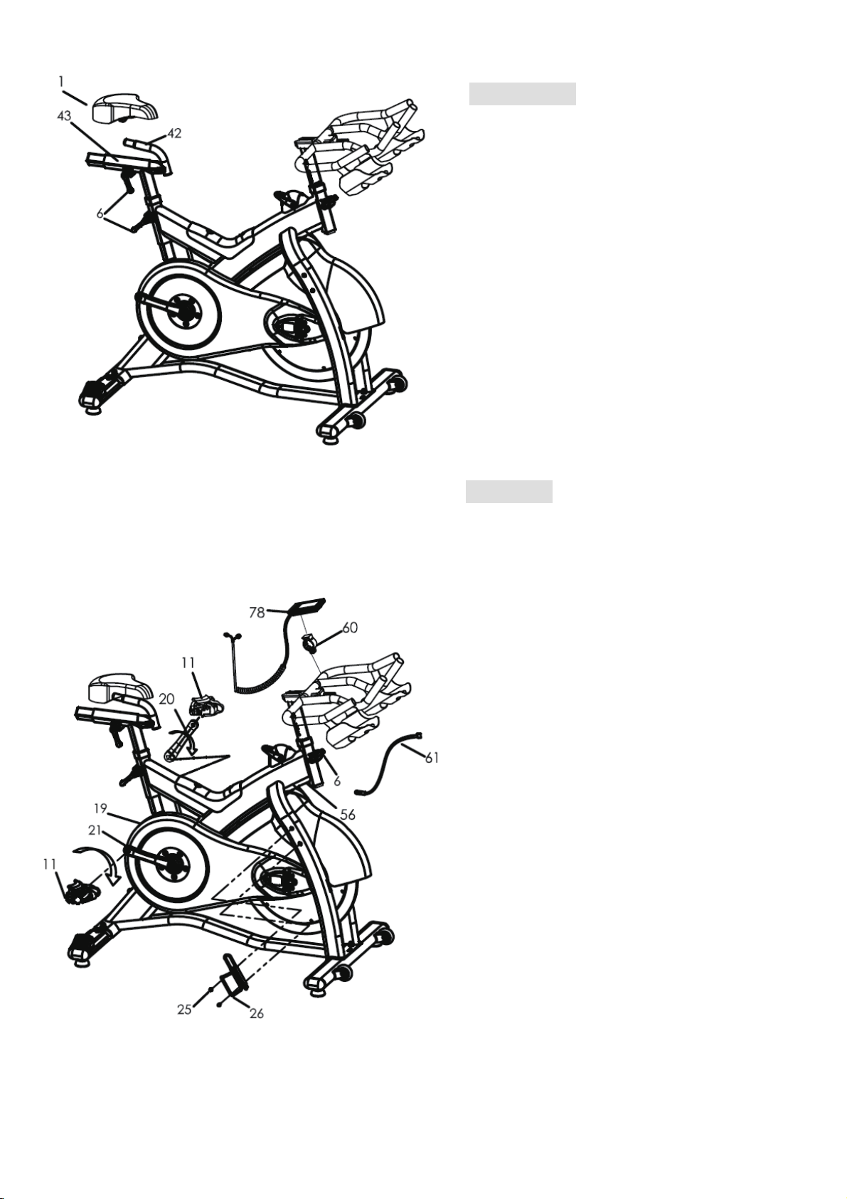
5 Washer for release lever PC 43,74 Seat post w/ Rubber sleeve PC
6 Release lever PC 44 Washer for release lever PC
CPtleB54CPtlobknarC7
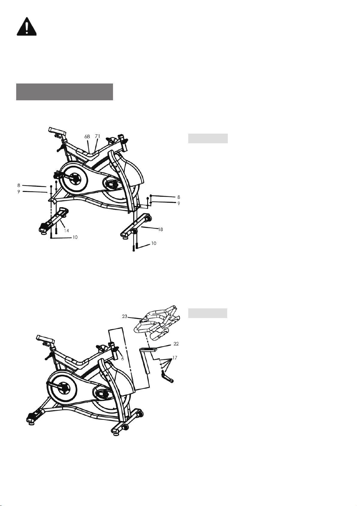
8 Foot tube nut PC 46 Fixed bolt for tension knob casing PC
9 Foot tube washer PC 47 Outer belt guard bolt PC
10 Foot fixing bolt PC 48 Inner belt guard bolt PC
TESetelpmocleehwylF94RPladeP11
12 Foot tube end cap PC 50 Rubber clip PC
13 Foot tube adjuster pad PC 51 Lever for tension knob PC
14 Rear foot tube complete SET 52 Idler w/bearing, clip SET
15 Bushing for flywheel axle PC 53 Flywheel washer PC
16,73 Flywheel adjuster plate & screw PC 54 Flywheel washer PC
17 Handle bar release lever w/washer PC 55 Belt Pulley with screw, magnet SET
18 Front foot tube complete SET56 Cable stopper PC
19 Outer belt guard PC 57 Flywheel nut PC
20 Left crank arm PC 58 Casing for tension knob PC
21 Right crank arm PC 59 Bolt for tension knob lever PC
22,50 Handle bar post w/ rubber clip PC 60 Clamp for console PC
23 Handle bar w/slider PC 61 Sensor cable PC
24 Tension knob set (complete) SET 62 Rubber cover for flywheel PC
25 Screw for bottle cage PC 63 Fixed plate for fender PC
26 Bottle cage PC 64 Washer for fixed plate PC
27 Brake pad w/holder set SET 65 Bolt for fixed plate PC
28 Resistance wire PC 66 Screw for fixed plate PC
29 Bolt for magnetic support PC 67 End plug for seat slider PC
30 Washer for magnetic support PC 68 Top protect cover PC
31 Nut for magnetic support PC 69 CPdraobhctertS
32 Left axle cover PC 70 Screw for Stretch board PC
17CPgniraebBB33 Top protect cover bolt PC
34 BB Axle with plate PC 72 CPredneF
35 Flywheel axle PC 73 Flywheel adjuster plate PC
36 Flywheel security nut
SET
74 Rubber sleeve PC
37 Flywheel bearing 76 Rubber protect cover PC
TESelosnoC87tunleehwylF75
15 Bushing for flywheel axle
rehsawleehwylF35
62 Rubber cover for flywheel
rehsawleehwylF45
38 Axle bolt for moving wheel PC
8

Saddle:
Make sure tighten enough for both side of nut
after adjust the saddle position. To prevent the
saddle from twisting side to side.
Instruction
Handlebar and seat adjustment. It is important that the
handlebar and seat are set at the correct height for your body.
Ask your instructor for assistance. Adjusting the handlebar
height-Undo the release lever that is located where the
handlebar post fits into the frame. Slide the handlebar post up
or down tothe required height and retighten the release lever.
Make sure it is securely tightened and that there is no lateral or
vertical movement of the handlebar. The handlebar position
can also be adjusted forwards or backwards. Undo the adjuster
lever located below the handlebar slider. Slide the handlebar
assembly forwards and backwards until you reach the required
position. Then securely re-tighten the adjuster lever.
Pay attention on ”MIN INSERT” mark for safety adjustment.
Adjusting the seat height- undo the adjuster lever
located where the seat post fits into the frame. Adjust
the seat to the required height. Then retighten the
release lever. The seat position can be adjusted
forwards and backwards. Undo the release lever
located directly side of the seat slider. Loosen the
release lever then slide the seat to the required
position. Then make sure the release lever retighten.
Pay attention on ” MIN INSERT” mark for safety adjustment.
Emergency Brake:
Pushing the RED lever (51) of the Tension knob (24)
forward completely for emergency brake.
9

Maintenance Chart
No DESCRIPTION Daily Weekly Monthly Quarterly Annually
1
Keep machine clean: Wipe machine
down with clean & dry fabric to clear
dirt & sweat.
X
2 Wipe Anti-rusty cream or similar on
the seat post set, handlebar set X
XkcehclausiV3
4 Check security of handle bar post &
seat post X
5 Check security of saddle X
6 Remove handlebar post and clean
tube X
7 Remove seat and clean tube X
8 Check brake pads for wear-align X
9 Check brake adjustment X
10 Check security of all knobs & release
leve
r
X
11 Check toe straps for signs of wear X
12 Check crank bolts and re-tighten X
13 Make sure pedals are screwed in X
14 Check the magnetic holder in correct
position X
15 Check belt tension, retighten when
loose X
16
K
eep flywheel clean: Wipe with
clean & dry fabric to clear dirt &
sweat.
X
17 Check bottom bracket X
18 Check flywheel bearings X
19 Full service-frame inspection X
10

How to change battery﹕﹕
1. Open battery cover and insert 2 AA or 2 UM-3 batteries.
2. Properly put back battery cover.
3. If the LCD shows partial display, please take out batteries, wait for 15 seconds and insert again.
4. Previous exercise data will be removed after take out batteries.
5. Please follow local regulationwhen through batteries away.
FunctionKeys﹕﹕
ENTER/RESET:
1. Press ENTER key to select the functions for setting exercise values of TIME and
DISTANCE.
2. Press ENTER key to confirm the set exercise values.
3. Keep pressing ENTER key for 2 seconds to remove all previous exercise data.
UP:
, DIST.
1.Press UP key to switch the functions of CAL, RPM, SPEED and PULSE, WATT
2. Press UP key to add the setting exercise values of TIME and DISTANCE.
The minimum setting value of TIME is 5 minutes. Pressing one time will add 5
minutes, for example: 0, 10, 15, 20, …..
DOWN:
1. Press DOWN key to switch MAX AVG , AVG MAX
2. Press DOWN key to decrease the setting exercise values of TIME and DISTANCE.
The minimum setting value of DISTANCE is 1 km or mile. Pressing one time will
decrease 1 km or mile, for example : 7, 6, 5, 4, 3, 2, 1…
11

UP+DOWN:
1. Press UP key and DOWN key at the same time for 3 seconds to delete date.
Functionand Operation
Auto ON/OFF
The monitor automatically starts working once the user starts to do the exercise on the machine.
It will automatically turn off after the machine is not used for around 2 minutes, and all exercise
value will be removed.
down to 0:00.
TIME
1. Press ENTER key to select TIME, and press UP/DOWN keys to set the exercise TIME.
2. If users do not set TIME, time will be automatically count up 00:00:00~99:59:59
3. Setting value of Count Down is from 5:00~99:55:00. The monitor will beep when count
SPEED
1. SPEED display range is 0.0 ~ 99.9 KPH / MPH
2. 3 SPEED display: current speed,average speed and maximum speed.
RPM
1. RPM display range is 15 ~ 999.
2. 3 RPM display: current RPM, average RPM and maximum RPM.
DISTANCE
1. Press ENTER key to select DISTANCE (TIME value is 0), and press UP/DOWN keys to
set the exercise value.
2. If users do not set DISTANCE, distance will be automatically count up 0.0~999.9 km/mile
3. Setting value of Count Down is from 1.0~999.0 km/mile. The monitor will beep when count
down to 0:00.
CALORIE
1. Calorie displays K/Cal on the LCD.
2. Calorie will be automatically count up 0.0~9999
LEVEL
Resistance Level, level display range is 1~16, monitor will detect resistance level automatically.
WATT
Watt display range is 0~999.
PULSE
1. Pulse display range is 40∼200. The Pulse value will display “P”, after user stops
measuring heart rate for 16 seconds.
2. PULSE display“ BPM” on the LCD.
3. 3 PULSE display: current heart rate, average heart rate and maximum heart rate.
Attention︰
Working Temperature︰0℃~ 50℃
Storage Temperature.︰-10℃~ 60℃
12


Sp7 (Premium version)
Indoor Cycle
www.circlefitness.com
Table of contents
Other CIRCLE FITNESS Exercise Bike manuals

CIRCLE FITNESS
CIRCLE FITNESS R8 User manual

CIRCLE FITNESS
CIRCLE FITNESS B8 E User manual

CIRCLE FITNESS
CIRCLE FITNESS R6 User manual

CIRCLE FITNESS
CIRCLE FITNESS R8 User manual

CIRCLE FITNESS
CIRCLE FITNESS E7 User manual

CIRCLE FITNESS
CIRCLE FITNESS E7 User manual

CIRCLE FITNESS
CIRCLE FITNESS B-7 SERIES Quick start guide

CIRCLE FITNESS
CIRCLE FITNESS Sp8 User manual

CIRCLE FITNESS
CIRCLE FITNESS E7 User manual