CIRCLE FITNESS Sp8 User manual

Sp8
Indoor Cycle
Owner’s Manual
Always Moving Forward


ATTENTION:
Read instructions carefully, failure to do so may cause permanent damage to your bike.
Please verify that all parts associated with this product are in good condition and accounted for.
During the assembly process please be sure to follow each step accordingly as it has been
explained within the manual.
Safety Instructions
Consult your physician before starting with any exercise program to receive advice on the optimal
training.
Warning: incorrect/ excessive training can cause health injuries. Stop using the bike when feeling
uncomfortable.
Please follow the advice for correct training as detailed in the training instructions.
Ensure that training only starts after correct assembly, adjustment and inspection of the bike.
Always start with a warm-up session.
Only use original parts as delivered.
Follow the steps of the assembly instruction carefully.
Only use suitable tools for assembly and ask for assistance if necessary.
Place the bike on an even, non-slippery surface.
For all adjustable parts be aware of the maximum position to which they can be adjusted.
Tighten all adjustable parts to prevent sudden movement while training.
This product is designed for adult. Please ensure that children only use it under supervision of an
adult.
Ensure that those present are aware of possible hazards, e.g. movable parts during training.
The resistance level can be adjusted to your personal preference.
Do not use the bike without shoes or loose shoes.
Ensure that sufficient space is available to use the bike.
Be aware of non-fixed or moving parts whilst mounting or dismounting the bike.
To protect the floor or carpet from damage, place a mat under the exercise bike.
In case of emergency please place both feet at the same time on the side reins.
Ensure that an area of 2000 x 1000 mm behind the exercise bike is free from any
obstacles.
This product is tested up to a maximum body weight of 150 kilograms.
We take no responsibility for personal injury or damage sustained by or through the use
of this exercise bike.
F1654001-01 SP8_11012
1

SAFETY INFORMATION:
1. Keep children and pets away from this equipment at all times. DO NOT leave them
unsupervised in the room where the machine is kept.
2. If you experience dizziness, nausea, chest pains or any other symptom while using
this machine STOP the exercise. SEEK IMMEDIATE MEDICAL ATTENTION!
3. Keep your hands away from any of the joints and moving parts.
4. Wear clothing suitable for doing exercise. Do not wear baggy clothing that might get
caught in the machine. Always wear athletic shoes when using the machine and tie
the laces securely.
5. This machine must only be used for the purposes described in this manual. DO NOT
use accessories that are not recommended.
6. Do not place sharp objects near the machine.
7. Any person with physical or coordination limitations should not use the machine
without the assistance of a qualified per son or doctor.
9. Do not use the machine if it is not working correctly.
10. Before using the machine, thoroughly inspect the equipment for proper assembly.
11. Use only authorized and trained technicians if a repair is needed.
15. Use only the tools provided to assemble this machine.
16. This machine can only be used by one person at a time.
17. The moving pedals can cause injury.
Caution: Consult your doctor before beginning to use the machine or any exercise
program. Read all of the instructions before using any exercise equipment.
KEEP THESE INSTRUCTIONS SAFE FOR FUTURE USE.
2

CAUTION: During assembly it is recommended that all bolts be tightened by hand,
upon completing assembly, bolts should then be properly secured using the wrench
provided. To avoid injury, check bolts carefully before use.
Assembly
Step one
Attach the front foot tube (18) first by lifting
up the front of the frame and sliding the front
foot tub under the frame. Align the holes of
the tube and frame then insert bolt (10) from
below. Secure the bolt with washer (9) and
nut (8) use the wrench. Use the same
procedure to secure the rear foot tube (14).
Step two
Attach the handlebar post (22) by inserting
it into the head tube of the frame. Use the
release lever (6) to adjust and tighten the
height to the desired position. Attach the
handlebar slider (23) on the handlebar post
(22), use release lever (17) to adjust and
tighten the handlebar into position.
Install the clamp (67) on the handlebar and
insert the console (64) to the clamp (67),
then connect the cable (65) to the back of
the console (64) and make sure the other
side of the console cable (65) is connected
securely to the cable coming from the
frame. After the cable is connected, put
cable connectors into frame hole then plug
cable stopper (69) to frame.
3

Step three
Insert the seat post (43) into the seat tube
on the frame. Attach the saddle (1) into
seat slider (42). Then tighten seat clamp’s
nut. Insert the seat slider (42) into the seat
post (43) and fix. Loose the release lever
(6) to adjust the height and distance in the
desired position, and tighten it finally.
Step four
Attach the pedals (11) into the crank arms
(20)(21), each pedal is marked with L (left)
or R (right), make sure it’s assembled on
the correct side. (R: means rider’s right
side). Be careful to align the threads
correctly to avoid damaging them.
Applying a little grease on the threads
will help the pedals to screw in easily
and correctly, tighten using a 15mm
spanner; both pedals should tighten
towards the front of the spinning bike.
4

Remark:
Riding this bike backwards may loosen the pedals which will damage the threads. Please
always check pedals to ensure that the pedals are tightened. If the pedals have become loose,
tighten threads with the wrench to ensure they are securely attached.
Right Pedal
Please make sure pedal in your hand is the right pedal before
Installation. Please refer to the figure. Align the right pedal with
right crank at 90 degree. Gently insert the pedal in the crank arm.
Turn the pedals clockwise as tightly as you can with your hand.
Use the wrench to ensure it is tightened securely. Please always
tighten by hand first, then finish by wrench.
Left Pedal
Please make sure pedal in your hand is the left pedal before
Installation. Please refer to the figure. Align the left pedal with left
crank at 90 degree. Gently insert the pedal in the crank arm. Turn
the pedals counter- lockwise as tightly as you can with your
hand. Use the wrench to ensure it is tightened securely. Please
always tighten by hand first, then finish by wrench.
5

Stability
If the floor is not even, you can adjust the
height by foot tube adjuster pad (13) to make
it firmly.
Adjusting the resistance
Adjust the exercise resistance on the
spinning bike using the tension knob (24) to
loosen (-) or tighten (+).
MOVING
There are moving wheel (39) located in rear foot
tube (14) for easy to moving the machine.
6

Exploded Drawing
7

Part list
No. Name Unit No. Name Unit
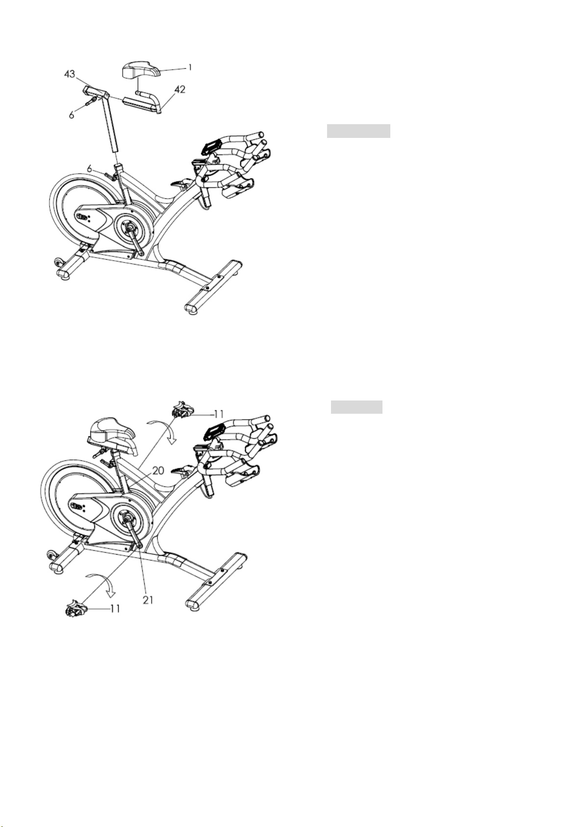
1 Saddle PC 35 Flywheel axle
SET
2 Alloy bind clamp ( L ) PC 36 Fixed wheel nut
3 Spring for release lever PC 37 Flywheel bearing
4 Alloy bind clamp ( R ) PR 15,15-1
15-2 Flywheel security washer & nut
5 Washer for release lever PC 63 Rubber cover for flywheel
6 Release lever PC 38 Axle bolt for moving wheel PC
7 Crank bolt PC 39 Moving wheel PC
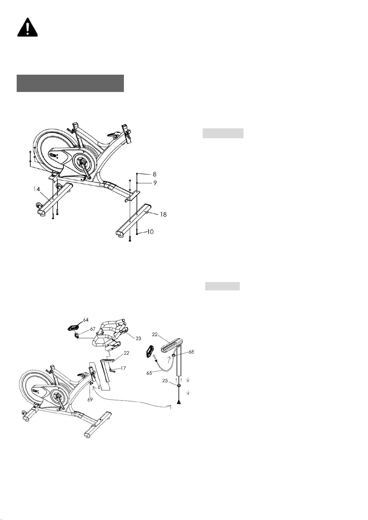
8 Foot tube nut PC 40 Plastic washer for release lever PC
9 Foot tube washer PC 41 Fixed bolt for release lever PC
10 Foot fixing bolt PC 42,29 Seat slider w/ end plug PC
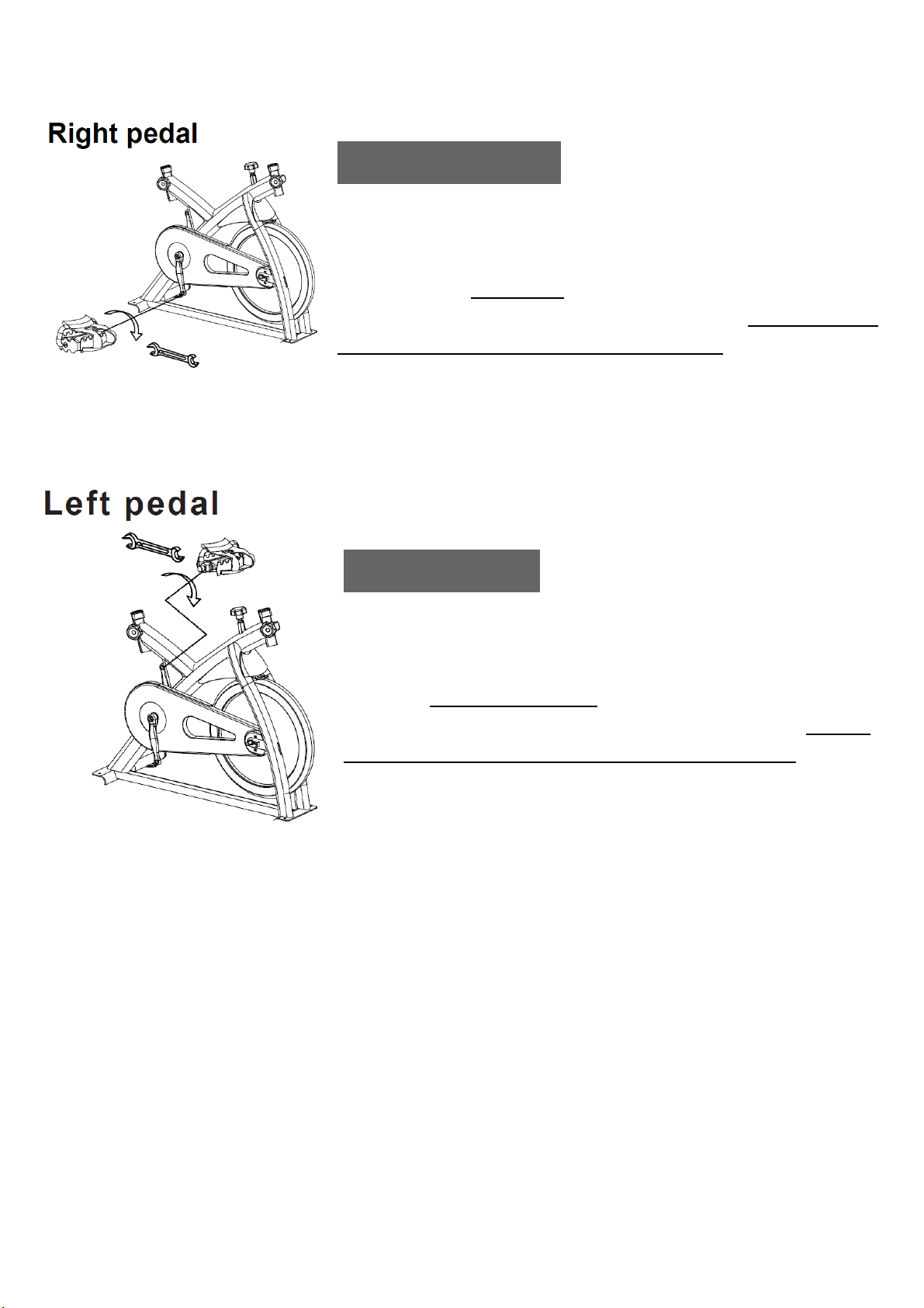
11 Pedal PR 43 Seat post PC
12 Front / Rear foot tube end cap PC 44 Washer for release lever PC
13 Foot tube adjuster pad PC 45 Belt PC
14 Rear foot tube Complete PC 47 Outer chain guard bolt M5 PC
16 Flywheel adjuster bolt PC 48 Bolt for protection tube PC
17 Handle bar release lever
w/washer PC 49 Flywheel (complete) SET
18 Front foot tube Complete PC 50 Rubber sleeves PC
19 Right belt guard PC 51 Fixed bolt for tension knob casing PC
20 Left crank arm PC 52 Idler w/bearing, clip SET
21 Right crank arm PC 53 Rubber sealed PC
22 Handle bar post PC 54 Handle for tension knob PC
23 Handle bar w/slider PC 55 Casing for tension knob PC
24 Tension knob set (complete) SET 56 Bolt for tension knob handle PC
25 End cap for handlebar post PC 58 Flywheel protection tube PC
27 Adjuster cable guide PC 61 Belt pulley with screw, magnet PC
28 Brake pad PC 63 Rubber cover for flywheel PC
29 End plug for seat slider PC 64 Console complete set SET
30 C Rubber sealed PC 65 Upper cable PC
31 Left belt guard PC 66 Sensor cable PC
32 Washer for protection tube PC 67 Clamp for console PC
33 BB bearing PC 68 Rubber eyelet PC
34 BB Axle with plate PC 69 Cable plug PC
36 Flywheel security nut PC G01 Magnetic brake set, brake pad SET
8

Saddle:
Make sure tighten enough for both side of nut after
adjust the saddle position. To prevent the saddle
from twisting side to side.
Instruction
It is important that the handlebar and seat are set at the correct height for your body. Ask your
instructor for assistance.
Emergency Brake:
Pushing the RED lever (54) of the Tension knob (24)
forward completely for emergency brake.
Handlebar adjustment - Adjusting the handlebar height-Undo
the adjuster release lever that is located at head tube (where the
handlebar post fits into the frame). Slide the handlebar post up or
down to the required height and retighten the adjuster release
lever. Make sure it is securely tightened and that there is no
lateral or vertical movement of the handlebar. The handlebar
position can also be adjusted forwards or backwards. Undo the
release lever located below the handlebar slider. Slide the
handlebar assembly forwards and backwards until you reach the
required position. Then securely re-tighten the release lever.
Pay attention on ”MIN INSERT” mark for safety adjustment.
Seat adjustment - Undo the adjuster release lever located at
seat tube (where the seat post fits into the frame). Adjust the seat
to the required height. Then retighten the adjuster release
lever. The seat position can be adjusted forwards and
backwards. Undo the adjuster release lever located directly
side of the seat slider. Loosen the adjuster release lever then
slide the seat to the required position. Then make sure the
adjuster release lever retighten.
Pay attention on ” MIN INSERT” mark for safety adjustment.
9

Maintenance Chart
No DESCRIPTION Daily Weekly Monthly Quarterly Annually
1
Keep machine clean: Wipe machine
down with clean & dry fabric to clear
dirt & sweat.
X
2 Wipe Anti-rusty cream or similar on
the seat post set, handlebar set X
3 Visual check X
4 Check security of handle bar post &
seat post X
5 Check security of saddle X
6 Remove handlebar post and clean
head tube X
7 Remove seat post and clean seat
tube X
8 Check if any noise X
9 Check tension knob system X
10 Check security of all knobs & release
leve
r
X
11 Check toe straps for signs of wear X
12 Check crank bolts and re-tighten X
13 Make sure pedals are screwed in X
14 Check the magnetic holder in correct
position X
15 Check belt tension X
16 Wipe the anti-rust oil on the middle
range of flywheel surface (avoid
the stickers) X
17 Check bottom bracket X
18 Check flywheel bearings X
19 Full service-frame inspection
※Adjusting the belt tension:
1) Loosen the bolt (47), and take off the belt guard (19, 31).
2) Loosen the nut (36).
3) Turn the nut of the adjuster bolt (16) to adjusting the belt tension. Suggest turn 1/4 circles each time.
Don't turn too much to causing tension too tight then damage the axle and bearings.
Please make sure this step be performed on both left & right sides and the adjustment distance is the
same. After adjusted, Make sure flywheel keeps parallel with frame and in the middle position.
4) After finished the above steps, screw the nut (36) by both sides. Make sure the nut is tighten and fixedly.
10

Computer Instructions
DISPLAY FUNCTION:
ITEM DESCRIPTION
SCAN
. In SCAN mode, press MODE/ENTER key to choose functions.
. Automatically scan through each mode in sequence every 6 seconds.
. The sequence of display when press MODE/ENTER key : TIME→
DIST→CAL→PULSE/LOAD→RPM/SPEED
SPEED
. Range 0.0 ~ 99.9
. Without any signal being transmitted into the monitor for 4 seconds
during workout, SPEED will display “0.0”
RPM
. Range 0 ~ 999
. Without any signal being transmitted into the monitor for 4 seconds
during workout, RPM will display “0”
TIME
. Without setting the target value, time will count up.
. When setting the target value, time will count down from your target time
to 0 and alarm will sound or flash.
. Without any signal being transmitted into the monitor for 4 seconds
during workout, time will STOP
. Ran
g
e 0:00 ~ 99:59
DISTANCE
. Without setting the target value, distance will count up.
. When setting the target value, distance will count down from your target
distance to 0 with an alarm sound or flash.
. Ran
g
e 0.00~99.99
CALORIES
. Without setting the target value, calorie will count up.
. When setting the target value, calories will count down from your target
calorie to 0 with an alarm sound or flash.
. Ran
g
e 0~9999
WATT . Display power consumption during workout.
.ran
g
e 0 ~ 999
LOAD .Display the level value when adjust LOAD.
. Range 1~16
PULSE
. Current pulse will display after 6 seconds when detected by the console.
. Without any pulse signal for 6 seconds, console will display “P”.
. Pulse alarm will sound when current pulse is over the target pulse.
. Ran
g
e 0-30~230 BPM
11

KEY FUNCTION:
OPERATION PROCEDURE
POWER ON
. LCD will display all segments as Drawing 1.
. Monitor working display as Drawing 2.
. When adjust LOAD, the monitor will display as Drawing 3.
Drawing1 Drawing2 Drawing3
POWER OFF
. Without any signal being transmitted into the monitor for 4 minutes the monitor will enter SLEEP
mode.
ITEM DESCRIPTION
SET
. Press SET key to increase value. Press and hold the key to increase value
faster.
. TIME setting range: 00:00~99:00 (Each increment is 1:00)
. CAL setting range: 0~9990 (Each increment is 10)
. DIST setting range: 0.00~99.50 (Each increment is 0.5)
. PULSE settin
g
ran
g
e:0-30~230
(
Each increment is 1BPM
)
MODE/ENTE
R
. Choose each function by pressing MODE/ENTER key.
. Press and hold MODE/ENTER key for 2 seconds to reset all functions (same
feature as the reset key if press for 2 seconds).
RESET . In setting mode, press RESET key once to reset the current function figures.
. Press RESET ke
y
and hold for 2 seconds to reset all function fi
g
ures.
RECOVERY . After the console detects pulse signal, press the RECOVERY key to enter
recovery mode to monitor heart rate recovery ability.
12

OPERATION
Workout setting
Press MODE/ENTER key to select the function of TIME, DISTANCE,CALORIES and PULSE.
Use SET Key for setting and press MODE key for confirmation.
For instance the time set-up, when the time value is blinking, you can use SET Key to adjust the
number. Press MODE/ENTER key for confirmation and skip to next set-up. The set-up of
DISTANCE/ CALORIES and PULSE is the same as TIME set-up.
Once the workout begins and the console picks up the exercise signal, the value of SPEED/RPM,
TIME, DST, CAL and PULSE will count up on the display.
Recovery
1. The RECOVERY key will only be valid if pulse is detected.
2. TIME will show "0:60" (seconds) and counts down to 0.
Computer will show F1 to F6 after the countdown to test heart rate recovery status. User can find
the heart rate recovery level based on the chart below.
3. Press RECOVERY key again to return to the beginning.
F1 Outstandin
g
F2 Excellent
F3 Good
F4 Fai
r
F5 Below avera
g
e
F6 Poo
r
Trouble shooting:
. When the display of LCD is dim, it means the batteries need to be changed.
. If there is no signal when you pedal, please check if the cable is well connected.
NOTE:
1. When stop training for 4 minutes, the main screen will be off.
2. If the computer displays abnormally, please re-install the batteries and try again.
APP
1. This console can connect APP on the smart device by Bluetooth.
2. Once console is connect to smart device via Bluetooth, the console will power off.
13

www.circlefitness.com
Sp8 Indoor Cycle
Always Moving Forward
Table of contents
Other CIRCLE FITNESS Exercise Bike manuals

CIRCLE FITNESS
CIRCLE FITNESS E7 User manual

CIRCLE FITNESS
CIRCLE FITNESS R6 User manual

CIRCLE FITNESS
CIRCLE FITNESS B-7 SERIES Quick start guide

CIRCLE FITNESS
CIRCLE FITNESS B8 E User manual

CIRCLE FITNESS
CIRCLE FITNESS R8 User manual

CIRCLE FITNESS
CIRCLE FITNESS R8 User manual

CIRCLE FITNESS
CIRCLE FITNESS E7 User manual

CIRCLE FITNESS
CIRCLE FITNESS Sp7 User manual

CIRCLE FITNESS
CIRCLE FITNESS E7 User manual