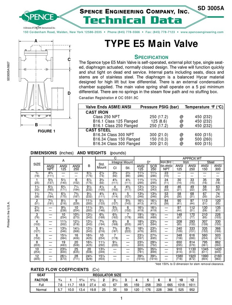
Circor Gyrolok User manual

Assembly Instructions
Use of a PST (Manual Pre Setting Tool) is recommended
GYROLOK®Marking Tool (GMT) is strongly recommended.
Fully insert a correctly cut, deburred
tube into the PST or fitting body
until the tube rests on the sizing
angle.
Holding the tube in the PST or
Body, extract the nut and
ferrules to visually ensure both
ferrules are correctly oriented.
Once correct ferrule orientation
is confirmed, thread & rotate the nut
onto the PST or Body until hand-
tight. The GMT witness line should
NOT be visible.
Establish a reference point for
wrench tightening by marking both
the fitting body and nut.
While supporting the PST or fitting
body, tighten the nut with a wrench
1¼ turns. The pre-set or make-up is
now complete. Confirm that the GMT
witness line is now visible.
(GMT Line)
(GMT Line)
GYROLOK®Marking Tool (GMT) is strongly recommended.
Ensure the HPST Tooling Set is installed with the proper indicator nut.
Insert the correctly cut and
deburred tube into the GMT as far
as possible.
Mark the tubing as shown with an
Ultra-Fine Point, Chloride-Free
pen (recommended Sharpie Model
37001). Take care to position the
marker perpendicular to the GMT, or
insufficient ferrule set could occur.
Fully insert a correctly cut,
deburred tube into the HPST
head. Visually ensure both ferrules
are correctly oriented. Thread &
rotate the nut until hand-tight.
Set the indicator arm in the
operating position by rotating the
Indicator Nut counter-clockwise
until it stops.
Pump the handle until the
indicator arm releases.
CAUTION: Stop pumping
immediately after the arm
releases, as over-pumping may
cause the tube to swell and stick.
Pre-setting is now complete.
Insert the end with pre-set ferrules
and nut into the fitting. Thread
and rotate the nut until hand-tight.
While supporting the fitting body,
tighten the nut with a wrench 1/2
turn for tubing up to 1” (25mm).
For tubing greater than 1” (25mm)
3/4 turn is required. The initial
fitting make-up is now complete.
Firmly insert end with the correctly
set ferrules & nut into the fitting.
Thread & rotate the nut until
hand-tight. The GMT witness line
should NOT be visible.
While supporting the fitting
body, tighten the nut with a
wrench ¼ turn.
Manual Assembly Instructions HPST Assembly Instructions
GYROLOK®MARKING TOOL (GMT) INSTRUCTIONS REMAKE INSTRUCTIONS
0-1/2” (12mm)
MANUAL ASSEMBLY
½” – 1” (12mm-25mm)
MANUAL OR HPST ASSEMBLY
based on installation conditions
Above 1” (25mm)
HPST ASSEMBLY REQUIRED
Consult factory as needed

1. Do not tighten or loosen any part of a fitting or valve when the system is pressurized. Make sure the system is un-pressurized when tightening or loosening a
fitting or valve connection.
2. Do not loosen GYROLOK®nut or any product component in order to relieve or bleed down system pressure.
3. Do not exceed pressure-temperature specifications stated in the appropriate catalog.
4. When the application involves use of a toxic or hazardous fluid, exercise extra caution during operation and maintenance.
5. Before assembling new, unused GYROLOK®tube fitting ends, loosen the GYROLOK®nut before inserting the tube to allow full insertion of the tube to the
base of the body bore.
6. Always use tubing that is compatible with the fitting or valve material. Tubing appropriate for use with HOKE®products is described in Tubing Data Charts.
For example, use 316 Stainless Steel fittings with 316 Stainless Steel tubing.
7. Always leave a length of straight tube between the tube bend and the fitting. A tube bent too close to the fitting connection may be a source of leakage.
8. During assembly of the GYROLOK®tube end, always hold the fitting or valve body with one wrench while separately wrench tightening the GYROLOK®nut.
Follow the same precaution when disassembling.
9. Always use a HOKE®tube insert (basic part number “TI”) when assembling a GYROLOK®fitting to soft, pilable plastic tubing.
10. Always use proper thread lubricants or sealants on tapered pipe threads. Note that thread sealants may have lower temperature ratings than the basic fitting.
11. When installing an NPT ended valve, hold the valve body near the connection with one wrench, while separately wrench tightening the mating pipe. Turn the
pipe, not the valve. Follow the same precaution when disconnecting.
12. Do not hold the valve handle when tightening an end connection.
13. Do not use excessive force to open or close a ball valve e.g. do not use a handle extension.
14. On initial installation, valves may require an adjustment of the packing nut due to storage variations, systems parameters, and cold flow properties of TFE.
PO Box 4866 • Spartanburg, SC 29305-4866 USA • 864.574.7966
www.HOKE.com
Safety Instructions
It is solely the responsibility of the system designer and user to select products suitable for their specific application requirements and to ensure
proper installation, operation and maintenance of these products. Material compatibility, product ratings, and application details should be considered
in the selection.
Always contact your local HOKE®Distributor with any questions you may have before pressurizing and operating the product.
Product information described herein is offered for use by the system designer and user.
!WARNING
Improper selection or use of products described herein can cause
Personal injury or property damage
We Care About Your Safety
!
59-650 • 11/18/15 • APS5857
PLUGS & PORT CONNECTORS TUBE ADAPTERS & REDUCERS
Remove and discard ferrules. Firmly insert
the plug or port connector into the end
connection and hand-tighten the nut.
While supporting the fitting body, tighten
the nut with a wrench ¼ turn.
For this type of fitting please
follow the Manual Assembly
Instructions.
SAFETY WARNING:
GYROLOK®products are designed for installation only by professional suitably qualified licensed system installers experienced in the applications and
environments for which the products are intended. These products are intended for integration into a system. Where these products are to be used
with flammable or hazardous media, precautions must be taken by the system designer and installer to ensure the safety of persons and property.
Flammable or hazardous media pose risks associated with fire or explosion, as well as burning, poisoning or other injury or death to persons and/
or destruction of property. The system designer and installer must provide for the capture and control of such substances from any vents in the
product(s). The system installer must not permit any leakage or uncontrolled escape of hazardous or flammable substances. The system operator
must be trained to follow appropriate precautions and must inspect and maintain the system and its components including the product(s) and at
regular intervals in accordance with timescales recommended by the supplier to prevent unacceptable wear or failure.
Table of contents
Other Circor Control Unit manuals
Popular Control Unit manuals by other brands

Pilz
Pilz PSEN cs 4.2p/M12 operating manual

Agilent Technologies
Agilent Technologies 8495D Operating and service manual

INIM
INIM Flex2R Installation and programming manual

Becker
Becker CentralControl CC41 Commissioning Instruction

Emerson
Emerson Fisher Multiport Flow Selector instruction manual

Dometic
Dometic MCS-CTRL Installation and operation manual