OACE3 0601.04 en-GB, ID-No.: 176-622/0
www.imo.se 7
Start-up
Before starting
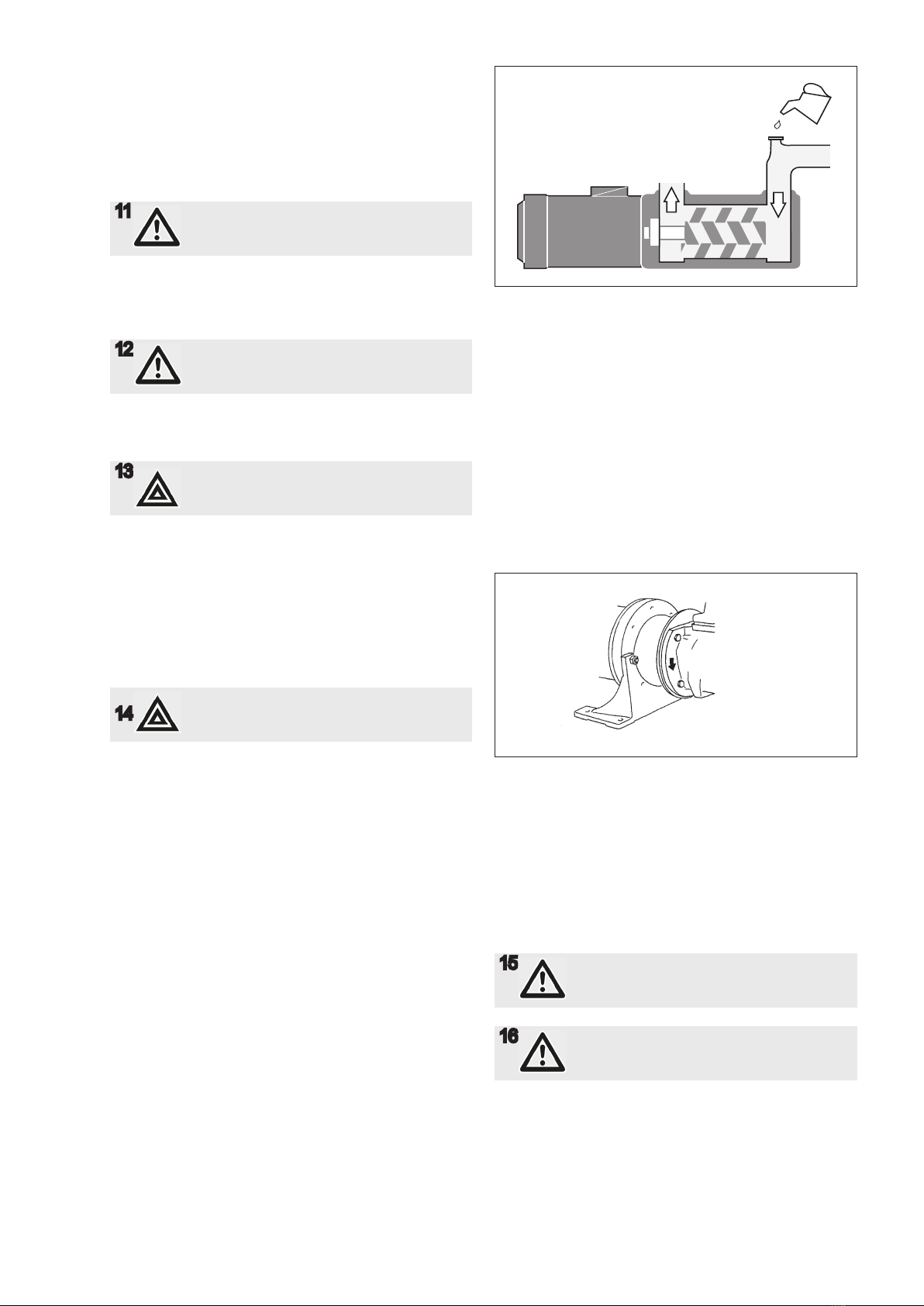
After installation and whenever it can be assumed that
the pump has been emptied, the pump must be thor-
oughly lled with liquid. See g 11.
11 Make sure the prime mover is locked out
and can not be started accidentally.
Rotate the shaft by hand while lling the pump, to
ensure that the rotor bores and magnetic couplings are
lled. This is done by rotating the fan on the electric mo-
tor after removing the fan cover.
12 Do not forget to t the motor fan cover
again before making start of motor
possible.
If the suction pipe cannot be completely lled, it is
important to ensure that the trapped air is evacuated
without any pressure build up. (See g. 5 Deaeration).
13 Starting a dry pump is likely to cause
damage to the pump and it's bearing and
magnetic coupling.
Direction of rotation
When the pump is ready to be started, switch the motor
briey on and off and check that the drive motor rotates
in the correct direction as indicated by the rotation ar-
row.
The arrow is placed on different spots depending on the
pump series.
14 Don't mix up with arrow for inlet and outlet!
Starting
Check that all valves necessary for the operation are
fully opened in both discharge and suction lines.
The rst time, the pump should be started with the ad-
justing spindle of the pressure relief valve tightened to
half of the available turns (the valve setting is increased
when the spindle is turned clockwise).
By monitoring the pressure gauge it can be determined
when the suction line is primed and the pump begins to
work. Should the pump not operate normally soon after
start, stop the pump within half a minute. Start again
after about 3-5 minutes and run for half a minute. This
procedure may need to be repeated a couple of times if
the suction line is long. Should the pump still not work, it
must be assumed there is a problem in the system that
needs to be remedied. Check the suction line calcula-
tion on page 4 and/or see ”Trouble shooting”, page 8.
Setting the pressure relief valve
The setting of the opening pressure is made as follows:
Tighten the valve spindle by rotating clockwise to the
maximum extent. The system pressure is regulated by
throttling to required value.
Fig. 11 Filling the pump
Fig. 13 Direction of rotation
The pressure relief valve is eased until the pressure is
just beginning to decrease by turning the spindle CCW.
The valve is now preset for desired opening pressure.
Open the throttling valve entirely.
15 If operating temperature exceeds 60°C
(149°F), appropriate measures to avoid
skin contact shall be provided.
16 Use hearing protections whenever high
noise can be expected from pump, motor
and/or environment.