Issue J Jun 03
PAGE
2
E1M18 and E2M18 Rotary Vacuum Pumps
INTRODUCTION
2
• When flammable or pyrophoric materials are
present within the equipment you must:
• Not allow air to enter the equipment.
• Ensure that the system is leak tight.
• Use an inert gas purge (for example, a
nitrogen purge) to dilute any flammable gases
or vapours entering the pump inlet, and/or
use an inert gas purge to reduce the
concentration of flammable gases or vapours
in the pump and in the exhaust pipeline to less
than one quarter of the gases' published lower
explosive limits (LEL).
• For further information, please contact BOC
Edwards: refer to the Addresses page at the end
of this manual for details of your nearest BOC
Edwards company.
1.3 Description
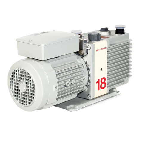
The BOC Edwards E1M18 and E2M18 pumps are
shown in Figure 1. Refer to Figure 1 for item
numbers in brackets in the following descriptions.
The E1M18 and E2M18 pumps are direct drive,
sliding vane pumps. The E1M18 is a single-stage
pump, and the E2M18 is a two-stage pump. The
pump is oil-sealed and designed for reliable, long-
term operation in both laboratory and industrial
environments. The pump is a free-standing unit. The
drive is provided through a flexible coupling by a
single-phase or three-phase (four pole) motor.
The motors are totally enclosed and are cooled by
the motor-cooling fan which directs air along the
motor fins.
The single-phase motors have a thermal overload
device. When the motor is too hot, the thermal
overload device switches off the pump. The thermal
overload device has an automatic reset; when the
motor cools down, the device resets and the motor
will restart. The single phase motors have an on/off
switch.
An oil pressure system lubricates the pump shaft
bearing surfaces and rotor sealing faces. The pump
has an oil distribution valve which prevents
discharge of oil to the pump interior (suckback)
after the pump stops. The pumping chambers are
air-tight, so this arrangement prevents air suckback
unless the gas-ballast valve is open. For protection in
this case, refer to Section 1.4.
You can inspect the level and condition of oil in the
oil box reservoir through the oil sight-glass (12). An
oil filler-plug (1) is fitted to the top of the oil box.
The pump has an oil drain-plug (11) to allow gravity
oil drain.
The pump has an inlet-port (6), outlet nozzle (2) and
gas-ballast control (3). The pump is mounted on an
aluminium alloy baseplate (10) on rubber pads.
Details of suitable vibration isolators and other
recommended accessories are given in Section 7.3.
1.4 Gas-ballast
When you use the pump with high vapour
throughputs, you should use the gas-ballast facility to
prevent condensation of the vapours inside the
pump. The condensates will contaminate the oil, will
cause performance to deteriorate and may cause
corrosion of the pump mechanism.
Air (or an inert gas) can be introduced into the
pump mechanism through the gas-ballast control
(Figure 1, item 3).
The gas-ballast control is a multi-turn valve:
• From the closed position, the first two turns
of the gas-ballast control provide an additional
oil-feed to the pump mechanism, but do not
introduce gas-ballast into the pump. The
additional oil-feed improves the lubrication
and sealing of the pump mechanism.
• With further turns of the gas-ballast control,
the gas-ballast flow into the pump increases
from zero flow, until the valve is fully open.

