manuals.online logo
Brands
  1. Home
  2. •
  3. Brands
  4. •
  5. Circuit-test
  6. •
  7. Multimeter
  8. •
  9. Circuit-test DCL-280 User manual

Circuit-test DCL-280 User manual

LIMITED WARRANTY
Circuit-Test Electronics warrants to the original purchaser that
this product be free of defect in material or workmanship for a
period of 2 years from the date of purchase. If this product
requires warranty service, return the unit (freight prepaid),
together with your dated proof of purchase and explanation of
the defect to:
In Canada: Circuit-Test Electronics
(Division of R.P. Electronic Components Ltd.)
2060 Rosser Avenue
Burnaby, BC, V5C 5Y1
Any product which has been subjected to misuse or accidental
damageisexcludedfromthewarranty.Exceptasstatedabove,
Circuit-TestElectronicsmakesnopromisesorwarrantieseither
expressed or implied including warranties of merchantability or
the fitness for any particular purpose. This warranty gives you
specific legal rights and you may have other rights which vary
under the laws of the various countries, states or provinces in
which Circuit-Test Electronics operates.
ACCESSORIES
Test Leads (set) TL-120
Hard Carrying Case (optional) CS-280
OWNER’S MANUAL
DIGITAL MULTIMETER
DCL-280
CIRCUIT-TEST
ELECTRONICS
INTRODUCTION
Your Circuit-Test DCL-280 Digital Clamp-on
Meterincorporatesthelatesttechnologytopro-
videyouwithafeature packed instrument. With
it you can measure a wide range of voltages,
current, resistance and frequency in the lab,
shop, car and home. This meter has been
designed for the Electrician, Technologist,
Hobbyist and Educational Institutions.
FEATURES
Frequency - display frequency to 20KHz
AC Current - measure to 600A AC
ContinuityBuzzer-easilycheckforcontinuity.
Diode Check - test diodes and other semicon-
ductors for open & short circuits.
Auto Power Shut-Off - meter automatically
shuts off 30 minutes after last operation
Overload Protection - protects the meter from
overvoltage and incorrect range selection
PRINTED IN TAIWAN
!
WARNING
1. Always start with the power off. Set the
range switch correctly before making any
measurements.
2. Do not operate the unit unless the case is
completely closed.
3. Disconnect test leads from equipment
before removing the battery or fuse.
4. Never connect unit to AC or DC powered
circuits when the range switch is set to
resistance,diodecheckorcontinuityranges.
5. To safeguard against electrical shock or
damage to instrument, never connect to
more than 600V DC or 600V AC between
input jacks and ground when measuring
low energy circuits or 250VAC / 250VDC
when measuring high energy circuits.
6. When using the test probes always keep
yourfingersbehindthefingerguardsonthe
probes.Nevertouchtheexposedprobetip.
7. Always inspect the instrument, test leads
and other accessories for damage prior to
use.
8. Disconnect the live / positive test lead prior
beforedisconnectingthecommon/negative
test lead.
9. Read this instruction manual carefully and
completely before using.
!
SAFETY PRECAUTIONS
Thismeterisnotrecommendedforhighvoltage
industrialuse;forexample,donotuseformeas-
urements on 440VAC or 600VAC industrial
power mains. The unit is intended for use with
lowenergycircuitsto600VDC/600VACorhigh
energy circuits to 250VAC / 250VDC only.
HighvoltageACandDCcircuitsaredangerous.
Use caution when working above 60VDC or
30VAC rms as these voltages pose a shock
hazard. Always consider circuits to be ener-
gized. Never assume any equipment is
de-energized. Lack of caution or poor safety
practices can be very dangerous and/or lethal.
SPECIAL FUNCTION
Max DataHold - WhenPEAK-Hispressed,the
last reading is held on the display.
the AC line being measured. Ensure that
the jaws are completely closed and not
making contact with the AC line. For
maximumaccuracyitisrecommendedthat
theconductorpassesthroughthecentreof
the clamp head opening.
3-4 ApplypowertotheAClinebeingmeasured.
3-5 Read the displayed current.
3-6 If the displayed current is less than 200A,
settherangeswitchtothenextlowerrange
position. For maximum accuracy select
the lowest range without overranging the
meter.
3-7 RemovepowertotheAClineandpressthe
trigger to open transformer jaws to remove
from the circuit.
4 RESISTANCE MEASUREMENT
!
WARNING: Remove all power from
circuit being tested when checking
resistance. Discharge any charged
capacitors.Neverconnecttheprobesto
any voltage while the selector is set to
Ω
OHM.
4-1 Plug the red test lead into the V
Ω
jack and
the black test lead into the COM jack.
4-2 Settherangeswitchtothedesired
Ω
setting.
4-3 Attach the test leads to the circuit.
4-4 Read the displayed resistance.
5 CONTINUITY TEST
!
WARNING: Remove all power from
circuit being tested when checking
continuity. Discharge any charged
capacitors.Neverconnecttheprobesto
any voltage while the selector is set to
2K .
5-1 Plug the red test lead into the V
Ω
jack and
the black test lead into the COM jack.
5-2 Set the range switch to the 2K setting.
5-3 Attach the test leads to the circuit.
5-4 The buzzer will sound when the circuit has
lessthan30Ωresistanceandthemeasured
resistance value will be displayed.
MEASUREMENTS
Pleasetakeafewminutestoreadtheseinstruc-
tions and warnings on both sides prior to use.
1 DC VOLTAGE MEASUREMENT
!
WARNING: Maximum input is 600V DC.
1-1 Plug the red test lead into the V
Ω
jack and
the black test lead into the COM jack.
1-2 Set the range switch to the desired DCV
setting.Itisbesttostartwiththe600Vrange
if the voltage is not known.
1-3 Apply the test leads to the circuit to be
measured. Ensure that the black lead is
connectedtothenegativesideofthecircuit
and the red lead to the positive.
1-4 Read the displayed voltage.
1-5 If the minus (-) sign appears the voltage is
negative at the point being measured.
2 AC VOLTAGE MEASUREMENT
!
WARNING: Maximum input is 600V AC
(RMS).
2-1 Plug the red test lead into the V
Ω
jack and
the black test lead into the COM jack.
2-2 Set the range switch to the desired ACV
setting.Itisbesttostartwiththe600Vrange
if the voltage is not known.
2-3 Apply the test leads to the circuit to be
measured.
2-4 Read the displayed voltage.
3 AC CURRENT MEASUREMENT
!
WARNING:Do not break or open the AC
line being measured. When measuring
ACcurrentthisunitisdesignedtoclamp
aroundoneofthe AC lines. Do not leave
clamped for more than 60 seconds. Do
not attempt to measure current using
the test leads.
3-1 Turn off power to AC line being measured.
3-2 Set the range switch to the 600A ACA
current setting.
3-3 Press the trigger to open clamp jaws and
close around one insulated conductor of
SPECIFICATIONS
GENERAL
Display: 3 1/2 digit, 13mm (0.5") H LCD
Maximum Display: 1999
Ranging: Manual ranging / Autoranging
on Frequency
Polarity: Automatic, minus (-) sign
indicates for negative polarity
Measuring Rate: 2.5 times/second
Input Impedance: 10 MΩ(DCV/ACV)
Operation Temp.: 0 to 45°C
Storage Temp.: -15 to 50°C
Power Source: 9V Battery, NEDA 1604 or
IEC 6F22
Dimensions: 82(W) x 192(H) x 33(D)mm
Weight: 270g (including battery)
RANGES AND ACCURACY
DC Voltage: 200V ±(2.5% + 1)
600V ±(4% + 1)
(Maximum measurement =
600V)
AC Voltage: 200V ±(1.5% + 4)
750V ±(3% + 4)
(Maximum measurement =
600Vrms)
(50 Hz - 500Hz)
AC Current: 200A 50/60 Hz ±(1.5% + 4)
40-500Hz ±(3.5% + 5)
20-600A 50/60 Hz ±(3.5%
+ 4)
40-500Hz ±(5.5% + 5)
Resistance: 2K-200KΩ±(1.5% + 1)
(Test voltage: 0.3VDC)
Frequency: 2K-20KHz ±(0.5% + 3)
(Maximum input = 500VDC /
ACrms/ Sensitivity: 80Vrms
minimum)
Diode : Test current: 1.0 ±0.6mA
Test voltage: 3V
OVERLOAD PROTECTION
Voltage: 600VDC / 600 VACrms
Current: 1000A AC for 60 seconds
Resistance: 500VDC / 500VACrms
Frequency: 500VDC / 500VACrms
Diode Test: 500VDC / 500VACrms
6 DIODE TEST
!
WARNING: Remove all power from
circuitbeingtestedwhenusingthediode
check.Dischargeanychargedcapacitors.
Neverconnecttheprobestoanyvoltage
while the selector is set to .
6-1 Plug the red test lead into the V
Ω
jack and
the black test lead into the COM jack.
6-2 Setthefunctionswitchtothe setting.
6-3 Connectthe probes to the device you want
to test. Note the meter reading.
6-4 Reverse the probes and note this reading.
6-5 Ifboth valuesare displaying .OLoverrange
the device is open. If both values are very
small the device is shorted. If one reading
indicates .OL overrange and the other
reading is small then the device is good.
7 FREQUENCY MEASUREMENT
!
WARNING: Maximum input is 500 V.
7-1 Plug the red test lead into the V
Ω
jack and
the black test lead into the COM jack.
7-2 Set the function switch to the Hz setting.
7-3 Connect the probes to the point of meas-
urement.
7-4 Read the displayed frequency.
8 BATTERY REPLACEMENT
!
WARNING: Disconnect both test leads
from any equipment before removing
back cover. Do not use meter with case
opened.
8-1 The “ ” will appear on the display when
the battery requires replacing.
8-2 Disconnect both test leads and turn off the
power.
8-3 Removethescrewinthesmallrearcoverof
the case and remove the cover.
8-4 Unsnapthebatteryfromtheconnectorand
replace with a new 9V battery.
8-5 Replace the cover and cover screw.
Other Circuit-test Multimeter manuals

Circuit-test DMR-1100 User manual

Circuit-test

Circuit-test DMR-1100 User manual

Circuit-test DCL-620 User manual

Circuit-test

Circuit-test DCL-620 User manual

Circuit-test DMR-2400 User manual

Circuit-test

Circuit-test DMR-2400 User manual

Circuit-test DMR-6700 User manual

Circuit-test

Circuit-test DMR-6700 User manual

Circuit-test DCL-420 User manual

Circuit-test

Circuit-test DCL-420 User manual

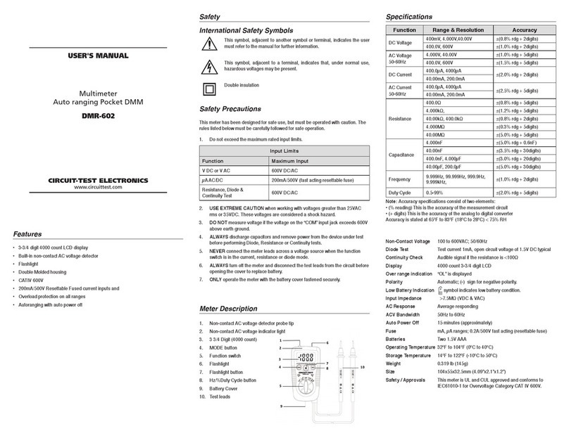
Circuit-test DMR-602 User manual

Circuit-test

Circuit-test DMR-602 User manual

Circuit-test DMR-1100A User manual

Circuit-test

Circuit-test DMR-1100A User manual

Circuit-test DMR-6500 User manual

Circuit-test

Circuit-test DMR-6500 User manual

Circuit-test DMR-4200 User manual

Circuit-test

Circuit-test DMR-4200 User manual

Circuit-test DMR-6550 User manual

Circuit-test

Circuit-test DMR-6550 User manual

Circuit-test DMR-6600 User manual

Circuit-test

Circuit-test DMR-6600 User manual

Circuit-test DMR-4350 User manual

Circuit-test

Circuit-test DMR-4350 User manual

Circuit-test DMR-1500 User manual

Circuit-test

Circuit-test DMR-1500 User manual

Circuit-test DMR-3600 User manual

Circuit-test

Circuit-test DMR-3600 User manual

Popular Multimeter manuals by other brands

C-LOGIC 5600 instruction manual

C-LOGIC

C-LOGIC 5600 instruction manual

SATA 03021 user manual

SATA

SATA 03021 user manual

Hioki DT4252 instruction manual

Hioki

Hioki DT4252 instruction manual

Amprobe AC71B user manual

Amprobe

Amprobe AC71B user manual

Extech Instruments 380947 user guide

Extech Instruments

Extech Instruments 380947 user guide

VOLTCRAFT VC5070 operating instructions

VOLTCRAFT

VOLTCRAFT VC5070 operating instructions

IDEAL ND 3511-1 instructions

IDEAL

IDEAL ND 3511-1 instructions

RS IDM 61 instruction manual

RS

RS IDM 61 instruction manual

Hongda USA DT95B instruction manual

Hongda USA

Hongda USA DT95B instruction manual

Good Will GDM-360 user manual

Good Will

Good Will GDM-360 user manual

Testboy TB 312 operating instructions

Testboy

Testboy TB 312 operating instructions

Phoenix Contact TESTFOX M operating manual

Phoenix Contact

Phoenix Contact TESTFOX M operating manual

Keysight U1233A user guide

Keysight

Keysight U1233A user guide

Duratool D03122 manual

Duratool

Duratool D03122 manual

TEXIO DL-1060 instruction manual

TEXIO

TEXIO DL-1060 instruction manual

Kewtech KT117 instruction manual

Kewtech

Kewtech KT117 instruction manual

Velleman DVM890 user manual

Velleman

Velleman DVM890 user manual

Keithley 2010 user manual

Keithley

Keithley 2010 user manual

manuals.online logo
manuals.online logoBrands
  • About & Mission
  • Contact us
  • Privacy Policy
  • Terms and Conditions

Copyright 2025 Manuals.Online. All Rights Reserved.