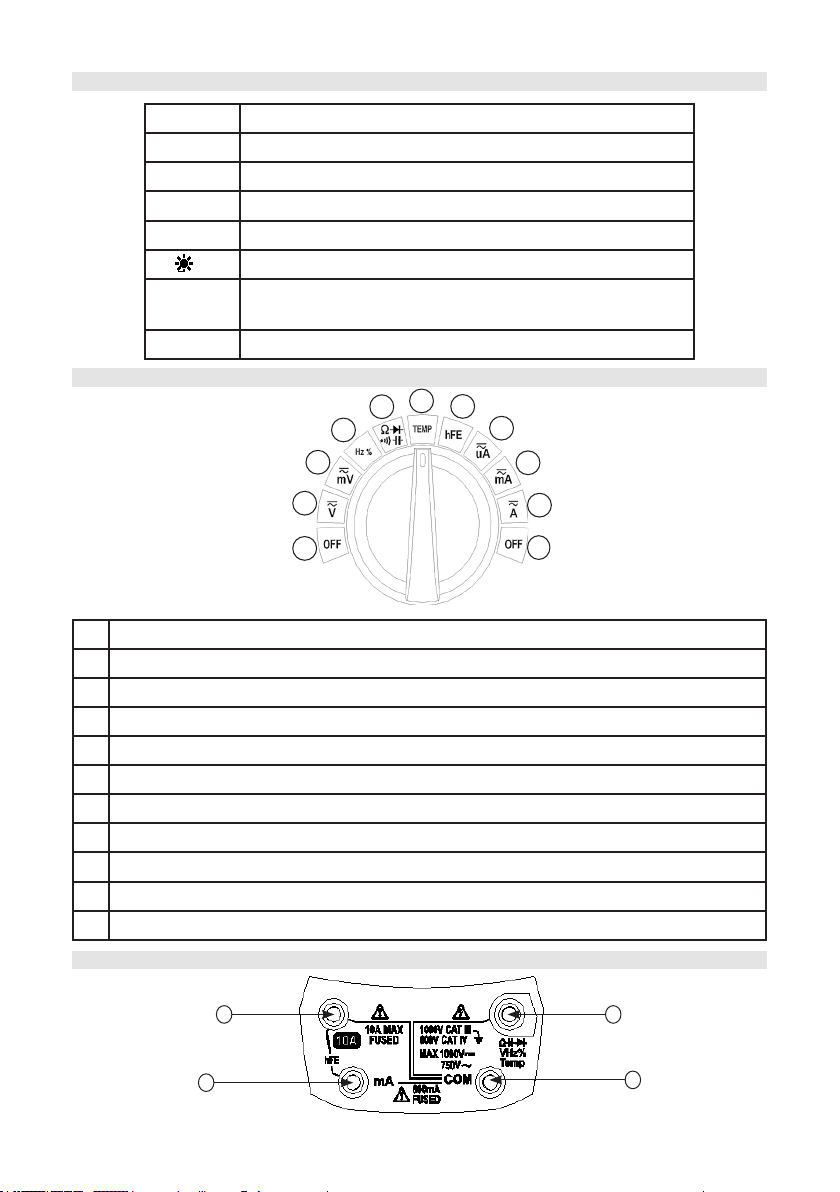
Duratool D03122 User manual

1
MODEL: D03122
DIGITAL MULTIMETER
WITH T-RMS/USB

2
CONTENTS
Page number Details
3 Important Safety Information
4 Safety Symbols
4 Display
5 Buttons
5 Rotary Switch
5 Input Socket
6 Measurement Operation
7 Measure AC & DC Voltage
8 Measure DC or AC mV Voltage
8 Measure Frequency & Duty Ratio
9 Measure AC or DC Current
9 Measure Resistance
10 Measure Connectivity
10 Measure Capacitance
10 Measure Diode
11 Measure Temperature
11 Measure Transistor
11 Auto Power-Off Function
12 Backlight Function
12 Data Hold
12 General Technical Specications
13 Accuracy Specication
13 DC Voltage
13 AC Voltage
13 DC Current
14 AC Current
14 Resistance
14 Capacitance
15 Frequency & Duty Ratio
15 Temperature
15 Diode Test
16 Connectivity Test
16 Cleaning & Maintenance
16 Replacing the Battery & Fuse

3
IMPORTANT SAFETY INFORMATION
Please read these instructions carefully before use and retain for future
reference.
• When using electrical appliances basic safety precautions should always be
followed.
• Use the meter only as specied in this manual, or the protection provided may be
impaired.
• Before using the meter, check the insulation around the input terminals of the
instrument. Do not use if any damage is present.
• Do not operate the meter, or use the probes, if they appear damaged, or if the
meter is not operating properly.
• There are no user-serviceable parts in this product. Refer servicing to qualied
personnel.
• Verify the meter’s operation by measuring a known voltage.
• Do not apply more than the rated voltage as marked on the meter, between the
terminals or between any terminal and earth ground.
• Use caution with voltages above 30V AC true RMS, 42V AC or 60V DC. These
voltages pose a shock hazard.
• Do not use the meter around explosive gas or vapour.
• When using the test leads, keep your ngers behind the nger guards of the
probe.
• Comply with local and national safety code. Wear personal protection equipment
(such as rubber gloves, masks and ame retardant clothes etc.) to prevent being
injured by electric shock due to exposed hazardous live conductors.
• When measuring, connect the zero line or the ground line rst, then connect the
live wire. When disconnecting, ensure that you disconnect the live wire rst and
then disconnect the zero line and ground line.
• Remove any probes from the meter before opening the meter case or battery door.
• Never operate the meter with the cover removed or the battery door open.
• Use only the test leads supplied or the protection may be impaired.
• Do not connect the meter to any voltage source while the rotary selector is in the
current, resistance, capacitance, diode or continuity range.
• If the probe is damaged, replace it with the same model number and same
electrical specications.
• Only use the batteries recommended for this product.
• Ensure that the batteries are inserted correctly, observing the plus and minus
marks on both the batteries and the compartment.
• Replace the batteries as soon as the low battery indicator appears on the display.
• Fit a full set of batteries at one time.
• Remove dead batteries from the appliance or if it is not going to be used for a long
time.
• Never mix old and new batteries together, or different types of batteries.
• Never dispose of batteries in a re, or attempt to recharge ordinary batteries.

4
SAFETY SYMBOLS
Symbol Description
High Voltage Warning
AC (Alternating Current)
DC (Direct Current)
AC or DC
Warning - Important Safety Information
Ground
Fuse
Double Insulation
Low Battery
CAT. III 1000V CAT. III 1000V over-voltage protection
CAT. IV 600V CAT. IV 600V over-voltage protection
DISPLAY
1
2
3
4
5
6
7
89
10
11
12
13
14
151617
18
19
20
1Auto-power off 8DC indicator 15 Max/Min Value
Measurement
2Simulation bar, indicating
rapid change trend
9Resistance/
Frequency Unit
16 USB Interface Open
3Battery undervoltage
indicator
10 Voltage/Current
Unit
17 Data Display Area
4Connectivity
Measurement Indicator
11 Capacitance Unit 18 Relative Value
Measurement
5Diode Measurement 12 Temperature Unit 19 Data Hold
6Minus 13 Transistor Indicator 20 Automatic Range
7AC indicator 14 Duty Ratio Unit

5
BUTTONS
Button Details
RANGE Switch between automatic range and manual range
Hz% Switch between frequencey and duty ratio
REL/USB Turn on relative measurement and USB
°C/°F Switch between celsius and fahrenheit
/H Turn on the backlight and data hold
MAX/MIN Turn on maximum value, minimum value, maximum-
minimum measurement
FUNC. Switch among function selections.
1 OFF
2 AC or DC Voltage. Press “Func.” to switch
3 AC or DC Voltage mV. Press “Func.” to switch
4Frequency, duty ratio. Press “Hz%” to switch
5Resistance, diode, connectivity, capacitance. Press “Func.” to switch
6 Temperature measurement. Press “°C/°F” to switch
7Transistor amplication test
8 AC and DC current microampere measurement. Press “Func.” to switch
9 AC and DC current milliampere measurement. Press “Func.” to switch
10 AC and DC current ampere measurement. Press Func. to switch
11 Off
1
2
3
4
567
8
9
10
11
ROTARY SWITCH
INPUT SOCKET
1
23
4

6
1
Used for AC and DC current measurement (maximum 10A), input socket for
frequency/duty ratio measurement (frequency measurement in current mode);
when testing transistor, multi function test socken “IN” input socket.
2
Used for AC and DC microampere (µA) and milliampere (mA) measurement
(maximum 600mA) and input socket for frequency/duty ratio (frequency
measurement in current mode); when testing transistor, multi-function test
socket “COM” input socket.
3Used as common terminal for all measurement; negative input socket of K-type
thermocouple temperature measurement.
4
Input socket for voltage, resistance, connectivity, diode, capacitance, frequency,
duty ratio measurement; positive input socket of K-type thermocouple
temperature measurement.
MEASUREMENT OPERATION
Manual and Automatic Range
• In auto ranging mode, the instrument will select the best range for the input signal
to be detected. The user does not need to select a range when changing the
measured signal.
• The instrument can also be set to manual ranging.
• The default mode, when the instrument is turned on or after the function is
changed, is automatic range. The instrument displays the “AUTO” symbol.
To enter or exit manual ranging, perform the following steps:
• In automatic ranging mode, press the RANGE button, the “AUTO” symbol will
disappear from the display.
• Press the RANGE button to increase the range. When the maximum range is
reached, the instrument will return to the minimum range.
• Press and hold the RANGE button for two seconds to exit manual ranging mode.
The instrument will display the “AUTO” symbol.
Note: Duty ratio, connectivity, diode, temperature and transistor measurement functions
only have a single range.
Relative Value Measurement
The instrument is equipped with relative value measurement function. In this mode, the
instrument display value = actual value - set reference value. Operations of entering or
quitting relative measurement are as follows:
• Set the instrument to the measurement function you need, connect the probes
with a source of value which you wish to set as reference value, the instrument will
display the measured value.
• Press REL/USB button and store the measured value as reference value, enter
the relative measurement mode and the instrument will display the “REL” symbol.
• Measure, and the instrument will display “actual value-set reference value”.
• Then press REL/USB button and exit relative value measurement mode, the “REL”
symbol will disappear from the display.
Note: frequency, duty ratio, diode, connectivity, temperature and transistor
measurement has no relative value measurement mode.

7
Maximum Value/Minimum Value/Maximum-Minimum Value Hold
The instrument is equipped with maximum value, minimum value and maximum-
minimum value hold function. The steps of entering or exiting this function are as
follows:
• Set the instrument to the measurement function you require.
• Press the MAX/MIN button to enter maximum value hold mode, the instrument will
display the “MAX” symbol.
• Press the MAX/MIN button again to enter minimum value hold mode, the
instrument will display the “MIN” symbol.
• Press the MAX/MIN button again to enter maximum-minimum value hold mode,
the instrument will display the “MAX-MIN” symbol.
• Press and hold the MAX/MIN button longer than 2 seconds to return the
instrument to the normal measurement mode.
Note: Frequency, duty ratio, diode, connectivity and transistor measurement do not
have this function.
USB Interface Function
The instrument is equipped with a USB interface function, measured data can be
uploaded to a computer for display, record and analysis via the USB port. The steps of
entering or exiting this function are as follows:
• Turn the rotary switch of the instrument to any position except “OFF”.
• Press and hold the REL/USB button for more than 2 seconds and the instrument
will display the “USB” symbol to show that the data transmission function is
enabled.
• Press and hold the REL/USB button again for more than 2 seconds, the “USB”
symbol will disappear to show that the data transmission function has been
disabled.
Note: please refer to the interface software operation instructions for detailed
operations.
MEASURE AC & DC VOLTAGE
• Turn the rotary knob to “Ṽ”, and press FUNC button and switch
between AC or DC voltage function.
• Insert the red probe into the “ ” socket, and the black probe into
the “COM” socket.
• Contact the probe to the measured circuit (connect to the circuit
under test in parallel) and measure the voltage.
• Read the measurement result on the screen.
• Note: In the AC voltage function, press the Hz% button to measure the frequency
and duty ratio of the AC voltage source, please refer to ‘Measure Frequency’ for
details.
• The AC voltage value measured by using this instrument is true RMS (root mean
square). For sine wave and other wave (no DC offset), such as square wave,
triangle wave and step wave, these measurements are accurate.
V
¡£¡£
V
WARNING
• Do not allow measurement of any voltage higher than DC 1000V or AC 750V
RMS, otherwise it may cause damage to the instrument, electric shock or
personal injuries.

8
MEASURE DC or AC mV VOLTAGE
• Turn the rotary knob to “mṼ, press the FUNC button and switch to
DC or AC voltage function.
• Insert the red probe into the “ ” socket and the black probe into
the “COM” socket.
• Connect the probe to the measured circuit (connect to the circuit
under test in parallel).
• Read the measurement result on the screen.
• Note: In AC voltage function, press the Hz% button to measure
the frequency and duty ratio of the AC voltage source. Please refer to ‘Measure
Frequency’ for details.
• The AC voltage value measured by using this instrument is true RMS (root mean
square). For sine wave and other waves (no DC offset), such as square wave,
triangle wave and step wave, these measurements are accurate.
• The maximum range for AC/DC mV (60/600mV) voltage measurement is 600mV,
the input impedance is up to 10 Ω and any measurement of weak signals should
not be attenuated.
V
¡£¡£
V
11
WARNING
• Do not allow measurement of any voltage higher than DC 1000V or AC 750V
RMS, otherwise it may cause damage to the instrument, electric shock or
personal injuries.
• Do not apply voltage exceeding DC 1000V or AC 750V RMS between the
common terminal and the earth, otherwise it may cause damage to the
instrument, electric shock or personal injuries.
MEASURE FREQUENCY & DUTY RATIO
• Turn the rotary knob to “Hz%”, press the Hz% button and switch
between frequency and duty ratio (in AC voltage or AC current
shift frequency and duty ratio can also be measured)
• Insert the red probe in “ ” socket and the black probe in “COM”
socket.
• Connect the probe to the measured circuit (connect to the circuit
under test in parallel), measure the frequency or duty ratio.
• Read the measurement result on the screen.
Hz
¡£
¡£
WARNING
• Do not allow measurement of any voltage higher than DC 1000V or AC 750V
RMS, otherwise it may cause damage to the instrument, electric shock or
personal injuries.
• Do not apply voltage exceeding DC 1000V or AC 750V RMS between the
common terminal and the earth, otherwise it may cause damage to the
instrument, electric shock or personal injuries.
WARNING
• Do not apply voltage exceeding DC 1000V or AC 750V RMS between the
common terminal and the earth, otherwise it may cause damage to the
instrument, electric shocks or personal injuries.

9
MEASURE AC OR DC CURRENT
• According to the current of measurement turn the rotary knob to any position
among “ ”, “ ” and “ ”, press the “FUNC.” button and switch between the AC or
DC functions.
• According to the position of measurement insert the red probe into the “mA” socket
or “10A” socket, and the black probe in the “COM” socket.
• Disconnect the power supply of the measured circuit, connect the probe to the
circuit under test in series, and turn on the power supply of the circuit.
• Read the measurement result on the screen.
V
V
¡£
¡£
V
V
¡£
¡£
V
V
¡£¡£
WARNING
• Do not allow measurement of any voltage higher than DC 1000V or AC 750V
RMS, otherwise it may cause damage to the instrument, electric shock or
personal injuries. The pwoer supply of the measured circuit must be switched off
rst, otherwise it may cause an electric shock or personal injuries.
• To avoid any damage to the instrument or equipment, please check the fuse
before measurement and use the correct input socket.
MEASURE RESISTANCE
• Scroll the rotary knob to “ ”, press the “FUNC.” button and switch
to resistance measurement function and ensure the power supply
of the measured circuit has been cut off.
• Insert the red probe in “ ” socket, and the black probe in “COM”
socket.
• Contact the probe to the measured circuit or both ends of the
resistor.
• Read the measurement result on the screen.
¡£¡£
WARNING
• To avoid any damage to the instrument or equipment, do not input frequency or
duty ratio signal higher than 10V RMS.
WARNING
• Before measuring resistance, connectivity, capacitance or diode, please turn off
the power supply and discharge all the high voltage capacitors, otherwise it may
cause damage to the instrument, electric shock or personal injuries.
• Note: Because the test current of the instrument will pass through all the routes
between the probe, the measured value of the resistors in the circuit is usually
different from the rating of the resistor.

10
MEASURE CONNECTIVITY
• Scroll the rotary knob to “ ”, press the “FUNC.” button and switch
to connectivity measurement function, and ensure that the power
supply of the measured circuit has been cut off.
• Insert the red probe into the “ ” socket, and the black probe into
the “COM” socket.
• Contact the probe to the measured circuit or both ends of the
resistance.
• If the resistance of the measured resistance or circuit is lower than
50Ω, the buzzer will sound.
• At the same time the resistance of the measured circuit is displayed on the screen.
¡£¡£
WARNING
• Before measuring resistance, connectivity, capacitance or diode, please turn off
the power supply and discharge all the high voltage capacitors, otherwise it may
cause damage to the instrument, electric shock or personal injuries.
MEASURE CAPACITANCE
• Scroll the rotary knob to the “ ” position, press “FUNC.” button and
switch to capacitance measurement function.
• Insert the red probe into the “ ” socket, and the black probe into the
“COM” socket.
• Contact the probe to both ends of the capacitor.
• After the reading is stable, read the measurement result on the
screen.
¡£¡£
WARNING
• Before measuring resistance, connectivity, capacitance or diode, please turn off
the power supply and discharge all the high voltage capacitors, otherwise it may
cause damage to the instrument, electric shock or personal injuries.
MEASURE DIODE
• Turn the rotary knob to the “ ” function, press “FUNC.” button and
switch to diode measurement function.
• Insert the red probe into “ ” socket, and the black probe into the
“COM” socket.
• Contact the red probe to the anode of the measured diode, and the
black probe to the cathode of the measured diode.
• Read the measurement results on the screen.
• If the polarity of the probe and the diode are opposite, the instrument will display
“OL”, which can be used to differentiate the anode and cathode of the diode.
¡£¡£
WARNING
• Before measuring resistance, connectivity, capacitance or diode, please turn off
the power supply and discharge all the high voltage capacitors, otherwise it may
cause damage to the instrument, electric shock or personal injuries.
Note: The instrument can display values as high as 1.5V forward bias. A typical diode
forward bias is in the range from 0.3V to 0.8V. However, readings may be different due
to the different resistances of other circuits between the probes.

11
MEASURE TEMPERATURE
• Turn the rotary knob to “TEMP”.
• Insert the K-type thermocouple into the input socket of the instrument, with the
positive end of the thermocouple (red) in the “ ” socket, and the negative end
(black) in the “COM” socket.
• Contact the probe of the thermocouple to the measured object and read the result
from the main display area on the screen.
• Press the “°C/°F” button to switch between celsius and fahrenheit unit.
• Note: When the thermocouple is not inserted it will display the temperature of the
environment.
• The instrument is not suitable for measuring the temperature of a rapidly changing
environment.
• The cold junction compensation of the thermocouple is set in the instrument,
and it takes a longer time to reach thermal balance with the environmental
measurements. When measuring without the thermocouple, the instrument
requires an adjustment period in the environment to obtain accurate readings.
• The instrument uses K-type thermocouple probe.
WARNING
• When measuring temperature by thermocouple, the probe of the thermocouple
cannot contact the charged object, otherwise it may cause the instrument
damage, electric shock or personal injuries.
• Caution: Do not fold the thermocouple wire into an acute angle. Repeatedly
bending the wire over a period of time may cause the wire to break.
MEASURE TRANSISTOR
• Turn the rotary knob to “hFE”.
• Insert the multi-functional test socket in “10A” and “mA” sockets as
shown in the gure on the right.
• Insert the transistor in the corresponding socket of the multi-functional
test socket.
• Read the measurement results on the screen.
• Use caution when using the multi-functional, pay attention to the
direction of the insertion; if it is reversed the test result will be wrong.
WARNING
• Do not use the multi-functional test socket in voltage and current measurement,
otherwise it may cause damage to the instrument, electric shock or personal
injuries.
AUTO POWER-OFF FUNCTION
• If there’s no operation for 15 minutes while the unit is turned on, the instrument will
enter ‘Sleep’ mode, meaning it will power off automatically to save battery power.
• After entering sleep mode, the instrument will turn on if the rotary switch or any
buttons are pressed.
• If the “FUNC.” button is pressed to turn on the unit, it will cancel the auto power-off
function.
• Note: When USB function is enabled, the instrument will not enter the sleep state.

12
BACKLIGHT FUNCTION
• The instrument is equipped with a backlight function to enable accurate reading of
measurement results in places with bad light. Operations of turning on or off the
backlight are as follows:
• Press and hold the “ ” button for more than 2 seconds to turn on the backlight.
• Press and hold the “ ” button for more than 2 seconds again to turn off the
backlight; or after about 15 seconds the backlight will turn off automatically.
• Note: Frequent use of the backlight will shorten battery life.
• When the battery voltage is less than 4.8V, the display will show “ ” (low
battery) symbol. When using the backlight because of the increased current
draw, the battery voltage may drop below 4.8V and cause the “ ” symbol to be
displayed (when “ ” symbol displays, the accuracy of the measurement cannot
be guaranteed). At this time simply discontinue using the backlight. When the
“ ” symbol is displayed without the use of the backlight, then replace the battery
immediately.
DATA HOLD
• In the process of measurement, if a held reading is required, press the “ ” button,
the displayed value on the screen will be held.
• Press the “ ” button again to clear hold mode.
GENERAL TECHNICAL SPECIFICATIONS
Environmental Conditions 600V CATIV and 1000V CATIII
Pollution Level 2
Altitude <2000m
Working Environment
Temperature and Humidity 0 to 40°C (<80% RH, <10°C non-condensing)
Storage Environment
Temperature and Humidity -10 to 60°C (<70% RH, remove the battery)
Temperature Coefcient 0.1 x accuracy/°C (<18°C or >28°C)
Max. Voltage Between
Terminals Earth and Ground 1000V DC or 750V AC RMS
Fuse Protection mA: fuse F600mA/1000V fast speed fuse;
10A shift: F10A/1000V fast speed fuse
Sampling Rate About 3 times/second
Display
6000 counter readout. Automatically display the unit
symbols according to the shift of the measurement
function
Over Range Indication The screen displays “OL”
Low Battery Indication When battery voltage is lower than the normal
working voltage, “ ” will be displayed
Input Polarity Indication Automatically displays “ ”

13
ACCURACY SPECIFICATION
The accuracy applies within one year after the calibration.
Reference condition: the environment temperature 18°C to 28°C, the relative humidity
is no more than 80%, accuracy: ±(% reading + word).
DC VOLTAGE
Range Resolution Accuracy
Input impedance: 10MΩ(60/600mV
range is 10 Ω)
Overload protection: 1000V DC or 750V
AC (RMS)
Maximum input voltage: 1000V DC
60mV 0.01mV
±(0.7% reading + 2)
600mV 0.1mV
6V 1mV
60V 10mV
600V 100mV
1000V 1V
11
Note: Measure in mV (60/600mV) voltage, input impedance is as high as 10 Ω, and a
weak signal of measurement does not weaken, so the measurement precision is high.
But in the circumstance that the probe is open circuit, it will display numbers, which is
normal, as long as in short circuit the probe will return to zero or if the probe is inserted
to the measured point, the reading will stabilize.
11
Power Requirement 4 x 1.5V AA batteries
Dimensions 204x94x57mm (LxWxH)
Weight About 410g (inluding batteries)
AC VOLTAGE
Range Resolution Accuracy Input impedance: 10MΩ(60/600mV
range is 10 Ω)
Overload protection: 1000V DC or 750V
AC (RMS)
Maximum input voltage: 750V AC
(RMS)
Frequency range: 10Hz ~ 1kHz;
response: true RMS
60mV 0.01mV
±(0.8% reading + 3)
600mV 0.1mV
6V 1mV
60V 10mV
600V 100mV
750V 1V ±(1.0% reading + 3)
11
Note: Measure in mV (60/600mV) voltage, input impedance is as high as 10 Ω, and a
weak signal of measurement does not weaken, so the measurement precision is high.
But in the circumstance that the probe is open circuit, it will display numbers, which is
normal, as long as in short circuit the probe will return to zero or if the probe is inserted
to the measured point, the reading will stabilize.
11
DC CURRENT
Range Resolution Accuracy Overload protection: µA/mA range:
600mA/1000V fuse (fast speed fuse)
10A range: 10A/1000V fuse (fast speed
600µA 0.1µA ±(1.2% reading + 3)
6000µA 1µA

14
• When measuring large current, continuous measurement should not be longer
than 15 seconds.
• After measurement, the instrument should be cooled down after twice of the
measurement time and then enter the small current measurement.
AC CURRENT
Range Resolution Accuracy Overload protection: µA/mA range:
600mA/1000V fuse (fast speed fuse)
10A range: 10A/1000V fuse (fast
speed fuse)
Maximum input current:
- mA socket: 600mA
- 10A socket: 10A
Frequency range: 10Hz ~ 1kHz
Response: true RMS
600µA 0.1µA
±(1.5% reading + 3)
6000µA 1µA
60mA 10µA
600mA 100µA
6A 1mA ±(3.0% reading + 10)
10A 10mA
• When measuring large current, continuous measurement should be no longer than
15 seconds, after measurement the instrument should be cooled down after twice
of the measurement time, then enter small current measurement.
RESISTANCE
Range Resolution Accuracy
Open circuit voltage: about 0.25V
Overload protection: 1000V DC or 750V
AC (RMS)
600Ω 0.1Ω
±(1.2% reading + 5)
6kΩ 1Ω
60kΩ 10Ω
600kΩ 100Ω
6MΩ 1kΩ
60MΩ 10kΩ ±(2.0% reading + 5)
CAPACITANCE
Range Resolution Accuracy Overload protection: 1000V DC or
750V AC (RMS)
Note: Parameter does not include
erros cause by the capacitor and
capacitor substrate of the probe (in
100nF range may be to a few nF).
The user can use the relative value
measurement function to reduce the
error.
10nF 0.001nF
±(3.0% reading + 3)
100nF 0.01nF
1000nF 0.1nF
10µF 0.001µF
100µF 0.01µF
1000µF 0.1µF
10mF 0.001mF
Range Resolution Accuracy fuse)
Maximum input current:
- mA socket: 600mA
- 10A socket: 10A
60mA 10µA ±(1.2% reading + 3)
600mA 100µA
6A 1mA ±(2.0% reading + 10)
10A 10mA

15
FREQUENCY & DUTY RATIO
Range Resolution Accuracy • Through shift of Hz:
• Measurement range: 0 ~ 10MHz.
• Input voltage range: 0.2~10V AC ( the
input voltage should be increased with the
increase of the measured frequency) .
• Overload protection: 1000V DC or 750V AC
(RMS).
• Through shift V:
• Measurement range:0 ~ 100kHz.
• Input voltage range: 0.5~750V AC ( the
input voltage should be increased with the
increase of the measured frequency).
• Maximum input voltage: 1000V DC or 750V
AC (RMS).
10Hz 0.001nF
±(1.0%
reading
+ 5)
100Hz 0.01nF
1000Hz 0.1nF
10kHz 0.001µF
100kHz 0.01µF
1MHz 0.1µF
10MHz 0.001mF
1~99% 0.1% ±3.0%
• Through shifts of µA, mA, A:
• Measurement range:0 ~ 100kHz.
• Input signal range: ≥ ¼ range ( the input current should be increased with the
increase of the measured frequency).
• Input protection: µA, mA range: F600mA/1000V ultra-speed fuse; 10A range:
F10A/1000V ultra-speed fuse.
• Note: Compared with the range of measurement by using the “Hz” function of
voltage and current shifts, using shift “Hz” to measure the frequency has a larger
range and higher sensitivity.
DIODE TEST
Range Resolution Accuracy • Forward DC current is about 1mA
• Reverse DC voltage is about 1.5V
• Overload protection: 1000V DC or
750AC (RMS).
1mV
Displays the approx.
forward voltage value
of the diode.
TEMPERATURE
Range Resolution Accuracy
• Overload
protection:
1000V DC
or 750V AC
(RMS)
°C 1°C
-20 to 0°C ± 5.0% reading or ± 3°C
0 to 400°C ± 1.0% reading or ± 2°C
400 to 1000°C ± 2.0% reading
°F 1°F
-4 to 32°F ± 5.0% reading or ± 6°F
32 to 752°F ± 1.0% reading or ± 4°F
752 to 1832°F ± 2.0% reading

16
• The above accuracy specications are specied in the same operating
environment after keeping the instrument in a xed state for at least one hour.
• If the instrument is exposed to an environment of high humidity during a period of
storage, ensure that the instrument be kept in the same operating environment for
at least two hours.
• Accuracy does not contain the tolerance of the thermocouple probe.
CLEANING & MAINTENANCE
• If there is dust on the terminal or the terminal is wet, it may cause measurement
error.
• Switch off the power supply of the instrument and remove the test probes.
• Turn over the instrument and shake out the dust accumulated in the input socket.
• Wipe the outer cabinet with a damp cloth and a mild detergent.
• Do not use any chemicals, abrasives or solvents that may damage the instrument.
• Wipe the contacts in each input socket with a clean cotton swab soaked in alcohol.
REPLACING THE BATTERY AND FUSE
Battery
• Turn off the power supply of the instrument, and remove the probe on the
instrument.
• Unscrew the two screws xing the battery cover and remove the cover.
• Remove the old batteries and replace with new batteries of the same specication.
• Ensure that the batteries are inserted correctly, observing the plus and minus
marks on both the batteries and compartment.
• Reinstall the battery and screws to their original position.
Fuse
• Turn off the power supply and remove the probes from the instrument.
• Unscrew the four screws holding the back cover from the four corners of the
instrument and remove the cover.
• Remove the used fuse and replace it with a new fuse of the same specication.
• Ensure it is tted securely into the safety clip.
• Reinstall the back cover and screws.
INFORMATION ON WASTE DISPOSAL FOR CONSUMERS OF
ELECTRICAL & ELECTRONIC EQUIPMENT.
When this product has reached the end of its life it must be treated as Waste
Electrical & Electronics Equipment (WEEE). Any WEEE marked products
must not be mixed with general household waste, but kept separate for the
treatment, recovery and recycling of the materials used. Contact your local
authority for details of recycling schemes in your area.
Made in China. PR2 9PP
V 1.0
CONNECTIVITY TEST
Range Function • Open circuut voltage is about
0.5V
• Overload protection: 1000V DC
or 750V AC (RMS)
Resistance of the measured circuit is
less than 50Ω, the buzzer contained
in the instrument will sound.
Table of contents
Other Duratool Multimeter manuals

Duratool
Duratool D03305 User manual

Duratool
Duratool D03124 User manual

Duratool
Duratool D03143 User manual

Duratool
Duratool D03127 User manual

Duratool
Duratool D03046 Assembly instructions

Duratool
Duratool D03125 User manual

Duratool
Duratool D03145 User manual

Duratool
Duratool D03046 User manual

Duratool
Duratool D03143 User manual

Duratool
Duratool D03131 User manual