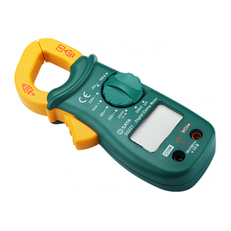
SATA 03021 User manual

EN PT JARU KODE ES
数字钳形万用表
Digital Clamp Multimeter
Digitalmultimeter Mit Backen
Multímetro digital
Цифровой мультиметр с клещами
디지털 집게형 만용시계
Multímetro digital tipo alicate
デジタルクランプオンマルチメータ
03021
사용설명서 \ Manual de instruções \ \ Manual del uso

ESPT JARUEN DE KO
03021
目录
简介 ………………………………………………………………………………………… 1
告诫………………………………………………………………………………… 2
电气符号…………………………………………………………………………… 3
一般特性 …………………………………………………………………… 3
电气特性 …………………………………………………………………… 4
交流电压 …………………………………………………………………… 4
直流电压 …………………………………………………………………… 4
交流电流 …………………………………………………………………… 5
电阻 ………………………………………………………………………… 6
相序测试 …………………………………………………………………… 6
通断和二极管测试 ………………………………………………………… 6
面板说明…………………………………………………………………………… 9
使用说明…………………………………………………………………………… 8
数据保持 …………………………………………………………………… 8
测量直流电压 ……………………………………………………………… 8
测量交流电压 ……………………………………………………………… 8
测量交流电流 ……………………………………………………………… 9
电阻测量 …………………………………………………………………… 9
通断测试 …………………………………………………………………… 9
二极管测试 ……………………………………………………………… 10
相序判别 ………………………………………………………………… 10
自动关机 ……………………………………………………………………11
保养…………………………………………………………………………………11
说明……………………………………………………………………………… 13

ESPT JARUEN DE KO
03021
-1-
简 介
本仪表是一款性能稳定,安全、可靠的自动量程3 1/2数字钳形万用表。可用于
测量交直流电压、交流电流、电阻、二极管和通断,并具有相序测试功能。仪表
具有数据保持、屏幕背光、全量程过载保护等特点,是一款实用的测量工具。
安全信息
本仪表的设计符合IEC-61010,污染等级2级,过电压标准CATI600V。
警告
- 为避免电击和人身伤害,请遵循以下操作要求:
- 应根据本手册所指定的方法使用仪表,否则仪表所提供的保护措施能会受
到损坏。
- 仪表存在破损时,请勿使用。使用前请检查外壳,尤其应注意连接器周围的
缘。
- 检查表笔的绝缘是否有损坏或暴露的金属。检查表笔是否导通。如果表笔
有损坏,请更换后再使用。
- 若仪表工作失常,请勿使用。保护设施可能已遭破坏。若有疑问,应把仪表
送去维修。
- 切勿在爆炸性的气体,蒸汽或灰尘附近使用本仪表。
- 切勿在端子之间或端子与地之间施加超过仪表上所标示的额定电压。
- 使用前,通过测量已知电压的方式确认仪表工作正常。
- 对于30Vac有效值,42Vac峰值或60Vdc以上的电压,工作时要小心,这类
电压会有电击的危险。
- 使用表笔时,应把手指置于表笔上的护指装置后。

ESPT JARUEN DE KO
03021
-2-
- 连接时,先连接公共测试导线,而后才连接带电的测试导线。
- 拆除接线时,先拆带电的测试导线,而后才拆除公共测试导线。
- 打开仪表电池盖或外壳之前,应先将表笔拆下。
- 仪表的电池盖或外壳的一部分被拆下或松开时,切勿使用仪表。
- 当屏幕出现电池低电压符号" "时,应马上更换电池。电池的电压不足
会使仪表读数错误,从而导致电击或人身伤害。
- 不要将随机配送的表笔用在其它仪器上。
- 当使用者的手或环境很潮湿,或当仪表很潮湿时,不要使用仪表。
- 给一个输入端子接上一个危险的电压时请注意,在所有其他端子上可能出现
此电压。
- CAT III:直接连接到配电盘的大型设备(固定设备)的一次线路及配电盘与
插座之间的电气线路。不要将本仪器用于属于的测量。
为避免对仪表或设备造成损害,请遵守以下几点要求:
- 在测量电阻和通断之前,先断开被测电路的电源,并对所有电容器进行充
分放电。
- 使用正确的端子,功能和量程。
- 打开电池盖或外壳前,先把表笔从仪表上取下。
- 移转动功能/档位开关前,应先使表笔和钳头从被测导体或电路上取下。
告诫

ESPT JARUEN DE KO
03021
-3-
电气符号
交流
直流
交流或直流
警惕!有危险,使用前请参阅说明书
地端子
回仪表有双重绝缘或加强绝缘保护
警惕!有电击危险
符合欧盟指标
可在危险的带电导体的周围使用或从危险的带电导体取下
一般特性
1. 显示屏:3 1/2位液晶显示屏,最大读数1999
2. 采样速率:约3次/秒
3. 负极性指示: 屏幕显示“—”
4. 过量程指示: 屏幕显示“OL”
5. 测试位置误差:测量电流时因未将被测导体置于钳头中央而产生1%的读数
误差
6. 钳头开启最大尺寸:直径30mm(近似值)
7. 预测电流导线最大尺寸:直径30mm(近似值)
8. 电池低电压指示:屏幕显示“ ”符 号

ESPT JARUEN DE KO
03021
-4-
9. 电源: 1.5V AAA电池,2只
10. 工作温度: 0℃~40℃,相对湿度:<75%
11. 贮存温度: -20℃~50℃,相对湿度:<85%
12. 尺寸: 185mm×74mm×40mm
13. 重量: 约195g(含电池)
电气特性
精度保证期限为一年,精度保证工作条件:温度8℃~28℃,相对湿度<75%
a)交流电压
量程 分辨率 精度
2.000V 1mV
±(1.2%+5)20.00V 10mV
200.0V 100 mV
600V 1V ±(1.5%+5)
输入阻抗:10MΩ
最大允许输入电压:600V
频率响应:40Hz—400Hz
AC转换类型:正弦波输入,平均值响应,读数校正至有效值。
b)直流电压

ESPT JARUEN DE KO
03021
-5-
量程 分辨率 精度
200.0 mV 0.1 mV ±(0.5%+5)
2.000V 1 mV
±(0.8%+5)20.00V 10 mV
200.0V 100 mV
600V 1V ±(1%+5)
输入阻抗:10MΩ
最大输入电压:600V
c)交流电流
量程 分辨率 精度
2.000A 0.001A
±(6%+20)≤0.4A
±(5%+10)
20.00A 0.01A
±(4%+10)≤4A
±(3%+8)
200.0A 0.1A ±(2.5%+5)
600A 1A ±(2.5%+5)
AC转换类型:正弦波输入、平均值响应,校正读数至与有效值一致。
频率:50-60Hz

ESPT JARUEN DE KO
03021
-6-
d)电 阻
量程 分辨率 精度
200.0Ω100mΩ±(1.2%+5)
2.000kΩ1Ω
±(1%+5)20.00kΩ10Ω
200kΩ100Ω
2.000MΩ1kΩ±(1.2%+5)
20.00MΩ10kΩ±(1.5%+5)
f) 通断和二极管测试
量程 分辨率 精度
100mΩ 当电阻≤约30Ω时,蜂鸣器产生蜂鸣
1mV 屏幕显示二极管正向压降的近似值。开
路电压:约1.48V
对于通断测试,当电阻在30Ω到120Ω时,蜂鸣器可能响或不响。电阻大于120Ω
时,蜂鸣器不响。
注意:
e)相序测试
测量范围 相序指示 相电压精度
380V±10%,50Hz 顺相、逆相、缺相 ±2%

ESPT JARUEN DE KO
03021
-7-
面板说明
1. 钳头
- 测量电流时,用于夹取待测导体。测量时,被测导体应位于钳头的中心位置。
2. 绝缘栅
- 用于在钳口形成一个防护距离,以减少手指触及到钳头或被测导体的危险。手
持仪表时,手指不能超过绝缘栅。
3. 板机
- 用于控制钳头的开启与闭合。
4. 相序指示灯
5. 显示屏
- 3 1/2位液晶显示,最大读数1999,带单位显示
6.“”插 孔
- 相序测试时,黄色表笔的输入插孔。
7. "COMb"插孔
- 黑色表笔的输入插孔。
8. " "插孔
- 红色表笔的输入插孔。
9.“”按 钮
- 按住该按钮不放约2秒可开启或关闭背光功能背光点亮后约15秒将自动关闭。
10. 功能/档位开关
- 该开关用于选择所需的功能和档位以及开启和关闭仪表的电源。
11. " "按钮
- 在二极管或通断测试功能,此按钮用于在二极管和通断测试功能之间切换。
- 在温度测试功能,此按钮用于在摄氏和华氏测试功能之间切换。
图1

ESPT JARUEN DE KO
03021
-8-
-在其它测试功能,此按钮用于数据保持。
使用说明
a)数据保持
在除了极管、通断和温度之外的其它功能,按一下“ ”按钮将锁定屏幕当前
读数屏幕将出现“ ”符号。再次按一下该按钮则取消锁定,同时“ ”符 号
消失。
b)测量直流电压
1. 将黑色表笔插到“ ”插孔,红色表笔插到“ ”插 孔 。
2. 将功能开关置于“ ”位 置 。
3. 将表笔跨接到待测电源或电路的两端。
4. 读取读数。红表笔连接端的极性也将同时指示。
注意:
注意:
为避免受到电击或造成仪表损坏,请勿将大于600V的电压加到输入端。
c)测量交流电压
1. 将黑色表笔插到“ ”插孔,红色表笔插到“ ”插 孔 。
2. 将功能开关置于“ ”位 置 。
3. 将表笔跨接到待测电源或电路的两端。
4. 读取读数
为避免受到电击或造成仪表损坏,请勿将大于600V的电压加到输入端。

ESPT JARUEN DE KO
03021
-9-
注意:
注意:
d)测量交流电流
1.先将所有表笔从仪表上取下,然后将功能开关设在所需的电流测量档位。
2. 按动扳机,用钳头夹取待测导体,然后缓慢地放开板机,直到钳头完全闭合
确保待测导体被夹取在钳头中央。仪表一次只能测量一个导体。若同时测量
两个或两个以上的导体,则会造成读数错误
3. 读取屏幕读数。
e)电阻测量
1. 将黑色表笔插到“ ”插孔,红色表笔插到" "插 孔 。
2. 将功能开关置于“ ”位 置 。
3. 将表笔跨接到待测电阻的两端。
4. 当读数稳定后,从屏幕上读取读数。
1. 当所测量的电阻值为1MΩ或1MΩ以上时,读数需要过几秒钟才能稳定,这
对高阻的测量是正常的。
2. 当输入端开路时,则显示过载。
3. 在测量在线电阻时,断开被测电路的所有电源,并对所有电容进行充分放
电。
f)通断测试
1. 将黑色表笔插到“ ”插孔,红色表笔插到“ ”插 孔 。
2. 把功能开关设定到“ ”位置。然后按动" "按钮直到屏幕显示电阻单位。
3. 将表笔跨接到待测电路的两端。

ESPT JARUEN DE KO
03021
-10-
4. 当电阻小于约30Ω时,内置蜂鸣器将响。
注意:
在测试之前,断开待测电路的所有电源,并对所有电容进行充分放电。
g)二极管测试
1. 将黑色表笔插到“ ”插孔,红色表笔插到“ ”插孔。(注意:红色表笔
的 极 性 为"+"。)
2. 把功能开关设定到“ ”位置。然后按动“ ”按钮直到屏幕显示电压
单位。
3. 将红色表笔接待测二极管的正极,黑色表笔接二极管的负极。
4. 从屏幕上读取被测二极管的正向压降的近似值。
h)相序判别
将功能开关置" "档。将红、黑、黄三只表笔按图2所示分别插入“ ” ,“ ”,
和“ ”三个插孔,然后将它们分别连接到三相电的接线端,将会出现:
情况1:
如图2连接,相序指示灯亮,说明连接为顺相序,相线相序为:c→b→a
情况2:
如果按图2连接后相序指示灯不亮,说明连接为逆相序,请按图3所示将红、黑表
笔的连接对调。如果相序指示灯亮,则相线相序为:c→a→b
情况3:
如果按图3连接后相序指示灯仍不亮,则按图4连接。如果相序指示灯亮,则相
线相序为:b→c→a。如果相序指示灯仍不亮,说明有缺相。缺相判断方法如下:若
显示值小于220V则缺a相;若显示值大于260V且小于350V则缺b相;若显示值约为

ESPT JARUEN DE KO
03021
-11-
380V,取消c相连接,此时如果屏幕显示电压不变,说明缺C相。
图2图3图4
i)自动关机
1. 仪表停止使用或停留在一个档位的时间超过15分钟时,仪表将自动关机,
仪表进入睡眠模式。
2. 当仪表自动关机后,若要唤醒仪表,请转动功能开关或者按一下按钮。
3. 如果功能/档位开关位于电压,电流或电阻档,当自动关机后,如果
按“ ”按钮唤醒仪表,则自动关机功能将被取消。
保养
除更换电池外,若非合格的专业技师并且拥有足够的校准、性能测试和维修仪表
的相关说明,切勿尝试修理或保养您的仪表.建议校准周期为12个月。
定期用潮湿布和少许清洁剂擦拭外壳。请勿使用磨料或溶剂。端子若弄脏或潮
湿可能会影响读数。
按以下步骤清洁端子:

ESPT JARUEN DE KO
03021
-12-
1. 关闭仪表并且取下测试导线。
2. 把端子内可能存在的灰尘摇掉。
3. 取一个新棉球沾上酒精,仔细清洁每个输入端子内部。
更换电池
当显示屏出现“ ”时,表示电池的电量不足,应及时更换。更换电池时,请卸下
电池盖上的螺丝,打开电池盖,用新的同种型号的电池更换旧电池,确保电池极
性正确。盖上电池盖,再锁紧螺丝。
警告:
打开电池盖或外壳前,必须先将表笔从仪表上取下。
开箱检查
包装内容
数字钳形表: 1台
测试表笔: 1副
1.5VAAA电池: 2节
使用说明书: 1本
保修卡: 1张

ESPT JARUEN DE KO
03021
-13-
说明
1. 本公司保留对说明书内容修改的权利。
2. 本公司不负责任何由于使用时引起的其它损失。
3. 本说明书内容不能作为将产品用做特殊用途的理由。

ESPT JARUDE KO
03021 EN
Contents
Introduction ………………………………………………………………………………………………………………………………………15
Warning …………………………………………………………………………………………………………………………………………………16
Electrical symbols…………………………………………………………………………………………………………………………17
General characteristics……………………………………………………………………………………………………………17
Electrical characteristics ………………………………………………………………………………………………………18
AC voltage ……………………………………………………………………………………………………………………………………19
DC voltage ……………………………………………………………………………………………………………………………………19
AC current ……………………………………………………………………………………………………………………………………19
Resistance ………………………………………………………………………………………………………………………………… 20
Phase sequence test……………………………………………………………………………………………………………… 20
Continuity and diode test ………………………………………………………………………………………………………21
Panel description …………………………………………………………………………………………………………………………21
Operating instruction …………………………………………………………………………………………………………… 22
Data hold …………………………………………………………………………………………………………………………………… 22
AC voltage measurement……………………………………………………………………………………………………… 22
AC measurement …………………………………………………………………………………………………………………… 23
Resistance measurement …………………………………………………………………………………………………… 23
Continuity test ………………………………………………………………………………………………………………………… 24
Diode test…………………………………………………………………………………………………………………………………… 24
Phase sequence judgment ………………………………………………………………………………………………… 25
Automatic power-off……………………………………………………………………………………………………………… 26
Servicing……………………………………………………………………………………………………………………………………………… 26
Description ……………………………………………………………………………………………………………………………………… 27

ESPT JARUEN DE KO
03021
-15-
Introduction
This meter is a safe and reliable 3 1/2-digit digital clamp multimeter with automatic
range and stable performance. It can be used for the measurement of AC/DC voltage,
AC, resistance, diode and continuity, and the test of phase sequence. It is a practical
measurement tool, with such features as data hold, screen backlight and full-range
overload protection.
Safety information
The meter is designed to conform to Pollution Degree 2 and Overvoltage Category
CATI600V as specified in IEC-61010.
Warning
- To avoid electric shock and personal injury, please follow the following operating
requirements:
- The meter shall be used with the method specified in this manual; otherwise,
protective measures provided by the meter may be damaged.
- Do not use the meter if it is damaged. Check the casing before use, especially the
insulation around the connectors.
- Check the insulation of the probes for damage or exposed metal. Check if the
test probes are conductive. If a test probe is damaged, please replace it with a
new one for continued operation.
- If the meter is not working properly, do not use it. Its protective device may have
been damaged. If you have any doubt, the meter should be sent for repair.
- Never use the meter near explosive gases, vapors or dust.
- Never apply a voltage greater than the rated voltage indicated on the meter
between the terminals or between the ground and any terminal.
- Before use, check that the meter is working properly by measuring a known
voltage.
- Use only designated replacement parts during repair.
- Exercise caution when working with voltages above 30Vac rms, 42Vac peak or
60Vdc. These voltages pose a shock hazard.
- When using the probes, keep your fingers behind the finger guards.

ESPT JARUDE KO
03021
-16-
EN
- During connection, connect the common test lead before the live test lead.
- When removing the wiring, remove the live test lead before the common test lead.
- Remove the probes before opening the battery cover or meter casing.
- Do not use the meter when the battery cover or a part of the casing is removed or
loosened.
- When the low battery voltage symbol “ ” appears on the screen, replace the battery
- immediately. Low battery voltage can cause false readings, resulting in electric shock
or personal injury.
- Do not use the probes included in the meter on other meters.
- Do not use the meter when the user's hand or environment is humid, or when the meter
is humid.
- When a dangerous voltage is supplied to an input terminal, please note that this
voltage may be supplied to all the other terminals.
- CAT III: Primary circuit of large equipment (fixed equipment) directly connected to the
switchboard and electrical circuit between the switchboard and the outlet. Do not use
this meter for measurements that fall within CAT IV.
- To avoid damage to the meter or equipment, please observe the following
requirements:
- Before measuring resistance and continuity, switch off the power of the
measured circuit and fully discharge all capacitors.
- Use the correct terminals, functions and ranges.
- Remove the probes from the meter before opening the battery cover or meter
casing.
- Remove the probes and head from the measured conductor or circuit before
rotating the function/position switch.
Warning

ESPT JARUDE KO
03021
-17-
EN
Electrical symbols
AC
DC
AC or DC
Caution! Danger! Please read the instruction before use.
Ground terminal
Meter with double or strengthened insulation protection
Caution! Risk of electric shock!
In compliance with EU Directives
Use around or removal from hazardous live conductors
General characteristics
1. Display: 3 1/2-digit LCD, with a maximum reading of 1999
2. Sampling rate: about 3 times/s
3. Negative polar indication: “-” shown on the screen
4. Overrange indication: “OL” shown on the screen
5. Test position error: reading error of 1% caused by failure to place the measured
conductor in the center of head during current measurement
6. Maximum opening dimension of head: diameter: 30mm (approximation)
7. Maximum dimension of predictive current lead: diameter: 30mm (approximation)
8. Low battery voltage indication: “ ” shown on the screen
9. Power: 1.5V AAA batteries, 2 PCS
10. Operating temperature: 0°C ~ 40°C; relative humidity: < 75%

ESPT JARUDE KO
03021
-18-
EN
11. Storage temperature: -20°C~50°C; relative humidity: <85%
12. Dimension: 185mm×74mm×40mm
13. Weight: about 195g (including battery)
Electrical characteristics
Period of accuracy guarantee: 1 year, operating conditions of accuracy guarantee:
temperature: 8°C~28°C; relative humidity < 75%
a) AC voltage
Range Resolution Accuracy
2.000V 1mV
±(1.2%+5)20.00V 10mV
200.0V 100 mV
600V 1V ±(1.5%+5)
Input impedance: 10MΩ
Maximum allowable input voltage: 600V
Frequency response: 40Hz~400Hz
AC conversion type: correct readings to be consistent with RMS values by sine-wave
input and average responding.
b) DC voltage
Table of contents
Languages:
Other SATA Multimeter manuals