Circuit-test DMR-4350 User manual

USER'S MANUAL
DIGITAL MULTIMETER
DMR-4350
CIRCUIT-TEST ELECTRONICS
www.circuittest.com

– 1 –
TABLE OF CONTENTS
SAFETY
Safety Information . . . . . . . . . . . . . . . . . . . . . . . . . . . . . . . . . . . . . . 2
Safety Symbols . . . . . . . . . . . . . . . . . . . . . . . . . . . . . . . . . . . . . . . . 3
INTRODUCTION
LCD Symbol Definitions . . . . . . . . . . . . . . . . . . . . . . . . . . . . . . . . . 4
Front Panel Description. . . . . . . . . . . . . . . . . . . . . . . . . . . . . . . . . . 5
SPECIFICATIONS
General . . . . . . . . . . . . . . . . . . . . . . . . . . . . . . . . . . . . . . . . . . . . . . 6
Ranges and Accuracy . . . . . . . . . . . . . . . . . . . . . . . . . . . . . . . . . . . 7
OPERATING INSTRUCTIONS
Understanding True RMS . . . . . . . . . . . . . . . . . . . . . . . . . . . . . . . . 8
Auto Power Off Feature. . . . . . . . . . . . . . . . . . . . . . . . . . . . . . . . . . 8
Analog Bargraph Display. . . . . . . . . . . . . . . . . . . . . . . . . . . . . . . . . 8
1. DC Voltage Measurement . . . . . . . . . . . . . . . . . . . . . . . . . . . . . 9
2. AC Voltage Measurement . . . . . . . . . . . . . . . . . . . . . . . . . . 9-10
3. DC Current Measurement . . . . . . . . . . . . . . . . . . . . . . . . . .10-11
a) less than 326mA DC current
b) 326mA or more DC current
4. AC Current Measurement . . . . . . . . . . . . . . . . . . . . . . . . . .11-13
a) less than 326mA DC current
b) 326mA or more AC current
5. Resistance Measurement . . . . . . . . . . . . . . . . . . . . . . . . . . . . 13
6. Continuity Test . . . . . . . . . . . . . . . . . . . . . . . . . . . . . . . . . . . . . 14
7. Diode Test . . . . . . . . . . . . . . . . . . . . . . . . . . . . . . . . . . . . . 14-15
8. Temperature Measurement . . . . . . . . . . . . . . . . . . . . . . . . . . . 15
9. Range Function . . . . . . . . . . . . . . . . . . . . . . . . . . . . . . . . . . . . 16
10. Hold Function . . . . . . . . . . . . . . . . . . . . . . . . . . . . . . . . . . . . . 16
11. Battery Replacement . . . . . . . . . . . . . . . . . . . . . . . . . . . . . . . . 17
12. Fuse Replacement . . . . . . . . . . . . . . . . . . . . . . . . . . . . . . 17-18
MAINTENANCE. . . . . . . . . . . . . . . . . . . . . . . . . . . . . . . . . . . . . . . . . . . 19
ACCESSORIES . . . . . . . . . . . . . . . . . . . . . . . . . . . . . . . . . . . . . . . . . . . 19
WARRANTY. . . . . . . . . . . . . . . . . . . . . . . . . . . . . . . . . . . . . . . . . . . . . . 19

– 2 –
SAFETY INFORMATION
This meter is CUL and UL approved and conforms to IEC 61010-1 for Cat-
egory III - 600V and Category II - 1000V. This meter is designed to be safe
under the following conditions: indoor use, altitude up to 2000m, temperature
5°C to 40°C, maximum relative humidity 80% for temperatures up to 31°C
decreasing linearly to 50% relative humidity at 40°C and rated pollution
degree 2. Caution and proper guidelines must be followed for personal
and product safety. Read this instruction manual carefully and completely
before using the meter. Lack of caution or poor safety practices can result
in serious injury or death.
• This meter is not recommended for high voltage industrial use; for
example, do not use for measurement on 440VAC or 600VAC industrial
power mains. The unit is intended for use with low energy circuits up to
600VDC / 600VAC or high energy circuits up to 250VAC / 250VDC only.
• Use caution when working above 60VDC or 30VAC RMS as these volt-
ages pose a shock hazard.
• Always consider circuits to be energized. Never assume any equipment
to be de-energized.
• Always start with power off. Set the function switch to the correct setting
before making any measurements and do not change position of the
function switch during measurements.
• Never connect unit to AC or DC powered circuits when the function
switch is set to resistance, diode check or continuity ranges.
• Always disconnect the power when performing resistance, diode or
capacitance tests. Discharge capacitor before testing.
• Disconnect the live/positive test lead (red) prior to disconnecting the
common/negative test lead (black).
• When appears on the display, change both batteries to achieve
more accurate readings.
• Disconnect the test leads before removing the batteries or the fuse.
• Do not operate the unit unless the case is completely closed.
• When using the test probes always keep fingers behind the finger
guards. Never touch the exposed probe tip.
• Always inspect the instrument, test leads and other accessories for
damage prior to use.
• Use only UL recognized test leads (included with this meter).

– 3 –
SAFETY SYMBOLS
Safety symbols and special annunciators on the meter and in this manual
indicate cautions and warnings of important operational procedures that must
be followed to ensure personal and product safety.
This symbol indicates a General Warning. When adjacent to a termi-
nal or operating device indicates that the operator must refer to an
explanation in the Operating Instructions.
500V
MAX
This symbol indicates that the terminal(s) so marked must not be con-
nected to a circuit point at which the voltage with respect to ground
exceeds 500V AC/DC.
This symbol adjacent to one or more terminals indicates them as
being associated with ranges that may in normal use, be subjected
to particularly hazardous voltages. For maximum safety, the meter
and its test leads should not be handled when these terminals are
energized.
This meter is protected by double insulation. Service this meter by a
professional only.

– 4 –
INTRODUCTION
DMR-4350 is a True RMS Auto Ranging meter featuring an analog bargraph
for easy viewing of measurement changes. This meter can measure/test
the following:
– Voltage – Current
– Resistance – Continuity
– Diode – Temperature
LCD DISPLAY SYMBOL DEFINITIONS
DISPLAY/SYMBOL DEFINITION DISPLAY/SYMBOL DEFINITION
Diode AAmps
Data Hold Range Hold
AC Alternating Current Low Battery
Continuity VVolts
°F Degree Fahrenheit MMega
°C Degree Celsius KKilo
µMicro Ohms
mmilli OL Over Range
|||||||||||Analog Bargraph
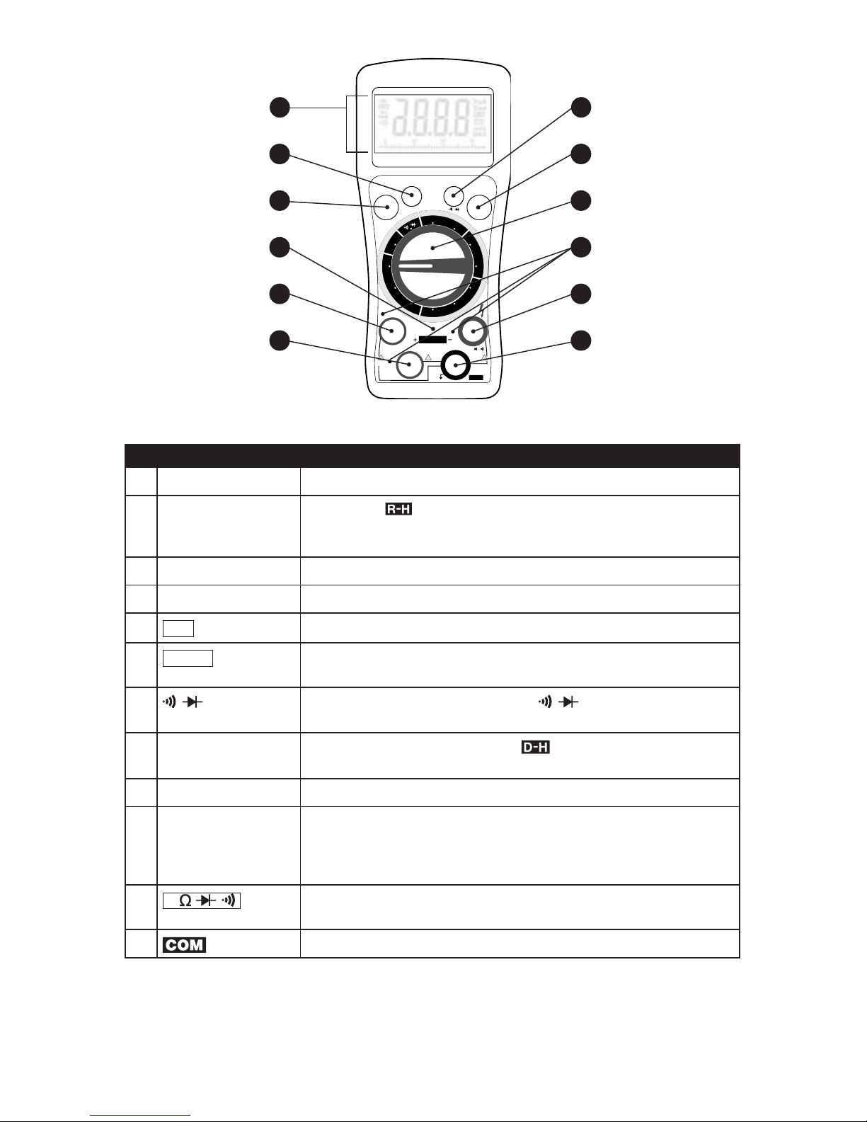
– 5 –
NO. ITEM DESCRIPTION
1LCD Display 3-3/4 digit 3200 count LCD Display
2RANGE Button Indicated by on the LCD display. Overrides the Auto Ranging
feature. Starts with displaying the lowest range in manual mode. This
function works for AC/DC Volts, AC/DC Current and Ohms mode.
3Power Button Power ON/OFF push button switch
4Temperature Jack Plug in 'K' type thermocouple observing the polarity
520A Jack Positive input jack to plug in red test lead for 20A measurement only.
6µA/mA Jack Positive input jack to plug in red test lead for current measurement
up to 326mA
7/ Button When the function switch is turned to / , use this pushbutton to
select between continuity and diode tests
8HOLD Button The displayed data will freeze and will appear on the LCD.
Changes in the input signal will not change the display.
9FUNCTION Switch Function Switch to select measurement mode
10 Test Lead Input
Indicating LEDs
Lighted LED indicates the correct jack to plug in the test lead for the
selected function. LED will turn off after the test lead is fully inserted.
If the test lead is incorrectly plugged in, the LED will start blinking
and buzzer will sound.
11 V/ / / Jack Positive input jack to plug in red test lead for voltage, resistor, diode
and continuity check.
12 Jack Plug in black test lead in all measurement modes, common ground
TEMP
POWER
CIRCUIT-TEST DMR-4350
20A
RANGE
µA/mA
HOLD
1000 VDC
750 VAC
CAT III 600V
CAT II 1000V
FUSED
320mA
MAX
500V
MAX
for 15 sec MAX
every 30 min
AUTO
POWER
OFF
FUSED
20A MAX
!!!
V/Ω/ /
Ω
/
COM
TRUE RMS
F°
C°
DCV
ACV
µA
mA
20A
µA
mA
20A
T
E
M
P
A
C
A
M
P
S
D
C
A
M
P
S
V
O
L
T
S
O
H
M
S
12
11
10
9
8
7
6
5
4
3
2
1
FRONT PANEL DESCRIPTION

– 6 –
SPECIFICATIONS
GENERAL
Display: 3 3/4 digit 3200 count LCD
Maximum Display: 3200
Ranging: Auto/Manual
Auto Shut-off: Meter will shut-off after 10 minutes from last use
Polarity: Automatic, minus (-) sign indicates negative polar-
ity, no sign for positive polarity
Measuring rate: 3 times/sec
Input impedance: 10M (DCV / ACV)
Diode Test: Test current of 1.0 mA maximum
Continuity: Audible signal sounds if resistance is less than
20
Over range indication: ʻOLʼ is displayed
Operating Temp: 5 to 40° C (41 to 104° F)
Storage Temp: -10 to 50° C (14 to 122° F)
Relative Humidity: <75% Operating/Storage
Power Source: 2 x AAA 1.5V Battery
Fuse: 0.5A/250V (5x20mm Fast Acting),
16A/500V (6.3x32mm Fast Acting Ceramic)
Temperature Probe: 'K' Type Thermocouple rated at 0° to 260°C
(-32° to 500°F) [model no. TL-190]
Dimensions: 185(H) x 90(W) x 45(D) mm
(75/16 x 31/2 x 113/16")
Weight: 347g (12.25 oz)
Accessories included: One pair of test leads, ʻKʼ type thermocouple,
Screw-on Alligator Clips, 2 x AAA batteries,
Userʼs manual

– 7 –
RANGES AND ACCURACY
FUNCTION RANGE RESOLUTION ACCURACY
DC VOLTAGE
(DC V)
326mV
3.26V
32.6V
326V
1000V
0.1mV
1mV
10mV
100mV
1V
±(0.5% reading + 5 digits)
AC VOLTAGE
(AC V)
3.26V
32.6V
326V
750V
1mV
10mV
100mV
1V
±(0.8% reading + 8 digits)
DC CURRENT
(DC A)
326µA
3.26mA
32.6mA
326mA
20A
100nA
1µA
10µA
100µA
10mA
±(1.2% reading + 5 digits)
±(2% reading +8 digits)
AC CURRENT
(AC A)
(40-400HZ)
326µA
3.26mA
32.6mA
326mA
20A
100nA
1µA
10µA
100µA
10mA
±(1.5% reading + 5 digits)
±(3% reading + 5 digits)
RESISTANCE 326
3.26k
32.6k
326k
3.26M
32.6M
0.1
1
10
100
1k
10k
±(0.8% reading + 5 digits)
±(3% reading + 10 digits)
TEMP °C -23 to 1000°C 1°C ±(1% reading + 6 digits)
TEMP °F -10 to 1830°F 1°F ±(1% reading + 8 digits)
NOTE: Accuracy consists of: (% reading i.e. accuracy of the measurement circuit +
digits i.e. accuracy of the analog to digital converter)
Reference conditions: 23°C ± 2°C, 40-60% Relative Humidity

– 8 –
OPERATING INSTRUCTIONS
This meter comes with an exclusive patented technology featuring bright
LEDs indicating the correct input jack to plug-in the positive (red) test lead
for the selected function. The LED turns off after the test lead is completely
plugged in the correct jack. If the test lead is plugged in the wrong jack, the
LED will start flashing and the buzzer will start beeping.
AUTO POWER OFF FEATURE
This meter turns off automatically if more than 10 minutes elapses between
uses. The meter will give an audible sound before turning off.
To turn the meter back ON once it powers off, press the POWER button
twice, or press the HOLD button or RANGE button once.
ANALOG BARGRAPH DISPLAY
Besides the digital readout, this meter also indicates all the measurements
on the bargraph at the bottom of the display. The bargraphʼs length increases
and decreases with the measured value making it easy to view the changes
in the measurement immediately.
UNDERSTANDING AC ZERO INPUT BEHAVIOR OF TRUE RMS
When measuring the AC voltage and current, the meter is calculating the
input and converting them to the data that the LCD can display. The converter
needs a certain level of the input voltage to make the measurement. This level
is 5% of the ranges for this meter. So the non-zero digits that are displayed
on the meter when the test leads are open or shorted are normal. They do
not affect the specified AC accuracy above 5% of the ranges.
– 9 –
1. DC VOLTAGE MEASUREMENT
WARNING: MAXIMUM INPUT IS 1000V DC. USE EXTREME CAUTION WHEN WORKING
WITH HIGH VOLTAGES. NEVER APPLY THE TEST LEAD TO THE MEASURING CIRCUIT WHEN
CHANGING THE POSITION OF THE FUNCTION SWITCH.
NOTE: The meter will be Auto ranging for this function. If you wish to measure with
Manual range, follow instructions described in Section 9. For manual ranging, start at
the highest range and work down.
➔ Set the function switch to DC V.
➔ ʻmVʼ appears on the display and the LED next to
V/ / / jack turns on.
➔ Plug the red test lead in V/ / / jack and
black test lead in jack.
➔ Apply the test leads to the circuit
to be measured. Ensure that the
black lead is connected to the
negative side of the circuit and red
lead to the positive.
➔ Read the displayed voltage.
➔ If the minus (-) sign appears it
means the voltage is negative at
the point being measured.
➔ If ʻOLʼ appears on the display, it indicates over-range. Immediately re-
move test leads from the measuring circuit to avoid any damage to the
meter. The input voltage should not exceed the measurement capability
of this meter.
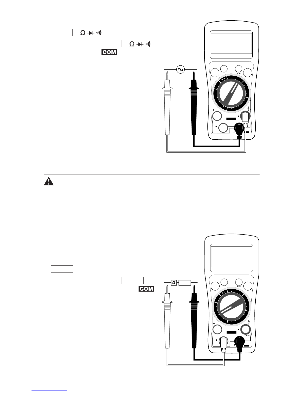
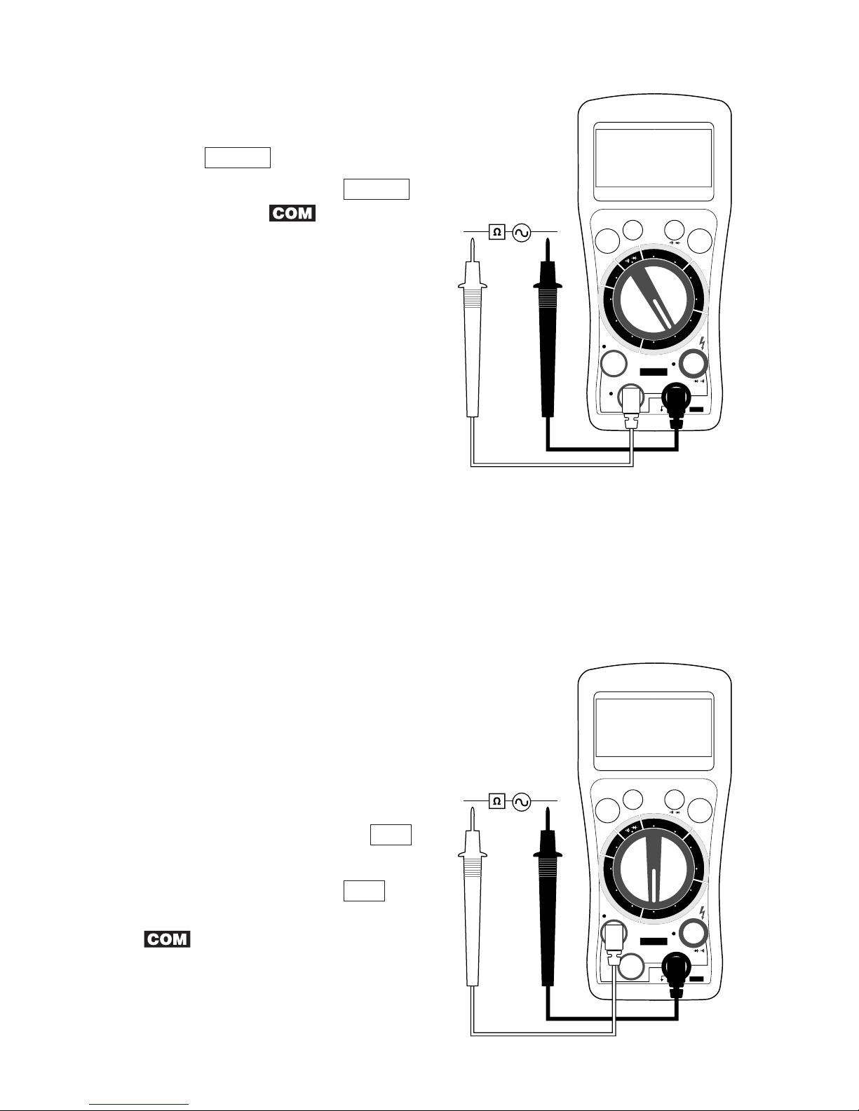
2. AC VOLTAGE MEASUREMENT
WARNING: MAXIMUM INPUT IS 750V AC. USE EXTREME CAUTION WHEN WORKING
WITH HIGH VOLTAGES. NEVER APPLY TEST LEADS TO THE MEASURING CIRCUIT WHEN
CHANGING THE POSITION OF THE FUNCTION SWITCH.
NOTE: The meter will be Auto ranging for this function. If you wish to measure with
Manual range, follow instructions described in Section 9. For manual ranging, start at
the highest range and work down.
➔ Set the function switch to AC V.
COM
TEMP
POWER
CIRCUIT-TEST DMR-4350
20A
RANGE
µA/mA
HOLD
V/Ω/ /
Ω
/
F°
C°
DCV
ACV
µA
mA
20A
µA
mA
20A
T
E
M
P
A
C
A
M
P
S
D
C
A
M
P
S
V
O
L
T
S
O
H
M
S
+ DC –
– 10 –
➔ ʻACʼ and ʻVʼ appear on the display and the LED
next to V/ / / jack turns on.
➔ Plug the red test lead in V/ / / jack and
black test lead in jack.
➔ Apply the test leads to the circuit to
be measured.
➔ Read the displayed TRMS voltage.
➔ If ʻOLʼ appears on the display, it
indicates over-range. Immediately
remove test leads from the measur-
ing circuit to avoid any damage to
the meter. The input voltage should
not exceed the measurement capa-
bility of this meter.
3. DC CURRENT MEASUREMENT
WARNING: WHEN MEASURING CURRENT REMOVE ALL POWER FROM THE CIRCUIT
BEING TESTED. NEVER APPLY THE TEST LEAD TO THE MEASURING CIRCUIT WHEN CHANG-
ING THE POSITION OF THE FUNCTION SWITCH.
NOTE: The meter will be Auto ranging for this function. If you wish to measure with
Manual range, follow instructions described in Section 9. For manual ranging, start at
the highest range and work down.
a) Less than 326mA DC Current Measurement
➔ Set the function switch to mA.
➔ ʻmAʼ appears on the display and the LED next to
µA/mA jack turns on.
➔ Plug the red test lead in µA/mA
jack and black test lead in the
jack.
➔ Remove power from the circuit that
is to be measured. Open up the
circuit and connect the black lead to
the negative side and the red lead
to the positive side of the circuit so
that the test leads are in series with
the load to be measured.
COM
TEMP
POWER
CIRCUIT-TEST DMR-4350
20A
RANGE
µA/mA
HOLD
V/Ω/ /
Ω
/
F°
C°
DCV
ACV
µA
mA
20A
µA
mA
20A
T
E
M
P
A
C
A
M
P
S
D
C
A
M
P
S
V
O
L
T
S
O
H
M
S
COM
TEMP
POWER
CIRCUIT-TEST DMR-4350
20A
RANGE
µA/mA
HOLD
V/Ω/ /
Ω
/
F°
C°
DCV
ACV
µA
mA
20A
µA
mA
20A
T
E
M
P
A
C
A
M
P
S
D
C
A
M
P
S
V
O
L
T
S
O
H
M
S
+ DC –
– 11 –
➔ Apply power to the circuit.
➔ Read the displayed current.
➔ If the numeral value in the display is too small, change the function
switch from mA to µA for a more sensitive measurement range.
➔ If ʻOLʼ appears on the display, it indicates over-range. Immediately remove
test leads from the measuring circuit to avoid any damage to the meter.
b) 326mA or more DC Current Measurement
CAUTION! Do not exceed 15 seconds when measuring the 20A range and
wait for 30 minutes between each measurement.
➔ Set the function switch to 20A.
➔ ʻAʼ appears on the display and the LED above
20A jack turns on.
➔ Plug the red test lead in 20A jack and
black test lead in the jack.
➔ Remove power from the circuit that
is to be measured. Open up the
circuit and connect the black lead to
the negative side and the red lead
to the positive side of the circuit so
that the test leads are in series with
the load to be measured.
➔ Apply power to the circuit.
➔ Read the displayed current.
➔ If ʻOLʼ appears on the display, it indicates over-range. Immediately
remove test leads from the measuring circuit to avoid any damage to
the meter.
4. AC CURRENT MEASUREMENT
WARNING: WHEN MEASURING CURRENT REMOVE ALL POWER FROM THE CIRCUIT
BEING TESTED. NEVER APPLY THE TEST LEAD TO THE MEASURING CIRCUIT WHEN CHANG-
ING THE POSITION OF THE FUNCTION SWITCH.
NOTE: The meter will be Auto ranging for this function. If you wish to measure with
Manual range, follow instructions described in Section 9. For manual ranging, start at
the highest range and work down.
COM
TEMP
POWER
CIRCUIT-TEST DMR-4350
20A
RANGE
µA/mA
HOLD
V/Ω/ /
Ω
/
F°
C°
DCV
ACV
µA
mA
20A
µA
mA
20A
T
E
M
P
A
C
A
M
P
S
D
C
A
M
P
S
V
O
L
T
S
O
H
M
S
+ DC –
– 12 –
COM
TEMP
POWER
CIRCUIT-TEST DMR-4350
20A
RANGE
µA/mA
HOLD
V/Ω/ /
Ω
/
F°
C°
DCV
ACV
µA
mA
20A
µA
mA
20A
T
E
M
P
A
C
A
M
P
S
D
C
A
M
P
S
V
O
L
T
S
O
H
M
S
a) Less than 326mA AC Current Measurement
➔ Set the function switch to mA.
➔ ʻACʼ and ʻmAʼ appear on the display and the LED
next to µA/mA jack turns on.
➔ Plug the red test lead in µA/mA jack and black
test lead in the jack.
➔ Remove power from the circuit that
is to be measured. Open up the
circuit and connect the black lead to
the negative side and the red lead
to the positive side of the circuit so
that the test leads are in series with
the load to be measured.
➔ Apply power to the circuit.
➔ Read the displayed current.
➔ If the numeral value in the display is too small, change the function
switch from mA to µA for a more sensitive measurement range.
➔ If ʻOLʼ appears on the display, it indicates over-range. Immediately
remove test leads from the measuring circuit to avoid any damage to
the meter.
b) 326mA or more AC Current Measurement
CAUTION! Do not exceed 15 seconds when measur-
ing the 20A range and wait for 30 minutes between
each measurement.
➔ Set the function switch to 20A.
➔ ʻACʼ and ʻAʼ appear on the
display and the LED above 20A
jack turns on.
➔ Plug the red test lead in 20A
jack and black test lead in the
jack.
➔ Remove power from the circuit
that is to be measured. Open up the
circuit and connect the black lead to
COM
TEMP
POWER
CIRCUIT-TEST DMR-4350
20A
RANGE
µA/mA
HOLD
V/Ω/ /
Ω
/
F°
C°
DCV
ACV
µA
mA
20A
µA
mA
20A
T
E
M
P
A
C
A
M
P
S
D
C
A
M
P
S
V
O
L
T
S
O
H
M
S
– 13 –
the negative side and the red lead to the positive side of the circuit so
that the test leads are in series with the load to be measured.
➔ Apply power to the circuit.
➔ Read the displayed current.
➔ If ʻOLʼ appears on the display, it indicates over-range. Immediately remove
test leads from the measuring circuit to avoid any damage to the meter.
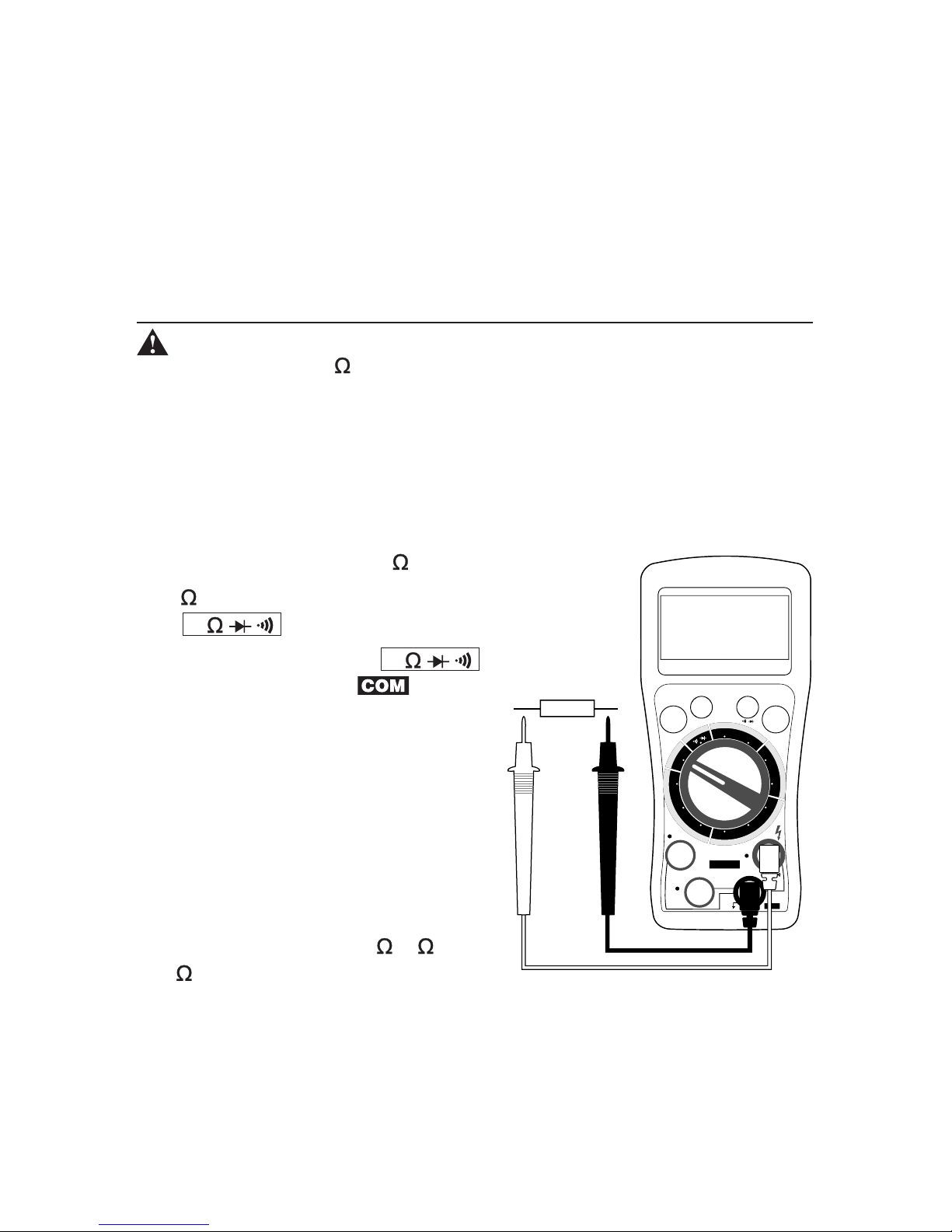
5. RESISTANCE MEASUREMENT
WARNING: NEVER CONNECT THE TEST LEAD TO ANY VOLTAGE WHEN THE FUNC-
TION SWITCH IS SET TO . REMOVE ALL POWER FROM THE CIRCUIT BEING TESTED
WHEN CHECKING RESISTANCE. DISCHARGE ANY CHARGED CAPACITORS. NEVER APPLY
THE TEST LEAD TO THE MEASURING CIRCUIT WHEN CHANGING THE POSITION OF THE
FUNCTION SWITCH.
NOTE: The meter will be Auto ranging for this function. If you wish to measure with
Manual range, follow instructions described in Section 9. For manual ranging, start at
the highest range and work down.
➔ Set the function switch to .
➔ ʻMʼ appears on the display and the LED next
to V/ / / jack turns on.
➔ Plug the red test lead in V/ / / jack
and black test lead in jack.
➔ Apply the test leads to the resistor
being measured. If the resistor is
part of a circuit, it is necessary to
disconnect one end of the resistor
to avoid any unwanted interference
from the rest of the circuit.
➔ Read the displayed resistance
indicated with proper decimal point
and one of the symbols , K or
M .
COM
TEMP
POWER
CIRCUIT-TEST DMR-4350
20A
RANGE
µA/mA
HOLD
V/Ω/ /
Ω
/
F°
C°
DCV
ACV
µA
mA
20A
µA
mA
20A
T
E
M
P
A
C
A
M
P
S
D
C
A
M
P
S
V
O
L
T
S
O
H
M
S
RESISTOR
– 14 –
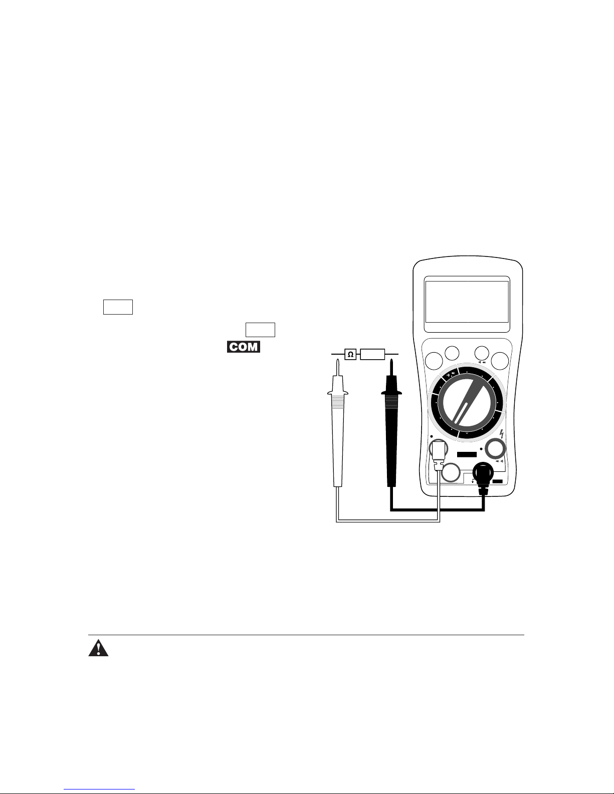
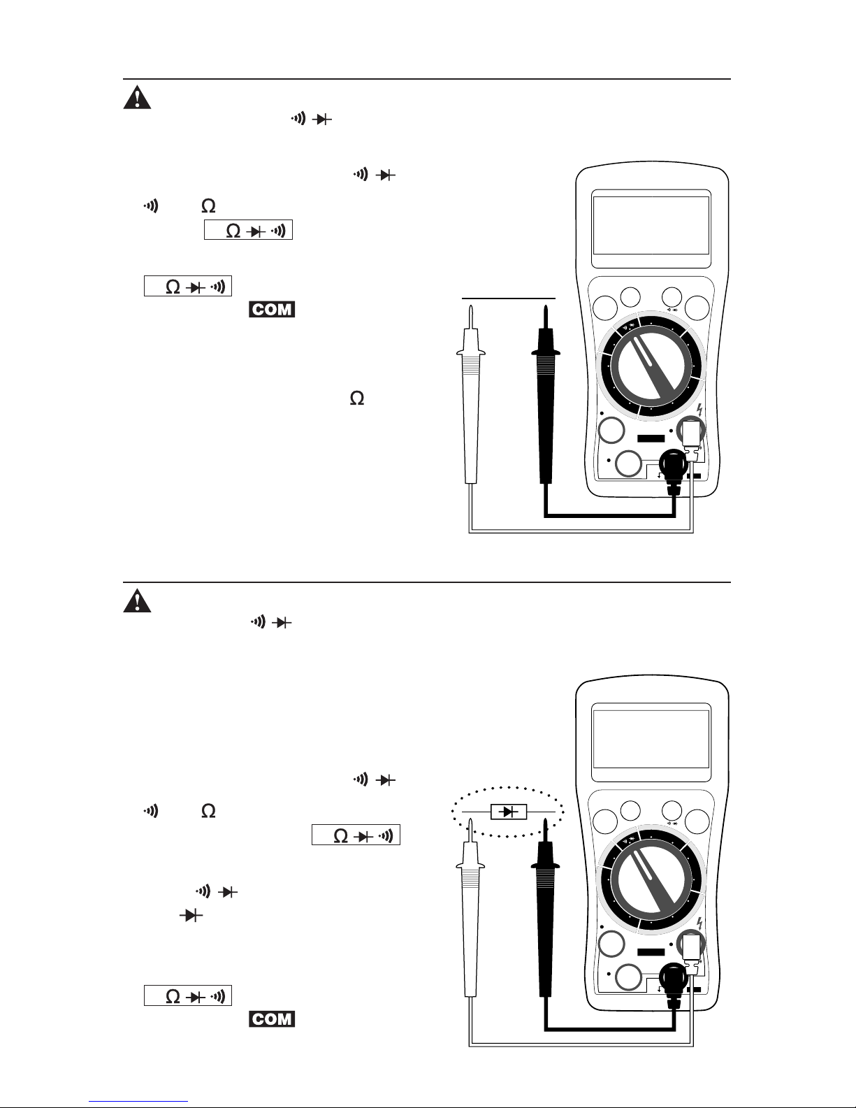
6. CONTINUITY TEST
WARNING: NEVER CONNECT THE TEST LEADS TO ANY VOLTAGE WHEN THE FUNC-
TION SWITCH IS SET TO /. REMOVE ALL POWER FROM THE CIRCUIT BEING TESTED
WHEN CHECKING RESISTANCE. DISCHARGE ANY CHARGED CAPACITORS.
➔ Set the function switch to /.
➔ and appear on the display and the LED
next to V/ / / jack turns on.
➔ Plug the red test lead into the
V/ / / jack and the black test
lead into the jack.
➔ Apply the test leads to the circuit.
➔ The buzzer will sound if the
resistance is less than 20 and
the measured resistance value will
be displayed in ohms with proper
decimal point.
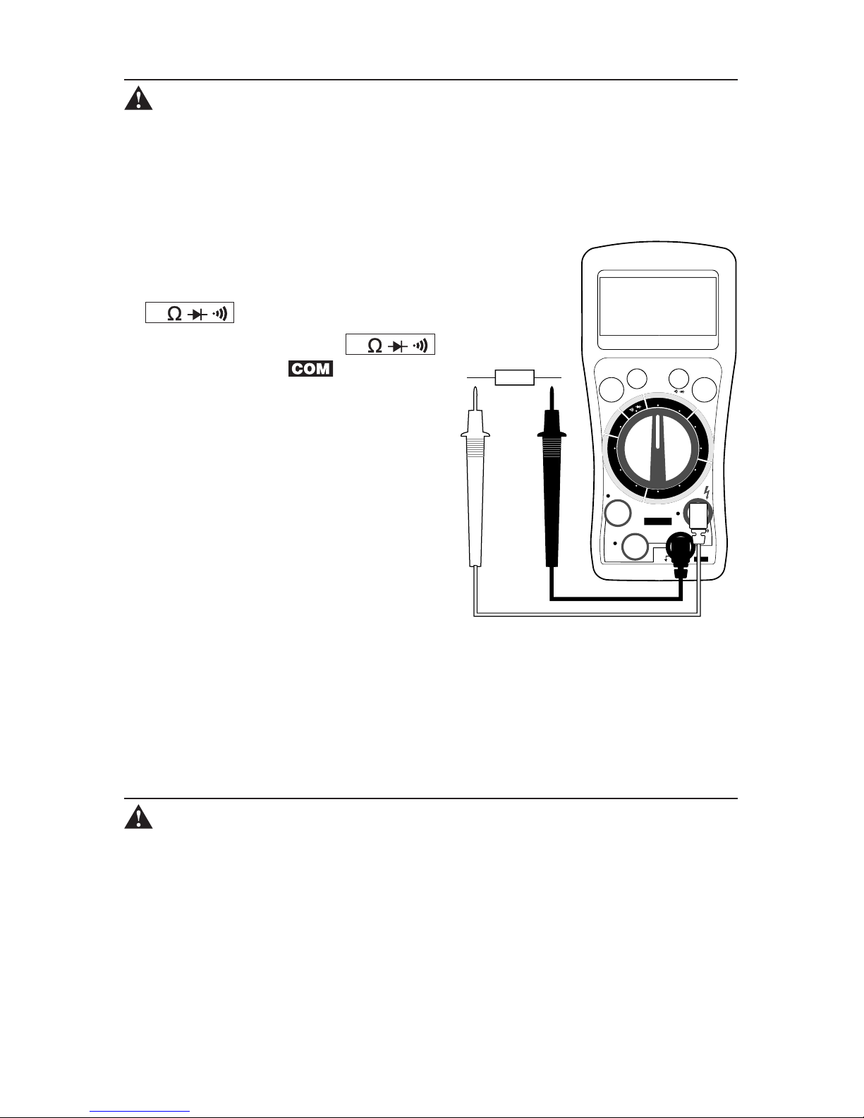
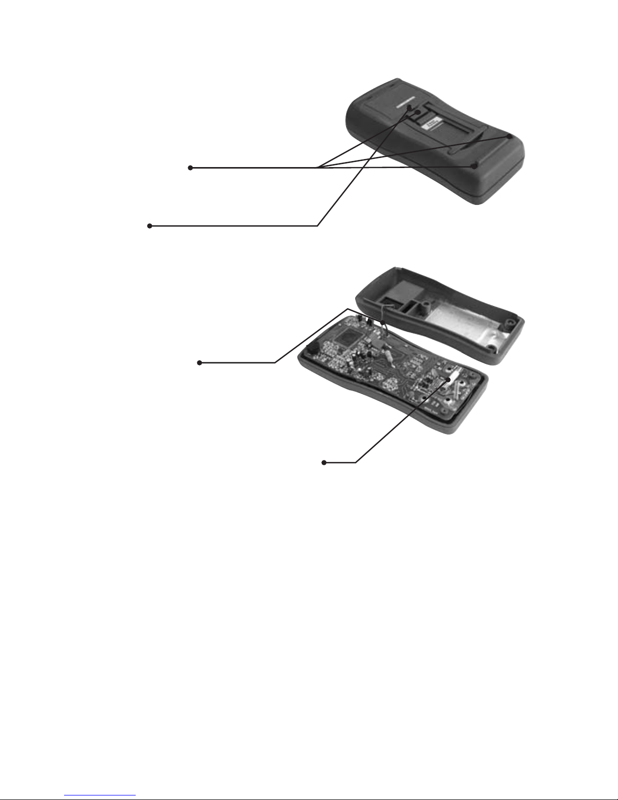
7. DIODE TEST
WARNING: NEVER CONNECT THE TEST LEAD TO ANY VOLTAGE WHEN THE FUNCTION
SWITCH IS SET TO / . REMOVE ALL POWER FROM THE CIRCUIT BEING TESTED WHEN
PERFORMING THE DIODE TEST. DISCHARGE ANY CHARGED CAPACITORS.
Note: If the diode is part of a circuit, it is necessary to discon-
nect one end of the diode to avoid any unwanted interference
from the rest of the circuit. The value indicated in the display
during the diode check is the forward bias voltage.
➔ Set the function switch to /.
➔ and appear on the display
and the LED next to V/ / /
jack turns on.
➔ Press / pushbutton once
and and ʻVʼ will appear on the
display.
➔ Plug the red test lead into the
V/ / / jack and the black test
lead into the jack.
COM
TEMP
POWER
CIRCUIT-TEST DMR-4350
20A
RANGE
µA/mA
HOLD
V/Ω/ /
Ω
/
F°
C°
DCV
ACV
µA
mA
20A
µA
mA
20A
T
E
M
P
A
C
A
M
P
S
D
C
A
M
P
S
V
O
L
T
S
O
H
M
S
COM
TEMP
POWER
CIRCUIT-TEST DMR-4350
20A
RANGE
µA/mA
HOLD
V/Ω/ /
Ω
/
F°
C°
DCV
ACV
µA
mA
20A
µA
mA
20A
T
E
M
P
A
C
A
M
P
S
D
C
A
M
P
S
V
O
L
T
S
O
H
M
S
WIRE

– 15 –
➔ Apply the test leads across the diode terminals and note the
meter reading.
➔ Reverse the diode and note this reading. Based
on the readings the result can be
evaluated as follows:
– If one reading is around 0.5
and the other reading is ʻOLʼ,
the diode is good
– If both readings are ʻOLʼ, the
diode is open (defective)
– If both readings are very
small or 0 (zero), the diode is
shorted (defective)
8. TEMPERATURE MEASUREMENT
WARNING: REMOVE ALL VOLTAGE SOURCES FROM THE CIRCUIT TO BE TESTED
BEFORE TAKING A TEMPERATURE MEASUREMENT. DO NOT MEASURE TEMPERATURES OF
METAL PARTS WITH A VOLTAGE ON THEM.
➔ Set the function switch to °C or °F depending on
whether the temperature is to be measured in
degrees Celsius or degrees Fahrenheit.
➔ Plug the ʻKʼ type thermocouple in the TEMP
jack.
NOTE: The ‘K’ type thermocouple supplied with this meter
is rated at 0° to 260°C (-32° to 500°F), although the meter is
capable of measuring up to 1000°C (1830°F).
➔ Touch the probe tip to the component you are
testing and keep it there for about 30 seconds or
until the reading stabilizes.
➔ The digital reading will display the value in
proper decimal point & value.
COM
TEMP
POWER
CIRCUIT-TEST DMR-4350
20A
RANGE
µA/mA
HOLD
V/Ω/ /
Ω
/
F°
C°
DCV
ACV
µA
mA
20A
µA
mA
20A
T
E
M
P
A
C
A
M
P
S
D
C
A
M
P
S
V
O
L
T
S
O
H
M
S
COM
TEMP
POWER
CIRCUIT-TEST DMR-4350
20A
RANGE
µA/mA
HOLD
V/Ω/ /
Ω
/
F°
C°
DCV
ACV
µA
mA
20A
µA
mA
20A
T
E
M
P
A
C
A
M
P
S
D
C
A
M
P
S
V
O
L
T
S
O
H
M
S

– 16 –
9. RANGE FUNCTION
You can manually select the desired range in five
functions:
➔ Set the function switch to OHMS, VOLTS,
DC AMPS or AC AMPS.
➔ Plug the test leads into their appropriate jacks.
➔ Press the Range button once to deactivate AUTO
mode. Each additional push causes the range to
go higher. When the highest range is reached,
the next push returns the range to its lowest
point.
To cancel manual ranging and return to auto rang-
ing, press and hold the Range button until
disappears from the display.
10. HOLD FUNCTION
Use this function to hold a reading. When this pushbutton is pressed, the
data being displayed at the time will be ʻfrozenʼ in the display and will
appear in the display. Changes in the input signals will not affect the display.
This function can be used in all measurement modes. Press the pushbutton
again to release the function and will disappear.
COM
TEMP
POWER
CIRCUIT-TEST DMR-4350
20A
RANGE
µA/mA
HOLD
V/Ω/ /
Ω
/
F°
C°
DCV
ACV
µA
mA
20A
µA
mA
20A
T
E
M
P
A
C
A
M
P
S
D
C
A
M
P
S
V
O
L
T
S
O
H
M
S
GE
F
°
C°
T
E
M
P

– 17 –
11. BATTERY REPLACEMENT
WARNING: DISCONNECT BOTH TEST LEADS FROM ANY SOURCE OF VOLTAGE BE-
FORE REMOVING THE BACK COVER. DO NOT OPERATE THE METER UNTIL THE BACK COVER
IS IN PLACE AND FASTENED SECURELY.
will appear in the display when the
battery drops below the operating voltage
and requires replacing.
➔ Turn off the meter and disconnect
both test leads.
➔ Remove the single screw securing
the battery/fuse cover and lift to
open.
➔ Replace both AAA batteries
observing the correct polarity.
➔ Replace the cover and tighten the screw.
12. FUSE REPLACEMENT
WARNING: DISCONNECT BOTH TEST LEADS FROM ANY SOURCE OF VOLTAGE
BEFORE REMOVING THE BACK COVER. DO NOT OPERATE THE METER UNTIL THE BACK
COVER IS IN PLACE AND FASTENED SECURELY.
a) 0.5 Amp Fast acting 5x20mm Fuse
➔ Turn off the meter and disconnect
both test leads.
➔ Remove the single screw securing the
battery/fuse cover and lift to open.
➔ Remove the batteries.
➔ Gently pull the fuse from its holder by
pulling gently on the ribbon.
➔ Replace the blown fuse with a
CSA/UL listed fast acting fuse rated at
0.5A/250V only (with the same ribbon ring around the fuse).
Do not use a fuse which has a higher rated value than specified or try to
bypass the fuse.
➔ Replace the batteries and cover and tighten the screw.
– 18 –
b) 16 Amp Fast acting 6.3x32mm Ceramic Fuse (by a professional
person only)
➔ Turn off the meter and disconnect
both test leads.
➔ Remove the three screws at the back
of the case (one at the top and two at
the bottom).
➔ Remove the single screw securing
the battery/fuse cover and lift to
open.
➔ Remove the batteries.
➔ Carefully lift the top of the case away
from the bottom.
CAUTION: Lift the top case
carefully - do not break the
wires attached to the battery
compartment.
➔ Gently lift the battery compart-
ment and move it through the
hole on the inner side of the meter.
➔ The 16 amp fuse is the larger
fuse on the bottom of the PC board,
which should now be in full view. Carefully remove the old fuse and
replace it with a new CSA/UL listed fast acting ceramic 16A/500V fuse
only.

– 19 –
MAINTENANCE
a) Always keep the meter dry.
b) Keep the meter clean. Wipe the case occasionally with a damp cloth.
Do not use chemicals, cleaning solvents or detergents.
c) Use and store the meter in recommended normal environmental
conditions. Extreme temperatures can shorten the life of the electronic
components.
d) Use only fresh batteries.
e) Remove the batteries when the meter is not being used for a long
period of time.
ACCESSORIES
Test Leads (TL-108)
ʻKʼ Type Thermocouple (TL-190)
Screw-on Alligator Clips (TL-210)
Fuses: 5x20mm Fast 0.5A/250V, 6.3x32mm Fast Ceramic 16A/500V
Batteries: 2 x AAA
LIMITED WARRANTY
Circuit-Test Electronics warrants to the original purchaser that this product
be free of defect in material or workmanship for a period of 2 years from the
date of purchase. Visit our website (www.circuittest.com) for information on
warranty service.
Any product which has been subjected to misuse or accidental damage is
excluded from the warranty. Except as stated above, Circuit-Test Electronics
makes no promises or warranties either expressed or implied including war-
ranties of merchantability or the fitness for any particular purpose.
Register your product online at www.circuittest.com
CIRCUIT-TEST
ELECTRONICS
A division of R.P. Electronic Components Ltd.
www.circuittest.com
Table of contents
Other Circuit-test Multimeter manuals

Circuit-test
Circuit-test DMR-4200 User manual

Circuit-test
Circuit-test DCL-620 User manual

Circuit-test
Circuit-test DMR-6500 User manual

Circuit-test
Circuit-test DMR-3600 User manual

Circuit-test
Circuit-test DMR-1100A User manual

Circuit-test
Circuit-test DCL-420 User manual

Circuit-test
Circuit-test DCL-280 User manual

Circuit-test
Circuit-test DMR-602 User manual

Circuit-test
Circuit-test DMR-1500 User manual

Circuit-test
Circuit-test DMR-6550 User manual


