Circutor computer MAX 6 User manual

INSTRUCTION MANUAL
Power factor regulators
computer MAX 6 / computer MAX 12
(M98228201-03-17A)

2
computer MAX
Instruction Manual

3
Instruction Manual
computer MAX
SAFETY PRECAUTIONS
DANGER
Warns of a risk, which could result in personal injury or material damage.
ATTENTION
Indicatesthatspecialattentionshouldbepaidtoaspecicpoint.
Follow the warnings described in this manual with the symbols shown below.
If you must handle the unit for its installation, start-up or maintenance, the following
should be taken into consideration:
Incorrect handling or installation of the unit may result in injury to personnel as well as damage
to the unit. In particular, handling with voltages applied may result in electric shock, which may
cause death or serious injury to personnel. Defective installation or maintenance may also
leadtotheriskofre.
Read the manual carefully prior to connecting the unit. Follow all installation and maintenance
instructions throughout the unit’s working life. Pay special attention to the installation stan-
dards of the National Electrical Code.
Refer to the instruction manual before using the unit
In this manual, if the instructions marked with this symbol are not respected or carried out correctly, it can
result in injury or damage to the unit and /or installations.
CIRCUTOR,SAreservestherighttomodifyfeaturesortheproductmanualwithoutpriornotication.
DISCLAIMER
CIRCUTOR, SAreservestherighttomakemodicationstothedeviceortheunitspecica-
tions set out in this instruction manual without prior notice.
CIRCUTOR, SA on its web site, supplies its customers with the latest versions of the device
specicationsandthemostupdatedmanuals.
www.circutor.com
CIRCUTOR, recommends using the original cables and accessories that are
supplied with the device.

4
computer MAX
Instruction Manual
CONTENTS
SAFETY PRECAUTIONS ���������������������������������������������������������������������������������������������������������������������������������������3
DISCLAIMER ����������������������������������������������������������������������������������������������������������������������������������������������������������3
CONTENTS�������������������������������������������������������������������������������������������������������������������������������������������������������������4
REVISION LOG�������������������������������������������������������������������������������������������������������������������������������������������������������5
SYMBOLS���������������������������������������������������������������������������������������������������������������������������������������������������������������5
1�- VERIFICATION UPON RECEPTION�����������������������������������������������������������������������������������������������������������������6
2�- INTRODUCTION AND SAFETY RECOMMENDATIONS����������������������������������������������������������������������������������7
2�1�- SAFETY �����������������������������������������������������������������������������������������������������������������������������������������������������7
2�2�- STARTING SCREEN ���������������������������������������������������������������������������������������������������������������������������������8
2�3�- DEFINITIONS ��������������������������������������������������������������������������������������������������������������������������������������������8
2�3�1�- FOUR QUADRANT REGULATORS����������������������������������������������������������������������������������������������������8
2�3�2�- FCP PROGRAM (FAST COMPUTERIZED PROGRAM) �������������������������������������������������������������������8
2�3�3�- STAGES AND STEPS �������������������������������������������������������������������������������������������������������������������������8
2�3�4�- STAGES RATIO PROGRAM���������������������������������������������������������������������������������������������������������������8
2�3�5�- PLUG & PLAY �������������������������������������������������������������������������������������������������������������������������������������9
3�- PRODUCT DESCRIPTION������������������������������������������������������������������������������������������������������������������������������10
4�- DEVICE INSTALLATION ��������������������������������������������������������������������������������������������������������������������������������� 11
4�1�- MECHANICAL INSTALLATION �������������������������������������������������������������������������������������������������������������� 11
4�2�- CONNECTIONS��������������������������������������������������������������������������������������������������������������������������������������� 11
4�3�- CABLING CROSS SECTIONS AND PROTECTIONS ����������������������������������������������������������������������������12
4�4�- SCHEMATICS������������������������������������������������������������������������������������������������������������������������������������������13
4�4�1�- COMPUTER MAX 6���������������������������������������������������������������������������������������������������������������������������13
4�4�2�- COMPUTER MAX 12�������������������������������������������������������������������������������������������������������������������������13
5�- OPERATION ���������������������������������������������������������������������������������������������������������������������������������������������������15
5�1�- DISPLAY SCREEN ����������������������������������������������������������������������������������������������������������������������������������15
5�2�- MEASURED PARAMETERS�������������������������������������������������������������������������������������������������������������������16
5�3�- ERRORS AND ERROR MESSAGES������������������������������������������������������������������������������������������������������16
5�4�- ALARM RELAY����������������������������������������������������������������������������������������������������������������������������������������16
5�5�- REGULATOR STATUS AND KEY FUNCTIONS �������������������������������������������������������������������������������������17
5�5�1�- KEY FUNCTIONS IN NORMAL RUN STATUS���������������������������������������������������������������������������������17
5�5�2�- KEY FUNCTIONS IN SET-UP STATUS ��������������������������������������������������������������������������������������������17
6�- CONFIGURATION �������������������������������������������������������������������������������������������������������������������������������������������19
6�1�- CONFIGURABLE PARAMETERS ����������������������������������������������������������������������������������������������������������19
6�1�1�- PLUG&PLAY FUNCTION������������������������������������������������������������������������������������������������������������������19
6.1.2.- COS Φ TARGET �������������������������������������������������������������������������������������������������������������������������������20
6�1�3�- SMALLER AVAILABLE CAPACITOR STEP ������������������������������������������������������������������������������������20
6�1�4�- C/K PARAMETER CALCULATION���������������������������������������������������������������������������������������������������21
6�1�5�- STAGE’S CONFIGURATION OF PF CORRECTION EQUIPMENT (CONFIGURATION
PROGRAM) ������������������������������������������������������������������������������������������������������������������������������������������������21
6�1�6�- CONNECTION AND RE-CONNECTION TIME SETTINGS ��������������������������������������������������������������22
6�1�7�- SELECTION OF THE NUMBER OF STAGES ����������������������������������������������������������������������������������22
6�1�8�- U, I PHASE ANGLE SETTING� ���������������������������������������������������������������������������������������������������������22
6�1�9�- PROGRAMMING THE CT RATED CURRENT (PRIMARY)� ������������������������������������������������������������23
6�2�- SET-UP MENU AND PROCEDURE ���������������������������������������������������������������������������������������������������������23
6�2�1�-HOW TO ACCESS THE SET-UP MENU��������������������������������������������������������������������������������������������23
6�2�2�-NAVIGATION SCHEMATIC ����������������������������������������������������������������������������������������������������������������24
7�- RUN STATUS���������������������������������������������������������������������������������������������������������������������������������������������������25
7�1�- FUNCTIONS OF THE DEVICE IN NORMAL RUN MODE����������������������������������������������������������������������25
7�2�- COMPUTER MAX BEHAVIOUR IN ALARM MODE �������������������������������������������������������������������������������26
8�- TECHNICAL FEATURES ��������������������������������������������������������������������������������������������������������������������������������27
9�- MAINTENANCE AND TECHNICAL SERVICE������������������������������������������������������������������������������������������������29
10�- GUARANTEE�������������������������������������������������������������������������������������������������������������������������������������������������29
11�- CE CERTIFICATE ������������������������������������������������������������������������������������������������������������������������������������������30

5
Instruction Manual
computer MAX
REVISION LOG
Table 1: Revision log�
Date Revision Description
11/17 M98228201-01-17A New manual desing
Note: The images of the devices are for illustrative purposes only and may differ from the orig-
inal device.
SYMBOLS
Table 2: Symbols�
Symbol Description
In compliance with the relevant European directive.
Safety category of the device : Class II
Device covered by European directive 2012/19/EC. At the end of its useful
life, do not leave the unit in a household waste container. Follow local regu-
lations on electronic equipment recycling.
DC current
~AC current

6
computer MAX
Instruction Manual
1�- VERIFICATION UPON RECEPTION
Check the following points when you receive the device:
a)Thedevice meetsthe specicationsdescribedin yourorder,(See labelat therear
face, Figure 1)
Terminals available only for
computer max 12 : 12 relays
Number of outputs indication
depending on type.
computer max 6 : 6 relays
computer max 12 : 12 relays
Supply and measuring voltage
Frequency: either 50 or 60Hz
Output relays characteristics
Figure 1: Rear face label�
b) The device has not suffered any damage during transport.
c) Perform an external visual inspection of the device prior to switching it on.
d) Check that the characteristics in the label are suitable for the site where the regulator
hastobeinstalled.(Supplyvoltageandfrequency,measuringrange,etc.)
e) Check that it has been delivered with the following:
- An installation guide.
If any problem is noticed upon reception, immediately contact the transport
company and/or CIRCUTOR's after-sales service.

7
Instruction Manual
computer MAX
2�- INTRODUCTION AND SAFETY RECOMMENDATIONS
CIRCUTOR would like to thank you for showing your trust by choosing one of our computer
MAX series regulators. These devices are constructed with the latest state-of-the-art technol-
ogy, including a powerful processor to calculate the optimum algorithms for achieving the best
compensationofcosφ.
The devices comply with the Electrical Safety Standard EN 61010, in accordance with the
requirementsoftheLowVoltageDirective(LVD)73/23/ECandEMCDirective(2004/108/EC)
and,therefore,theyarecertiedtocarrytheCEmark.
This user manual describes the operation of the computer MAX series regulators and shows
the user the procedures required to install, commission and operate the devices.
2.1.- SAFETY
The installation and maintenance of the device must be performed by duly trained
and authorised staff and in accordance with the national and international stand-
ards. Any inappropriate manipulation or use of this equipment out of the condi-
tionsspeciedbythemanufacturermayinvolveseriousdangerstotheuser.
Before performing any maintenance operation on the computer and associated
PF compensation equipment, be sure to disconnect the main switch. After discon-
necting the switch, wait at least 5 minutes to ensure that the capacitors are totally
discharged.
During the installation, maintenance or commissioning of equipment regulated by a computer
MAX device, the following safety precautions must be observed:
Before connecting the equipment make sure that the earth terminals have been properly
connected. A defective earth connection may cause a wrong operation of equipment and
involves a danger of electric shock to the user or system operator.
Maintenance must be performed taking the necessary precautions to avoid electrocution
and electric shock. Ensure that the device has been disconnected and wait the neces-
sary time to ensure that the capacitors are totally discharged before any maintenance
action. We recommend the use of safety goggles and gloves when cabinet doors are
open and protection covers removed.
If a PF compensation device is connected to mains and capacitors are accidentally
connected without load, a resonance may occur. In such condition voltage harmonics
maybeamplied,causeovervoltageanddamagethecompensationdeviceandother
equipment connected to the mains
The start-up and interruption procedures indicated in the manual must be followed to
avoid damaging the PF equipment and/or other equipment connected to mains.
The adjustment or replacement of components or parts of the device must be made with
original replacement parts and in accordance with the procedures described in the cor-
responding instruction manual.

8
computer MAX
Instruction Manual
2.2.- STARTING SCREEN
When the computer MAXisstarted(justaftersupplyconnection)the
screen shows a code indicating the device version. It’s important to
indicate this code in case of reporting any device fault or error.
2.3.-DEFINITIONS
Inthissectionweshallgiveseveraldenitionswhichwillbeusefultounderstandseveralsec-
tions of this manual.
2�3�1�- FOUR QUADRANT REGULATORS
This term is used to describe the regulators which are able to perform measure and control,
eitheriftheactivepowerowsfromtheutilitytothecustomernetwork(thecommoncaseofa
consumingfacility)orifitowsinthereversesense.Thelateristhecaseoffacilitiescontaining
power generation equipment which export some amount of generated power to the utility.
2�3�2�- FCP PROGRAM (FAST COMPUTERIZED PROGRAM)
The devices having FCP program, control the switching of capacitor stages in order to minimize
the number of switching operations to reach the required PF compensation. Moreover, the
program assigns the capacitor stages to be connected or disconnected using a FIFO criterion
(FIFO=FirstIN,rstOUT),thatwaythetimesofuseofallstagesareequalized.
2�3�3�- STAGES AND STEPS
We must distinguish between these two terms.
In this manual we call stage to each of the capacitor groups that constitute the PF correction
device. The capacitor stages in PF correction equipment may have all the same power or not,
as explained in the following paragraphs.
The term step is used to describe the minimum fraction of reactive power in which the PF cor-
rection equipment is divided. Usually this is the power of the lower stage.
2�3�4�- STAGES RATIO PROGRAM
Powers of successive capacitor stages in PF correction equipment generally follow certain
patterns called stages ratio program or simply “Program”. The stages program indicates the
relationship between the different capacitor stage powers. Most common stages ratio programs
are the as follows:
Program 1:1:1 �Allcapacitorstageshavethesameratedpower(kvar).Forinstance,a5-stage
device of 100 kvar would be formed by 5 equal stages of 20 kvar and would be described as a
deviceof(5x20)kvar.
Program 1:2:2.Allcapacitorstagesfromthesecondanduphavearatedpower(kvar)whichis
twicetheratedpowerofrststage.Forinstance,a5-stagedeviceof180kvarwouldbeformed
byarststageof20kvarand4equalstagesof40kvar,andwouldbedescribedasadevice
of(20+4x40)kvar.

9
Instruction Manual
computer MAX
Program 1:2:4 �Theratedpowerofthesecondstageistwicetheratedpoweroftherststage
andtheratedpowerofthirdstageandupis4timesthepoweroftherststage.Forinstance,
a5-stagedeviceof300kvarwouldbeformedbyarststageof20kvar,asecondstageof40
kvarand3equalstagesof80kvar,andwouldbedescribedasadeviceof(20+40+3x80)
kvar.
Other switching programs� Other switching programs are also commonly available, like
1:2:2:4or1:1:2:2,etc.Abbreviateddesignationform,ascanbededucedfrompreviouscases,
consists of a sequence of numbers giving the relationship between the different stage powers
(kvar),andtherststagepower,whichvalueistakenasdevice(1).Thesuccessivestageswill
bedesignatedby1,or2or4,etc.meaningthatthekvarratioofsuchstageswithregardtorst
stage are equal, twice, four times, etc.
2�3�5�- PLUG & PLAY
Whenareactiveenergyregulatorisinstalled,aseriesofparametersmustbeconguredforits
correct operation. Some of these parameters might be hard to know, such as, for example, the
voltage phases or the voltage corresponding to the current measured, as well as the current
transformer ratio.
The computer MAX features a smart automatic process that detects the necessary parame-
ters, such as:
C/K: calculates the ratio between the current transformer and the power of the smallest
step.
Phase:identiesthephasesequencebetweenvoltagesandthecorrespondencewith
the connected current.

10
computer MAX
Instruction Manual
3�- PRODUCT DESCRIPTION
The power factor regulators, of types computer MAX 6 and MAX 12measurethecosφ(some-
times called Displacement Power Factor, DPF) in a supply network and control the connection
and disconnection of power capacitors in order to regulate such parameter.
The difference between the two types is the number of output relays, which determines the
number of stages that they can control.
Table 3:Models�
Model Maximum Nr of output relays
computer MAX 6 6 relay outputs
computer MAX 12 12 relay outputs
Among the most important features of this PF regulator series we can stand out the following:
- FCP regulation system, which minimizes the number of switching operations.
- Wide choice of switching programs:1:1:1,1:2:2,1:2:4,1:1:2:2,etc.whichallowsthe
splitupofthetotalpowerintoupto31stepsinMAX 6 or up to 79 steps in MAX 12.
- Four quadrants control (seeFigure 2),displayoftheconnectedstages,ofcosφand
activeandreactivepowersigns(inductive or capacitive ).
- LCD display screen with three seven segments characters plus 20 icons to sign up the
different possible working conditions.
- Regulator set-up with only three keys and without disconnecting the device from the
supply.
-Multiple supply frequency range, either 50 or 60 Hz
-Main electrical parameters displayed during RUN mode
-Easy panel mounting, without the need of tools.
-Frontframesize(144x144mm)accordingtoDIN43700(panelhole138+1x138+1 mm)
-Measurement and power supply in one single input.
-Fourquadrantregulation(suitableforinstallationsimportingorexportingenergy)
0º
90º
180º
-90º
KW +
kVAr +
Cos +ϕ
KW -
kVAr -
Cos -
ϕ
KW +
kVAr -
Cos +
ϕ
KW -
kVAr +
Cos -ϕ
Inducvo / Inducve Inducvo / Inducve
Capacivo / Capacive Capacivo / Capacive
Potencia generada
Generated power
Potencia consumida
Consumpon power
Figure 2:Power signs in four quadrants measurements

11
Instruction Manual
computer MAX
4�- DEVICE INSTALLATION
This section contains information instructions and warnings that the user must follow by its own
security and to ensure safe operation of the device.
computer MAX regulators are usually connected to equipment containing ca-
pacitors, which remain charged after removing supply voltage. To avoid risk of
electric shock, you must wait at least 5 minutes between the disconnection of
the equipment and handling of the internal components thereof.
Any handling or use of equipment in different way or conditions to that
specied by the manufacturer, may compromise the user safety.
In case that some damage or deterioration signs are detected in the device or a wrong opera-
tion is observed, disconnect the supply voltage and contact CIRCUTOR authorized technical
service.
To safely use the computer MAX 6 and computer MAX 12 it is important that people installing
it or handling it follow the usual safety precautions stated in the LV or MV Electrical Code Rules
of each Country as well as the different warnings stated in this instruction manual.
4.1.-MECHANICALINSTALLATION
Mechanically, the device is intended to be mounted attached to the front door of the cabinet.
ThettingholemustbeaccordingtoDIN43700,(dimensions138+1x138+1mm).
4.2.-CONNECTIONS
Before connecting the supply to the device check the following items:
The installation and maintenance of the device must be carried out by specialised
and dully trained staff, according to National Electric Codes and Rules and Inter-
national Standards.
All the connections must be at the inner part of a protection cabinet.
Notice that when the device is connected to supply, the voltage at certain termi-
nals can be hazardous and cause electric shock in case of contact. Opening the
electrical cabinet or removing certain covers can compromise the user safety and
shouldonlybedonebyqualiedandauthorizedstaff.
The computer MAX devices are used together with capacitor banks, which can
remain charged after supply disconnection. In order to avoid shock hazard, wait
during 5 minutes after supply disconnection before any manipulation inside the
equipment cabinet.
computer MAXdevicesrequirecurrentsensingoftheinstallation.Acurrenttransformer(CT)
must be installed externally to perform this function. Usually the current ratio of the CT is In / 5
A, where In must be at least 1,5 times the Maximum expected load current.
TheCTmustbeinstalledattheincomingsupplyline(pointofcouplingoftheuser),sothat

12
computer MAX
Instruction Manual
it measures the total current of all the loads, including also the compensation capacitor bank
(seeFigure 3)
The CT should be installed preferably in phase L1, while the voltage measuring terminals of
ComputerMAXshouldbeconnectedtophasesL2andL3(seeschematicsinFigure 4 and Fig-
ure 5). It’s important to respect the connection senses of P1-P2 and S1-S2 shown in the above
mentionedgs,otherwisethephasedifferencewillhavetobecorrectedbyadjustingthedevice
according to set-up procedure indicated in “6.1.8.- U, I PHASE ANGLE SETTING.”.
RIGHT CONNECTION WRONG CONNECTION
The CT measures the whole
current of loads + capacitor
bank.
In case of malfunction check
that the CT is not shortcircuited
If CT is placed in this position,
NONE of the CAPACITOR STAGES
WILL CONNECT.
The equipment does not regulate
properly�
If CT is placed in this position ALL
THE CAPACITOR STAGES WILL
CONNECT.
WARNING! This situation may
cause overcompensation, reso-
nance and overcurrent
Figure 3:Placement of current transformer (CT)
4.3.-CABLINGCROSSSECTIONSANDPROTECTIONS
The supply circuit must be protected by means of fuses or a circuit breaker sized between 0,5
and 2 A.
Recommendedfusesaregltype(IEC269)orMtype(IEC127).Amaincircuitbreakermustbe
providedinordertoallowthedisconnectionofcontrolcircuitsfromsupply(Computer,relays,
contactor coils, etc.)
The main switch must be easily accessible. The cabling cross section must be minimum 1,5
mm2for the voltage supply and for the relay outputs and 2,5 mm2for the cables connecting
secondary of CT to computer MAX. For distances between CT and computer higher than 10m
the cross section of the last must be increased at a rate of 1 extra mm2every 10 m.

13
Instruction Manual
computer MAX
4.4.-SCHEMATICS
4�4�1�- COMPUTER MAX 6
Table 4: Computer MAX 6 terminals�
Nr Description Nr Description
ACurrent input S1 4RelayOutput4
BCurrent input S2 5Relay Output 5
COM Relays common 6Relay Output 6
1Relay Output 1 CSupply/Measure input 0 V
2Relay Output 2 DSupply/Measure input(1)
3RelayOutput3
(1) Rated voltage depending on type. See device label
COM
0
1 2 3 4 5 6A B
S1 S2
C D
RELAYS C1..C6
SUPPLY AND MEASURE
TERMINALS
V
P1 P2
Figure 4: Computer MAX 6�
4�4�2�- COMPUTER MAX 12
Table 5:Computer MAX 12 terminals�
Nr Description Nr Description
ACurrent input S1 7Relay Output 7
BCurrent input S2 8Relay Output 8
COM Relays common 9Relay Output 9
1Relay Output 1 10 Relay Output 10
2Relay Output 2 11 Relay Output 11
3RelayOutput3 12 Relay Output 12
4RelayOutput4 CSupply/Measure input 0 V
5Relay Output 5 DSupply/Measure input(1)
6Relay Output 6
(1) Rated voltage depending on type. See device label

14
computer MAX
Instruction Manual
COM 7 8 9 10 11 12
COM
0
1 2 3 4 5 6A B
S1 S2
C D
RELAYS C1..C6
RELAYS C7..C12
SUPPLY AND MEASURE
TERMINALS
V
P1 P2
Figure 5: Computer MAX 12�
Note: For computer MAX 12 devices (12 relay outputs) the connection between COM termi-
nals in the upper and lower terminal strips must be done externally.

15
Instruction Manual
computer MAX
5�- OPERATION
The PF regulator’s front panel shows the following items:
Navigation keys
Display
Measured
parameters
Congurable
parameters
Figure 6: computer MAX description�
5.1.- DISPLAY SCREEN
computer MAXdevicesareequippedwitha3digitsx7segmentsLCDscreen.Thescreenhas
also a set of icons, which provide information about the regulator status. The main indications
are:cosφvalue,reactivepowersign( for lagging or inductive PF and for leading or
capacitivePF),connectedstagesandmeasurementofdifferentparameters(see “5.2.- MEA-
SURED PARAMETERS”)
Table 6: Display screen�
Icons Screen and LEDs Icons indications
Lagging or inductive power
indication
Leading or capacitive power
indication
The LED(red)isON
in normal working conditions
The LED shows
that the reading of current or
MAX. current has to be multi-
plied by 10
In normal working conditions, RUN
LED(red)isONand cursor points
totheparameterbeingdisplayed(Left
column list)
In SET-UP mode, the RUN LED is OFF,
the cursor is blinking and pointing to
theparameterbeingcongured(Right
column list).
Symbols indicating the stages which
areconnected(onlyinRUNmode)

16
computer MAX
Instruction Manual
5.2.- MEASURED PARAMETERS
When the device is in normal RUN mode, the following parameters can be displayed: cosφ,
mains current, THD of both mains current and mains voltage.
The device can also display the maximum values of mains current and voltage since the last
parameters clear.
The parameter being displayed can be selected with the navigation keys and is indicated by
the cursor.
5.3.-ERRORSANDERRORMESSAGES
In case that the regulator detects a possible error, the front screen shows an error code. The
possible error codes are listed and explained in Table 7.
Table 7: Possible errors and messages displayed on the screen
Error message Description
E01 Loadcurrentbelowthethresholdcurrent,orcurrenttransformer(CT)
not connected. Appears if Isec<0,05 A
E02 Overcompensation. The regulator detects that some stages should be
disconnected but all the stages are already disconnected.
E03 Under-compensation. The regulator detects that some stages should
be connected and all the stages are already connected.
E04 Overcurrent.Themeasuredcurrentexceedstheratedcurrentbya+
20%.(RatedcurrentisconsideredtobetheCTprimaryratedcurrent)
E05 Overvoltage. The measured voltage exceeds the rated voltage by a
+15%.
5.4.-ALARMRELAY
Incasethatthenumberofstagesconguredinacomputer MAX 6 or MAX 12, is less than 6
or12respectively,therelaynumber6or12isautomaticallyconguredasalarmrelay.
Therelayremainsconnectedinabsence of alarm (positive safety) and disconnects in case
that one or more of the errors listed in section “5.3.- ERRORS AND ERROR MESSAGES” occur.
Notice that the absence of supply voltage will always be detected as an alarm condition
The alarm relay has a delay of 10 s in case of Over-compensation and Under-compensation,
buttheoperationisinstantaneous(delay<1s)incaseofOver-voltage and Over-current.

17
Instruction Manual
computer MAX
5.5.- REGULATOR STATUS AND KEY FUNCTIONS
computer MAX regulators have two possible status.
Normal or RUN Status: This is the normal working status of the regulator. In such status the
device measures and displays the cos φof the loads and automatically regulates the connec-
tion and disconnection of capacitors in order to compensate according to programmed target
value. The regulation depends on several parameters configured during the starting set-up
process.
Set-up or adjustment status: This status allows the configuration of the device. Push the
key for a time >1 s to enter the set-up status mode. This will stop the automatic PF regula-
tion, will cause the progressive disconnection of connected stages and once disconnected will
allow the set-up of the regulator.
The navigation keys have different functions depending on the regulator sta-
tus.
5�5�1�- KEY FUNCTIONS IN NORMAL RUN STATUS
Table 8: Key functions in normal run status�
Key Function
Key to enter set-up mode: Afteralongpush(>1s)ofthiskey,thedevicewillenterthe
set-upmode,andwillacceptcongurationchanges.
Manual connection of capacitor stages: If this key is pushed for more than 1s, the
regulator starts connecting new steps in a sequential mode, respecting the adjusted
connection times ton
Manual disconnection of capacitor stages: If this key is pushed for more than 1s,
the regulator starts disconnecting steps in a sequential mode, respecting the adjusted
disconnection times, toff
5�5�2�- KEY FUNCTIONS IN SET-UP STATUS
Table 9:Key functions in set-up status
Key Function
Long Push (>1 s): This is to initiate or exit the set-up mode. Exiting the set-up mode with
alongpush(>1s)willautomaticallysavethechangedparameters.Exitingwithashort
push will not save the changes.
Long Push (<1 s): This is used to initiate or exit the different set-up sub-menu op-
tions(differentcongurableparameters).Warning!Thenewprogrammedvaluesarenot
savedunlessalongpushofthiskey(>1s)isusedtoexittheset-upmenu.
Start Plug&Play process
Upwards navigation in the menu options available in the set-up menu.
Increment of numerical values inside the set-up sub-menus.

18
computer MAX
Instruction Manual
Tabla 9 (Continuation): Key functions in set-up status�
key Function
Downwards navigation in the menu options available in the set-up menu.
Decrement of numerical values inside the set-up sub-menus.
Change the digit to be edited in case of numerical values with more than one digit.
+
long push
Alarm Enable / Disable: keep pushing these keys at the same time for more than 1s to
disable or enable Measured current below threshold, Over-compen-
sationandSub-compensationalarms( “5.3.- ERRORS AND ERROR MESSAGES”).
When these alarms were disabled, the regulator doesn’t show its error messages.
long
Stop Plug&Play process.

19
Instruction Manual
computer MAX
6�- CONFIGURATION
6.1.- CONFIGURABLE PARAMETERS
In order to adapt the regulator to the loads, certain parameters of the Computer MAX must be
set-up. The programmable parameters, the required settings and the set-up procedure are ex-
plained here below. See also paragraph “5.5.2.- KEY FUNCTIONS IN SET-UP STATUS” to see
how to select the different menu options.
Thecongurableparametersarelistedandshortlyexplainedbelow.
6�1�1�- PLUG&PLAY FUNCTION
To access the Plug&Play screen, press the buttons to open the following screen:
Press to start the process; if you want to stop the process, long , and it will return to its initial
state.
Oncestarted,thedigitswillstartashingandthedevicewillstartacapacitormeasurement,
calculation and connection and disconnection process to gather the following capacitor bank
parameters: Phase (“6.1.8.- U, I PHASE ANGLE SETTING.”) yC/K Factor (“6.1.3.- SMALLER
AVAILABLE CAPACITOR STEP”).
Oncethedevice’sPlug&Playprocesshasnishedandnoerrorhasoccurredduringthepro-
cess, the calculated C/K factor and the measured cosine phi will be displayed on the screen,
theresultofhavingcorrectlyconguredthephaserelationships(2timeseach).
If an error occurs during the process, the following screen will appear:
Conditions for the correct operation of the Plug&Play function:
The system should be maintained with an inductive cosine of 0.62 to 0.99 throughout the
process.
Thepowerinthesystemshouldbestable.Anymajorloadchanges(>10%inlessthan20
seconds) would result in an incorrect calculation of the capacitor power ratings.
There must be enough current in the system at the regulator’s input, i.e., >100 mA AC.
If the load is unbalanced, the correct operation of the Plug&Play function will depend on the
phase to which the current transformer is connected.
The correct values for Program (“6.1.5.- STAGE’S CONFIGURATION OF PF CORRECTION
EQUIPMENT (CONFIGURATION PROGRAM)”) and Number of steps (“6.1.7.- SELECTION OF
THE NUMBER OF STAGES”)mustbeconguredbeforehand.

20
computer MAX
Instruction Manual
6�1�2�- COS φ TARGET
To set-up this parameter, use the keys until the cursor points to the option , then
push .
The parameter allows the setting of the desired PF in the installation. The regulator will control
the connection of the necessary number of capacitors to get the maximum approach to the
target value. Since the regulation is in a stepwise mode, the regulator will add a new step when
the demanded power is at least 70% of the lower available step power and will remove a step
whentheexcessisalsoa70%oftheloweravailablesteppower.Thecosφadjustmentrange
is from 0,85 inductive to 0,95 capacitive.
6�1�3�- SMALLER AVAILABLE CAPACITOR STEP
To set-up this parameter, use the keys until the cursor points to the option , then
push .
This parameter, named C/K, indicates the reactive current supplied by the smaller capacitor
step,measuredatthesecondarysideofthecurrenttransformer(CT).Therefore,thesetting
value depends on the power of the smaller capacitor step, on the CT ratio and on the supply
voltage.
Table 10givesthesettingvaluesofC/Kfora400VphasetophasesupplyfordifferentCTratios
anddifferentvaluesofsmallercapacitorstep(kvar).Forconditionsotherthanthosegivenin
table, the paragraph “6.1.4.- C/K PARAMETER CALCULATION” shows a simple calculation to
obtain the C/K value
Table 10: C/K factor according to smaller capacitor power and CT ratio�
CT radio
(Ip/Is)
Smaller capacitor power in kvar, at 400 V (1)
2�5 5�00 7�5 10�0 12�5 15�0 20�0 25�0 30�0 37�5 40�0 50�0 60�0 75�0 80�0
150/5 0.12 0.24 0.36 0.48 0.60 0.72 0.96
200/5 0.09 0.18 0.27 0.36 0.45 0.54 0.72 0.90
250/5 0.07 0.14 0.22 0.29 0.36 0.43 0.58 0.72 0.87
300/5 0.06 0.12 0.18 0.24 0.30 0.36 0.48 0.60 0.72 0.90 0.96
400/5 0.05 0.09 0.14 0.18 0.23 0.27 0.36 0.45 0.54 0.68 0.72 0.90
500/5 0.07 0.11 0.14 0.18 0.22 0.29 0.36 0.43 0.54 0.58 0.72 0.87
600/5 0.06 0.09 0.12 0.15 0.18 0.24 0.30 0.36 0.45 0.48 0.60 0.72 0.90 0.96
800/5 0.07 0.09 0.11 0.14 0.18 0.23 0.27 0.34 0.36 0.45 0.54 0.68 0.72
1000/5 0.05 0.07 0.09 0.11 0.14 0.18 0.22 0.27 0.29 0.36 0.43 0.54 0.58
1500/5 0.05 0.06 0.07 0.10 0.12 0.14 0.18 0.19 0.24 0.29 0.36 0.38
2000/5 0.05 0.07 0.09 0.11 0.14 0.14 0.18 0.22 0.27 0.29
2500/5 0.06 0.07 0.09 0.11 0.12 0.14 0.17 0.22 0.23
3000/5 0.05 0.06 0.07 0.09 0.10 0.12 0.14 0.18 0.19
4000/5 0.05 0.07 0.07 0.09 0.11 0.14 0.14
(1) Forsupplyvoltagesotherthan400VtheC/Kfactorobtainedfromthetablemustbemultipliedbytheratio
(400/Vsupply)
This manual suits for next models
1
Table of contents
Other Circutor Controllers manuals
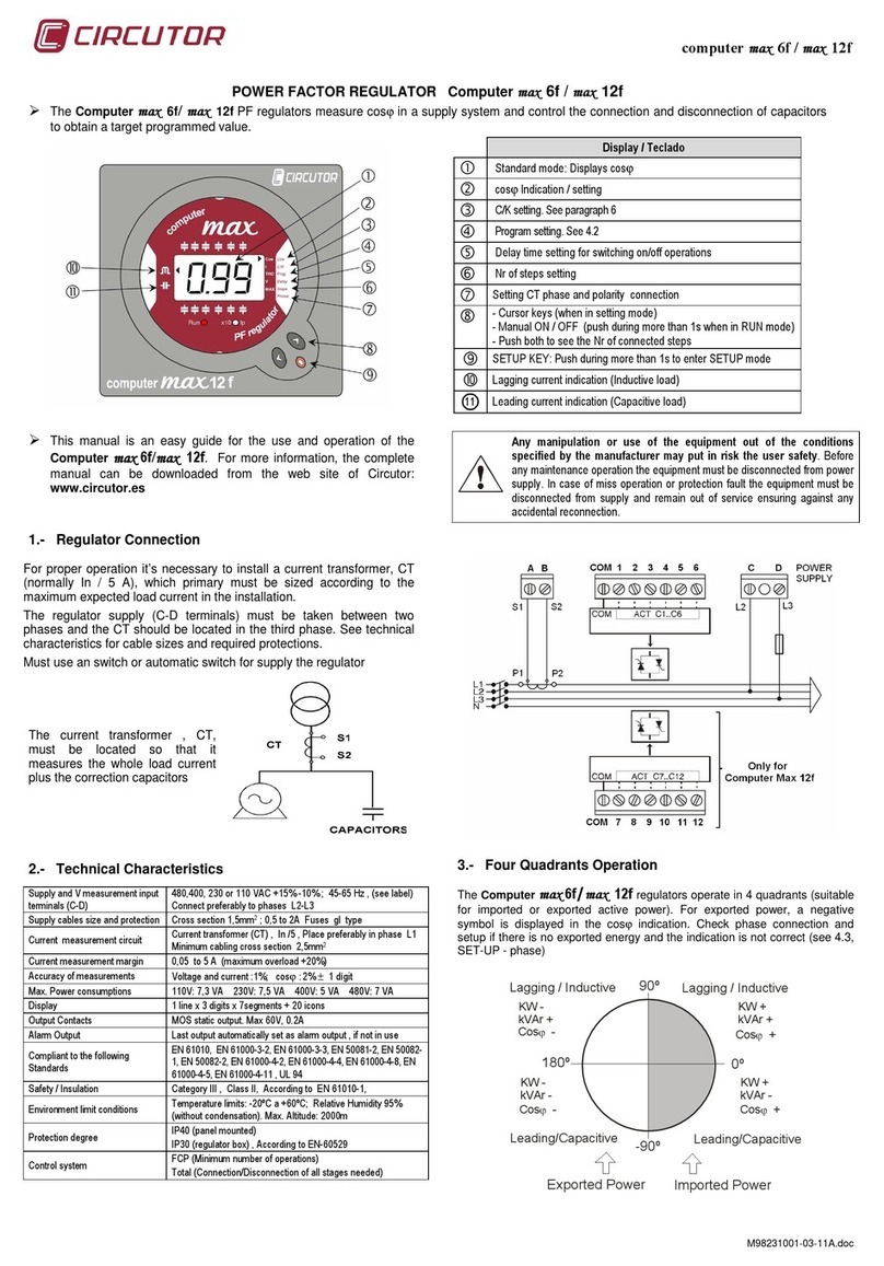
Circutor
Circutor max 12f User manual
Circutor
Circutor CDP series Supplement
Circutor
Circutor FastComp 12rt User manual
Circutor
Circutor Computer SMART III FAST 6 User manual
Circutor
Circutor CDP series Supplement
Circutor
Circutor CDP Supplement
Circutor
Circutor computer max 6f User manual
Circutor
Circutor Computer SMART III FAST 12Vdc User manual
Circutor
Circutor Computer SMART III 6 User manual

Circutor
Circutor CDP series Supplement
