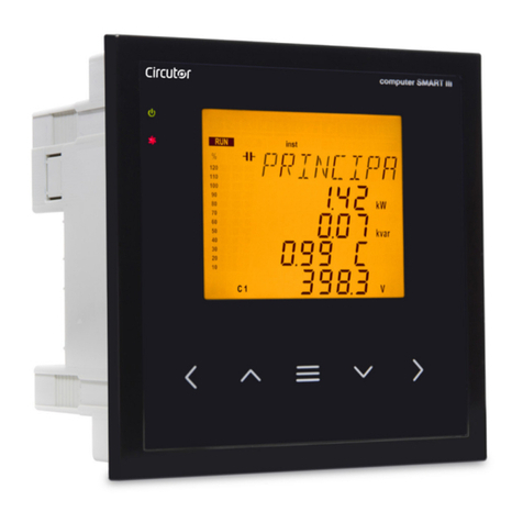
Circutor Computer SMART III FAST 6 User manual

INSTRUCTION MANUAL
(M021B01-03-21A)
REACTIVE ENERGY REGULATOR
Computer SMART III FAST
(Static operation)

2
Computer SMART III FAST
Instruction Manual

SAFETY PRECAUTIONS
DISCLAIMER
CIRCUTOR, SA reserves the right to make modifications to the device or the unit specifications set
out in this instruction manual without prior notice.
CIRCUTOR, SA on its web site, supplies its customers with the latest versions of the device specifica-
tions and the most updated manuals.
www.circutor.com
CIRCUTOR, recommends using the original cables and accessories that are supplied
with the device.
DANGER
Warns of a risk, which could result in personal injury or material damage.
ATTENTION
Indicates that special attention should be paid to a specific point.
Follow the warnings described in this manual with the symbols shown below.
If you must handle the unit for its installation, start-up or maintenance, the following should be
taken into consideration:
Incorrect handling or installation of the unit may result in injury to personnel as well as damage to the
unit. In particular, handling with voltages applied may result in electric shock, which may cause death
or serious injury to personnel. Defective installation or maintenance may also lead to the risk of fire.
Read the manual carefully prior to connecting the unit. Follow all installation and maintenance in-
structions throughout the unit’s working life. Pay special attention to the installation standards of the
National Electrical Code.
Refer to the instruction manual before using the unit
In this manual, if the instructions marked with this symbol are not respected or carried out correctly, it can result
in injury or damage to the unit and/or installations.
CIRCUTOR, SA reserves the right to modify features or the product manual without prior notification.
3
Instruction Manual
Computer SMART III FAST

CONTENTS
SAFETY PRECAUTIONS .........................................................................................................................................................3
DISCLAIMER ..........................................................................................................................................................................3
CONTENTS.............................................................................................................................................................................4
REVISION LOG .......................................................................................................................................................................6
SYMBOLS...............................................................................................................................................................................6
1. VERIFICATION UPON RECEPTION....................................................................................................................................7
2. PRODUCT DESCRIPTION .................................................................................................................................................7
3. DEVICE INSTALLATION....................................................................................................................................................9
3.1.- PRELIMINARY RECOMMENDATIONS ........................................................................................................................9
3.2.- INSTALLATION .........................................................................................................................................................9
3.3.- UNIT TERMINALS....................................................................................................................................................11
3.4.- CONNECTION DIAGRAM......................................................................................................................................... 12
3.4.1.- 3 VOLTAGES + NEUTRAL AND 3 CURRENTS, Computer SMART III FAST 6 model......................................... 12
3.4.2.- 3 VOLTAGES + NEUTRAL AND 3 CURRENTS, Computer SMART III FAST 12 model....................................... 13
3.4.3.- 3 VOLTAGES + NEUTRAL AND 1 CURRENT, COMPUTER SMART III FAST 6 model......................................... 14
3.4.4.- 3 VOLTAGES + NEUTRAL AND 1 CURRENT, Computer SMART III FAST 12 model.......................................... 15
3.4.5.- 2 VOLTAGES AND 1 CURRENT, Computer SMART III FAST 6 model. .............................................................. 16
3.4.6.- 2 VOLTAGES AND 1 CURRENT, Computer SMART III FAST 12 model.............................................................. 17
3.4.7. LEAKAGE CURRENT CONNECTION, I ............................................................................................................18
3.5.- STARTING UP THE UNIT ........................................................................................................................................ 19
4. OPERATION................................................................................................................................................................... 20
4.1.- DEFINITIONS.......................................................................................................................................................... 21
4.1.1 FOURQUADRANT REGULATOR......................................................................................................................... 21
4.1.2 STAGES AND STEPS........................................................................................................................................... 21
4.1.3 FCP SYSTEM FAST COMPUTERIZED PROGRAM. ............................................................................................ 21
4.1.4 REGULATION PROGRAM.................................................................................................................................... 21
4.1.5. PLUG AND PLAY. ...............................................................................................................................................22
4.1.6 CONNECTION TIME TON AND RECONNECTION TIME TREC. ........................................................................22
4.1.7 THD AND HARMONICS.......................................................................................................................................22
4.2.- MEASUREMENT PARAMETERS..............................................................................................................................23
4.2.1. CONNECTION TYPE: 3U.3C ...............................................................................................................................23
4.2.2. CONNECTION TYPE: 3U.1C...............................................................................................................................24
4.2.3. CONNECTION TYPE: 2U.1C...............................................................................................................................25
4.3.- KEY FUNCTIONS ....................................................................................................................................................26
4.4.- DISPLAY .................................................................................................................................................................28
4.4.1. STATUS OF THE CAPACITORS ............................................................................................................................29
4.4.2. STATUS OF THE UNIT........................................................................................................................................29
4.4.3. ANALOGUE BAR............................................................................................................................................... 30
4.4.4. OTHER SYMBOLS ON THE DISPLAY ................................................................................................................. 30
4.5.- LED INDICATORS.................................................................................................................................................... 31
4.6.- OPERATING STATES...............................................................................................................................................32
4.6.1. MEASUREMENT STATUS ...................................................................................................................................32
4.6.2. TEST STATUS .................................................................................................................................................... 51
4.7.- INPUTS...................................................................................................................................................................54
4.8.- OUTPUTS...............................................................................................................................................................54
4.9.- RS-485 COMMUNICATIONS...................................................................................................................................55
4.9.1. CONNECTIONS...................................................................................................................................................55
4.9.2. PROTOCOL ........................................................................................................................................................56
4.9.3. MODBUS MEMORY MAP ...................................................................................................................................57
4.9.4. EXAMPLE OF A MODBUS QUERY..................................................................................................................... 66
4.10.- CPC-NET COMMUNICATIONS.............................................................................................................................. 66
4.10.1. MODBUS CONTROL FRAME.............................................................................................................................67
5. CONFIGURATION .......................................................................................................................................................... 68
5.1.- PLUG&PLAY .......................................................................................................................................................... 69
5.2.- CURRENT TRANSFORMATION RATIO.....................................................................................................................72
5.3.- TARGET COS φ.......................................................................................................................................................73
5.4.- CONNECTION AND RECONNECTION TIME .............................................................................................................74
5.5.- CONNECTION TYPE................................................................................................................................................75
5.6.- PHASE CONNECTION.............................................................................................................................................75
4
Computer SMART III FAST
Instruction Manual

5.7.- NO. OF STAGES.......................................................................................................................................................77
5.8.- PROGRAM..............................................................................................................................................................78
5.9.- C/K FACTOR ..........................................................................................................................................................79
5.10.- ADVANCED SETUP ...............................................................................................................................................82
5.11.- VOLTAGE TRANSFORMATION RATIO .................................................................................................................... 83
5.12.- HYSTERESIS.........................................................................................................................................................84
5.13.- STATUS OF THE STAGES...................................................................................................................................... 85
5.14.- DISPLAY .............................................................................................................................................................. 86
5.15.- ANALOGUE BAR...................................................................................................................................................87
5.16.- FAN ..................................................................................................................................................................... 88
5.17.- UNDERVOLTAGE TRIP .......................................................................................................................................... 89
5.18.- RS-485 COMMUNICATIONS................................................................................................................................ 90
5.19.- CPC-NET COMMUNICATIONS............................................................................................................................... 91
5.20.- CLEAR..................................................................................................................................................................92
5.21.- ENABLING ALARMS .............................................................................................................................................93
5.22.- VOLTAGE ALARMS ...............................................................................................................................................94
5.23.- COS φLOW ALARM.............................................................................................................................................95
5.24.- COS φHIGH ALARM ........................................................................................................................................... 96
5.25.- VOLTAGE THD ALARM..........................................................................................................................................97
5.26.- CURRENT x I THD ALARM .................................................................................................................................. 98
5.27.- TEMPERATURE ALARM......................................................................................................................................100
5.28.- LEAKAGE CURRENT ALARM.............................................................................................................................. 101
5.29.- NO. OF OPERATIONS ALARM.............................................................................................................................102
5.30.- SIMULATION SCREEN........................................................................................................................................103
6. TECHNICAL FEATURES................................................................................................................................................104
7. MAINTENANCE AND TECHNICAL SERVICE.................................................................................................................. 107
8. WARRANTY.................................................................................................................................................................. 107
9. CE CERTIFICATE ..........................................................................................................................................................108
5
Instruction Manual
Computer SMART III FAST

REVISION LOG
Table 1: Revision log.
Date Revision Description
04/14 M021B01-03-14A Initial Version
05/16 M021B01-03-16A Changes in sections:
6.
03/17 M021B01-03-17A Changes in sections:
4.9.3.
03/18 M021B01-03-18A Changes in sections:
4.9.3.- 5.13.- 9
01/19 M021B01-03-19A Changes in sections:
4.9.3.
04/20 M021B01-03-20A Changes in sections:
2.- 4.4.- 4.5.- 4.9.3. - 5.13.
05/20 M021B01-03-20B Changes in sections:
4.9.3.- 5.16.
01/21 M021B01-03-21A Changes in sections:
4.6.1.- 4.9.3.- 5.3. - 5.12.- 5.23.- 5.24.
Note: Devices images are for illustrative purposes only and may differ from the actual device.
SYMBOLS
Table 2: Symbols
Symbol Description
In compliance with the relevant European directive.
Device covered by European directive 2012/19/EC. At the end of its useful life, do not
leave the unit in a household waste container. Follow local regulations on electronic
equipment recycling.
DC current
~AC current
6
Computer SMART III FAST
Instruction Manual

1.- VERIFICATION UPON RECEPTION
Check the following points when you receive the unit:
a) The unit meets the specifications described in your order.
b) The unit has not suffered any damage during transport.
c) Check the features shown on the label of the unit to make sure that they are suitable for the
type of grid to which the unit will be connected. (Voltage and power supply frequency, meas-
urement range, etc.)
d) Perform an external visual inspection of the unit prior to switching it on.
e) Check that it has been delivered with the following:
- An installation guide,
- Four retainers for rear attachment of the unit,
If any problems are detected upon reception, immediately contact the transport
company and/or the CIRCUTOR S.A. after-sales service.
2.- PRODUCT DESCRIPTION
The Computer SMART III FAST reactive energy regulator is a unit that measures the grid cosine and
regulates capacitor connection and disconnection in order to correct it. It also calculates and displays
the main electrical parameters of balanced or unbalanced single-phase and three-phase networks.
The measurement is taken in RMS, via four AC voltage inputs and three current inputs.
There are 2 versions of the unit, according to the number of output relays:
Computer SMART III FAST 6, with six optoMOS relay outputs.
Computer SMART III FAST 12, with twelve optoMOS relay outputs.
The unit features:
- 5 keys that can be used to browse the various screens and program the unit.
- 4 indicator LEDs: CPU, ALARM, FAN and KEY PRESSED.
- LCD display, amber backlit, 70x60.7 mm display for viewing all the parameters.
- 2 digital inputs, for selecting the target cosine (4 target cosines).
- 2 digital outputs and 1 relay output, fully programmable as alarms.
- 1 relay output, specific for the fan.
- 6 optoMOS relay outputs (Computer SMART FAST III 6 model) or 12 optoMOS relay outputs
7
Instruction Manual
Computer SMART III FAST

(Computer SMART FAST III 12 model) for regulating the cos φby means of capacitors.
- RS-485 communications, MODBUS RTU©.
- CPC-NET communications port.
8
Computer SMART III FAST
Instruction Manual

3.- DEVICE INSTALLATION
3.1.- PRELIMINARY RECOMMENDATIONS
In order to use the unit safely, it is critical that individuals who handle it follow the safety
measures set out in the standards of the country where it is being used, use the person-
al protective equipment necessary, and pay attention to the various warnings indicated
in this instruction manual.
The Computer SMART III FAST unit must be installed by authorised and qualified staff.
The power supply plug must be disconnected and measuring systems switched off before handling,
altering the connections or replacing the unit. It is dangerous to handle the unit while it is powered.
Also, it is critical to keep the cables in perfect condition in order to avoid accidents, personal injury and
damage to installations.
The manufacturer of the unit is not responsible for any damage resulting from failure by the user or
installer to heed the warnings and/or recommendations that appear in this manual, nor for damage
resulting from the use of products or accessories that did not come with the unit or that were made
by other manufacturers.
If an anomaly or malfunction is detected in the unit, do not use the unit to take any measurements.
Inspect the work area before taking any measurements. Do not take measurements in dangerous ar-
eas or where there is a risk of explosion.
Disconnect the unit from the power supply (unit and measuring system power supply)
before maintaining, repairing or handling the unit's connections.
Please contact the after-sales service if you suspect that there is an operational fault
in the unit.
3.2.- INSTALLATION
The Computer SMART III FAST regulator is connected to units that contain capacitors,
which remain charged after the voltage source is disconnected. Wait at least 5 min-
utes after the unit is disconnected before handling its internal components in order to
avoid the risk of electric shock.
Any manipulation or use of the unit other than that specified by the manufacturer
may compromise user safety.
Make sure that the units are correctly earthed before they are connected. A faulty earth connection
could lead to faulty operation and lead to a risk of electrical shock for the user or person handling the
unit.
Resonance can occur when the unit is connected with no load. In this case, the voltage harmonics can
be amplified, causing damage to the compensation unit and other units connected to the mains.
9
Instruction Manual
Computer SMART III FAST

The safe use of the COMPUTER SMART III FAST requires the persons installing or handling it to follow
the general safety measures of LV electrical installations, as well as the warnings indicated in this in-
struction manual.
The unit will be installed on a panel (138+1 x 138+1 mm panel drill hole, in compliance with DIN 43700).
All connections are inside the electric panel.
Terminals, opening roofs or removing elements can expose parts that are hazardous to
the touch while the unit is powered. Do not use the unit until it is fully installed.
The unit must be connected to a power circuit that is protected with gl (IEC 269) or M type fuses with
a rating of 0.5 to 2 A. It must be fitted with a circuit breaker or equivalent device for disconnecting the
unit from the power supply mains.
The power and voltage measurement circuits as well as the relay contact circuits must be connected
with cables that have a minimum cross-section of 1.5 mm2.
One or three external current transformers (CT) need to be installed in order to measure current. Usu-
ally, the transformation ratio of these CTs is In/5 A, where In is at least 1.5 times the total maximum
load current.
The secondary cables of the current transformers (CT) must have a minimum cross-section of 2.5 mm2.
For distances between the CTs and the unit of more than 25 m, this cross-section should be increased
by 1 mm2for every 10 m.
The current transformers (CT) must be installed at a point in the distribution panel which carries all the
current of the loads to be compensated as well as the current of the capacitors themselves ( Figure 1).
CORRECT INCORRECT
~
P1
P2
S1
S2
TC
LOAD CAPACITORS
The current transformers (CT) must
measure the combined current of
the capacitors plus the loads
If it does not work, make sure
that the CTs are not short-
circuited.
~
LOAD CAPACITORS
P1
P2
S1
S2
TC
If the CTs are connected in this
position, NONE OF THE CAPACITORS
WILL BE CONNECTED, even if there
are inductive loads.
The unit does not compensate.
~
LOAD CAPACITORS
P1
P2
S1
S2
TC
If the CTs are connected in this
position ALL THE CAPACITORS WILL
BE CONNECTED, but they will not be
disconnected if the load drops.
Risk of over-compensation in the
grid with no load.
Figure 1: Location of the current transformers
10
Computer SMART III FAST
Instruction Manual

3.3.- UNIT TERMINALS
Table 3:List of Computer SMART III FAST terminals.
Terminals of the top side of the unit
1: A1,Auxiliary power supply. 23: 8, Output 8 (Computer SMART III FAST 12 model)
2: A2,Auxiliary power supply. 24: 9, Output 9 (Computer SMART III FAST 12 model)
3: VL1, L1 voltage input 25: 10, Output 10 (Computer SMART III FAST 12 model)
4: VL2, L2 voltage input 26: 11, Output 11 (Computer SMART III FAST 12 model)
5: VL3,L3 voltage input 27: 12, Output 12 (Computer SMART III FAST 12 model)
6: VLN, Neutral voltage input 28: A(+), RS-485
7: S1,L1 current input 29: B(-), RS-485
8: S2, L1 current input 30: S, GND for RS-485
9: S1,L2 current input 31: 1, Digital input 1
10: S2, L2 current input 32: 2, Digital input 2
11: S1,L3 current input 33: C, Digital inputs common
12: S2, L3 current input 34: 1, Digital output 1
13: S1,Leakage current input 35: 2, Digital output 2
14: S2, Leakage current input 36: C, Digital outputs common
15: COM, Outputs common 37: Fan relay output
16: 1, Output 1 38: Fan relay output
17: 2, Output 2 39: NC, Alarm relay output
18: 3, Output 3 40: C, Alarm relay output
19: 4, Output 4 41: NO, Alarm relay output
20: 5, Output 5 42: A(+), CPC-NET
21: 6, Output 6 43: B(-), CPC-NET
22: 7, Output 7 (Computer SMART III FAST 12 model) 44: S, GND for CPC-NET
3
2
145 6 7 8 9 10 11 12 13
15
14
16
17
18
19
20
21
22
23
24
25
26
27
28 29 30 31 32 33 34 35 36 37 38 39 40 41
42
43
44
Figure 2: Computer SMART III FAST terminals.
11
Instruction Manual
Computer SMART III FAST

3.4.- CONNECTION DIAGRAM
3.4.1.- 3 voltages + Neutral and 3 currents, Computer SMART III FAST 6 model.
Connection type: 3U.3C
VLN IL2
S1
L1
L2
L3
N
VL1 VL2 VL3
S1 S2
P1 P2 S1 S2
P1 P2 S1 S2
P1 P2
S1 S1S2 S2 S2
IL3
IL1
A1 A2
Power Supply
COM 1 2 3 4 5 6
COM ACT C1...C6
Power Supply
Figure 3: 3 voltages + Neutral and 3 currents, Computer SMART III FAST 6 model.
Note: If the connection layout mentioned above is not respected, you must adjust the phase following
the procedure described in section "5.6.- PHASE CONNECTION”
Note: In this type of connection, the connection from Neutral to VLN is not mandatory.
12
Computer SMART III FAST
Instruction Manual

3.4.2.- 3 voltages + Neutral and 3 currents, Computer SMART III FAST 12 model.
Connection type: 3U.3C
VLN IL2
S1
L1
L2
L3
N
VL1 VL2 VL3
S1 S2
P1 P2 S1 S2
P1 P2 S1 S2
P1 P2
S1 S1S2 S2 S2
IL3
IL1
A1 A2
COM 1 2 3 4 5 6 7 8 9 10 11 12
COM ACT C1...C12
Power Supply
Power Supply
Figure 4: 3 voltages + Neutral and 3 currents, Computer SMART III FAST 12 model.
Note: If the connection layout mentioned above is not respected, you must adjust the phase following
the procedure described in section "5.6.- PHASE CONNECTION”
Note: In this type of connection, the connection from Neutral to VLN is not mandatory.
13
Instruction Manual
Computer SMART III FAST

3.4.3.- 3 voltages + Neutral and 1 current, Computer SMART III FAST 6 model.
Connection type: 3U.1C
VLN IL2
S1
L1
L2
L3
N
VL1 VL2 VL3
S1 S2
P1 P2
S1 S1S2 S2 S2
IL3
IL1
A1 A2
COM 1 2 3 4 5 6
COM ACT C1...C6
Power Supply
Power Supply
Figure 5: 3 voltages + Neutral and 1 current, Computer SMART III FAST 6 model.
Note: If the connection layout mentioned above is not respected, you must adjust the phase following
the procedure described in section "5.6.- PHASE CONNECTION”
Note: In this type of connection, the connection from Neutral to VLN is not mandatory.
Note: In this type of connection, the current transformer must be connected to the IL1 terminals.
14
Computer SMART III FAST
Instruction Manual

3.4.4.- 3 voltages + Neutral and 1 current, Computer SMART III FAST 12 model.
Connection type: 3U.1C
VLN IL2
S1
L1
L2
L3
N
VL1 VL2 VL3
S1 S2
P1 P2
S1 S1S2 S2 S2
IL3
IL1
A1 A2
Power Supply
COM 1 2 3 4 5 6 7 8 9 10 11 12
COM ACT C1...C12
Power Supply
Figure 6: 3 voltages + Neutral and 1 current, Computer SMART III FAST 12 model.
Note: If the connection layout mentioned above is not respected, you must adjust the phase following
the procedure described in section "5.6.- PHASE CONNECTION”
Note: In this type of connection, the connection from Neutral to VLN is not mandatory.
Note: In this type of connection, the current transformer must be connected to the IL1 terminals.
15
Instruction Manual
Computer SMART III FAST

3.4.5.- 2 voltages and 1 current, Computer SMART III FAST 6 model.
Connection type: 2U.1C
VLN IL2
S1
L1
L2
L3
N
VL1 VL2 VL3
S1 S2
P1 P2
S1 S1S2 S2 S2
IL3
IL1
A1 A2
Power Supply
COM 1 2 3 4 5 6
COM ACT C1...C6
Power Supply
Figure 7: 2 voltages and 1 current, Computer SMART III FAST 6 model.
Note: If the connection layout mentioned above is not respected, you must adjust the phase following
the procedure described in section "5.6.- PHASE CONNECTION”
Note: In this type of connection, the Neutral connection is not necessary.
Note: In this type of connection, the current transformer must be connected to the IL1 terminals, and
the two voltages must be connected to VL1 and VL2.
16
Computer SMART III FAST
Instruction Manual

3.4.6.- 2 voltages and 1 current, Computer SMART III FAST 12 model.
Connection type: 2U.1C
VLN IL2
S1
L1
L2
L3
N
VL1 VL2 VL3
S1 S2
P1 P2
S1 S1S2 S2 S2
IL3
IL1
A1 A2
COM 1 2 3 4 5 6 7 8 9 10 11 12
COM ACT C1...C12
Power Supply
Power Supply
Figure 8: 2 voltages and 1 current, Computer SMART III FAST 12 model.
Note: If the connection layout mentioned above is not respected, you must adjust the phase following
the procedure described in section "5.6.- PHASE CONNECTION”.
Note: In this type of connection, the Neutral connection is not necessary.
Note: In this type of connection, the current transformer must be connected to the IL1 terminals, and
the two voltages must be connected to VL1 and VL2.
17
Instruction Manual
Computer SMART III FAST

3.4.7.- Leakage current connection, IΔ
To measure the leakage current, an earth leakage transformer must be used, such as WGS.
The leakage current transformer must be connected such as to measure the current of the capacitor
bank. This will detect any leakage in the capacitors of the capacitor bank.
~
TC
LOAD CAPACITORS
S1 S2
P1 P2
I∆
S1
S1
S2
S2
IL1, IL2, IL3
Figure 9: Connection of the leakage current transformer (IΔ).
Note: The earth leakage transformer must have a ratio of 500 turns. The maximum leakage current
that the unit can measure correctly is 1.5A AC, even though the maximum input is 5A AC via the earth
leakage transformer.
Do not operate the leakage current transformer with the Computer SMART III FAST
powered on.
18
Computer SMART III FAST
Instruction Manual

3.5.- STARTING UP THE UNIT
Once the Computer SMART III FAST is powered on, the following screen appears on the display, Figure
10, which shows the name of the unit, the version and the model.
Figure 10: Computer SMART III FAST home screen.
After a few seconds, the main measurement screen appears.
19
Instruction Manual
Computer SMART III FAST

4.- OPERATION
The Computer SMART III FAST is a reactive energy regulator unit that measures the cos φof the grid
and that regulates the connection and disconnection of capacitors in order to correct it.
The control is carried out in the four quadrants, Figure 11.
Inductive Inductive
Capacitive Capacitive
Inductive Inductive
Capacitive Capacitive
Generated
Power
Consumed
Power
Consumed
Power
Generated
Power
Figure 11: Measurement and Compensation in the four quadrants.
In addition to the basic functions of any regulator the Computer SMART III FAST:
Performs the functions of a network analyzer, measuring and displaying multiple parameters.
Has a Plug&Play function for automatic configuration of the unit.
Has an AutoTest and manual Test function for testing the status of the capacitor bank capacitors.
Has an FCP system which minimises the number of capacitor connections and disconnections.
Supports step forcing.
Can work with various connection types.
Measures leakage current with the option of associating an alarm and conducting a search for and
cancelling the faulty capacitor.
Has multiple alarms for warning of possible faults, whether in the capacitor bank or in the installa-
tion.
20
Computer SMART III FAST
Instruction Manual
This manual suits for next models
1
Table of contents
Other Circutor Controllers manuals
Circutor
Circutor Computer SMART III FAST 12Vdc User manual
Circutor
Circutor computer max 6f User manual
Circutor
Circutor max 12f User manual
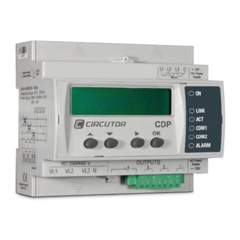
Circutor
Circutor CDP series Supplement
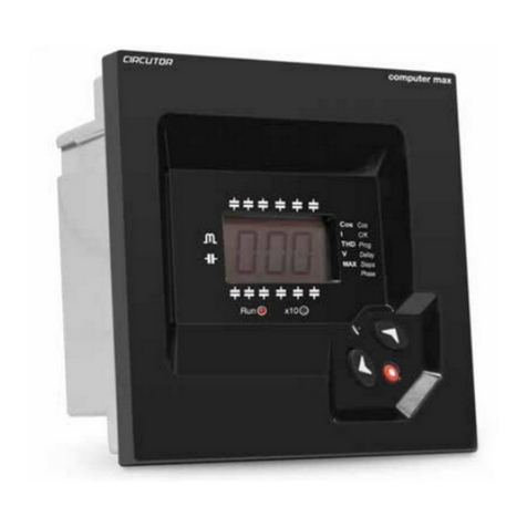
Circutor
Circutor computer MAX 6 User manual

Circutor
Circutor CDP series Supplement
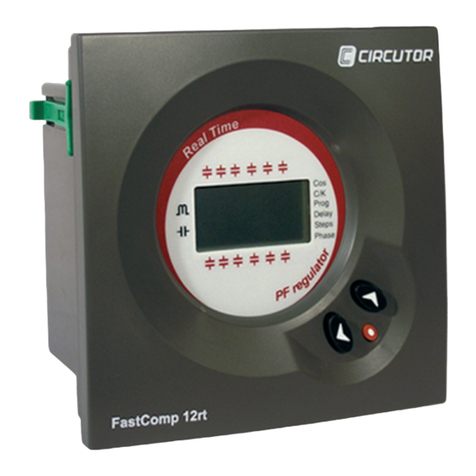
Circutor
Circutor FastComp 12rt User manual
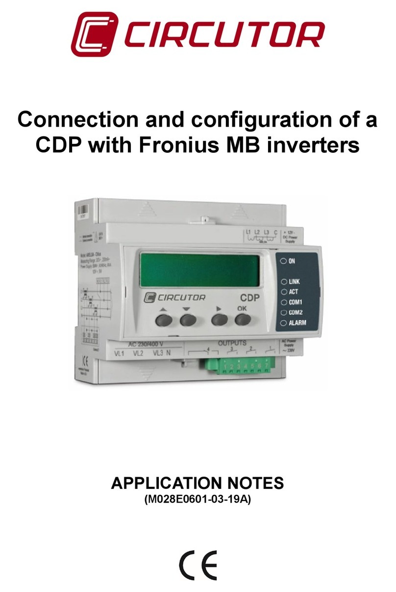
Circutor
Circutor CDP Supplement

Circutor
Circutor CDP series Supplement
Circutor
Circutor Computer SMART III 6 User manual
