manuals.online logo
Brands
  1. Home
  2. •
  3. Brands
  4. •
  5. KMC Controls
  6. •
  7. Controllers
  8. •
  9. KMC Controls BAC-7003 User manual

KMC Controls BAC-7003 User manual

BAC-7003 and BAC-7053 VAV controllers 1 Installation Guide
BACnet VAV controllers
BAC-7003 and BAC-7053
Installation Guide
These are brief instructions for installing a BAC‑7000
series VAV controller. For more detailed instructions,
review the document Installation, Operation, and
Application Guide for BAC-7000 Series VAV Controllers.
Mounting
Refer to “Illustration 1—Mounting the BAC‑7000
VAV controllers” when mounting the controllers on
a VAV terminal unit.
Set the rotation limits
Before mounting the controller, set the rotational
limits with the two supplied stop pins. These seings
limit the shaft rotation in the clockwise (CW) and
counterclockwise (CCW) directions.
Drive hub
Gear clutch button
Anti rotation
bracket
Illustration 1—Mounting the BAC-7000 VAV controllers
Notch and
lock tab
www.kmccontrols.com/ag/bac‑7003
Mount the controller
1. Back the set screws out of the drive hub until the
shaft can t through the collar.
2. Place the controller on the damper shaft in the
approximate nal position.
3. Position the anti‑rotation bracket and fasten it
using #8 or #10 self‑tapping screws. Verify the
notch in the bracket securely engages the lock tab
on the controller.
4. Manually position the VAV damper in the fully
open position.
5. Press the gear clutch buon and rotate the
drive hub in the same direction that opened the
damper. Turn the hub until it reaches a rotation
limit.
6. Tighten the two set screws in the drive hub to
approximately 50–inch pounds (5.65 N•m) to
lock the hub to the shaft.
BAC-7003 and BAC-7053 VAV controllers 2 Installation Guide
1
+B-A SI1I2I3
GND GND O1 T2 RTN2 R3 RTN3
Wiring
Connecting outputs
The BAC‑7003 and BAC‑7053 include one single‑
stage triac, one relay and one universal output.
When connecting loads to the triac or relay output,
use only the terminal marked RTN associated with
the triac or relay for the 24‑volt circuit.
Output O1—This output is a universal output that
can be programmed as either an analog object for
modulating reheat. The universal output is rated for
0‑10 volt DC loads. Use the GND terminal on the
input connector block for the ground.
Output T2 —This is a triac output programmed to
switch 24‑volt reheat circuits. The output is rated
for 24 volt, 1 ampere loads, and switches on zero
crossing. Use the RTN2 terminal for the T2 load.
Output R3—This is a normally open relay contact
programmed to control a 24‑volt fan starting
circuit. The relay contacts are rated for 24‑volts at 2
amperes. Use RTN3 for the R3 load.
+B-A S
Airflow inputs
NetSensor
input
Power terminals
Input
terminals
MS/TP
terminals
Output terminals
Ready and
Communication lights
All input, output, power and network connection
points are located beneath the access cover. Remove
the two screws that secure this cover to remove the
cover.
The controller is supplied with a removable conduit
plate with two 0.5 inch threaded conduit couplings.
If conduit connections are used, note the following:
 The conduit plate may be removed by removing
the two screws that secure the access cover
and removing the cover. Connect the required
conduit and replace the plate in the controller
housing.
 The plugs may also be sliced to allow wiring to
enter the controller with a minimum of outside
contaminates.
Connecting inputs
The BAC‑7000 VAV controllers have three universal
inputs. Each input is congured to support the
standard application programs in the controller.
By using the internal termination resistors, either
passive or active devices may be connected to the
inputs.
Note: If a NetSensor is connected to the controller,
the standard application programming will use the
temperature and setpoint from the NetSensor and
not from devices connected to Input I1 and Input I2.
KMC supplied Control Basic programs assigns
inputs to the following functions.
Input I1—Connect to a space temperature sensor
input such as the 10 kΩ thermistor in an STE‑6000
series sensor.
Illustration 2—BAC-7000 VAV controller with access cover removed
Input I2—This is a setpoint input which is typically
the 0‑10 kΩ potentiometer STE‑6000 series sensor.
Input I3—This is an optional input congured for a
10 kΩ. discharge air temperature sensor.
Seing the internal pull–up resistors—For passive
input signals, such as thermistors or switch contacts,
set the input termination switch to the On position.
Ground terminals—Use the GND terminal located
next to the input terminals for the input ground
connection.
Power jumper
Input termination
EOL switches
Network
disconnect On
On
O1 T2 RTN2 R3 RTN3
BAC-7003 and BAC-7053 VAV controllers 3 Installation Guide
Connecting to a NetSensor
The Network RJ–12 connector provides a
connection port to a NetSensor model KMD‑1161.
Link the controller to a NetSensor with a KMC
Controls approved cable up to 75 feet long. See the
installation guide supplied with the NetSensor for
complete NetSensor installation instructions.
Connecting an airflow sensor
An airow sensor is incorporated as one of the
inputs to the controller. Remove the plugs and
connect the tubing from the pitot assembly to the
airow sensor inputs above the drive hub.
Mount the controller close enough to the pitot tubes
to keep the tubing length to be less than 24 inches
between the controller’s inputs and the tubes.
Connecting to an MS/TP network
BAC‑7000 series VAV controllers BACnet MS/
TP compliant controllers. Connect them only
to a BACnet MS/TP network. Use the following
principles when connecting a controller to an MS/TP
network:
 Connect no more than 128 addressable BACnet
devices to one MS/TP network. The devices can
be any mix of controllers or routers.
 To prevent network trac bolenecks, limit the
MS/TP network size to 60 controllers.
 Use 18 gauge, twisted pair, shielded cable with
capacitance of no more than 50 picofarads per
foot for all network wiring. Belden cable model
#82760 meets the cable requirements.
 Connect the ‑A terminal in parallel with all other
‑ terminals.
 Connect the +B terminal in parallel with all other
+ terminals.
 Connect the shields of the cable together at each
controller. For KMC BACnet controllers use the
S terminal.
 Connect the shield to an earth ground at one end
only.
 Connect a KMD–5575 BACnet MS/TP repeater
between every 32 MS/TP devices or if the cable
length will exceed 4000 feet (1220 meters). Use
no more than four repeaters per MS/TP network.
 Place a KMD–5567 surge suppressor in the cable
where it exits from a building.
 On the controllers at the physical ends of the
EIA‑485 wiring segment, set the end‑of‑line
termination to On using the EOL switches.
See Application Note AN0404A, Planning BACnet
Networks for additional information about installing
controllers.
Connecting power
The controllers require an external, 24 volt, AC
power source. Use the following guidelines when
choosing and wiring transformers.
 Use a KMC Controls Class–2 transformer of
the appropriate size to supply power to the
controllers.
 KMC Controls recommends powering only one
controller from each transformer.
 Do not run 24 volt, AC power from within an
enclosure to external controllers.
Connect the 24 volt AC power supply to the
power terminal block on the lower right side of
the controller near the power jumper. Connect the
ground side of the transformer to the – terminal
and the AC phase to the ~ (phase) terminal. Power
is applied to the controller when the transformer
is connected to power and the power jumper is in
place.
S
+B
-A
S
+B
-A
S
+B
-A
Illustration 3—MS/TP network wiring
Set the EOL
switches to On for
these controllers.
BAC-7003 and BAC-7053 VAV controllers 4
KMC Controls, Inc.
19476 Industrial Drive
New Paris, IN 46553
574.831.5250
www.kmccontrols.com
[email protected]
Accessories and replacement parts
Replacement parts
HMO‑4531 Non rotation bracket‑ KMD‑
7001
HPO‑0054 Bulbs
HPO‑0063 2‑pin KMD jumper (5/Pkg)
Shaft adaptor
HFO‑0011 3/8 inch (9.5 mm) shaft
adaptor
Airflow sensors
Order one of the following for installation on VAV
units without airow sensor pickup tubes.
SSS‑1012 3‑5/32 in. length (80 mm)
SSS‑1013 5‑13/32 in. length (137 mm)
SSS‑1014 7‑21‑32 in. length (195 mm)
SSS‑1015 9‑29/32 in. length (252 mm)
Power transformer
XEE‑6111‑40 Single‑hub 120 volt
transformer
XEE‑6112‑40 Dual‑hub 120 volt transformer
Important Notices
The material in this document is for information
purposes only. The contents and the product it
describes are subject to change without notice.
KMC Controls, Inc. makes no representations or
warranties with respect to this document. In no event
shall KMC Controls, Inc. be liable for any damages,
direct or incidental, arising out of or related to the
use of this document.
Operation
Once congured, programmed and powered, the
controller requires very lile user intervention.
Configuration and set up
The BAC‑7000 series VAV controllers are supplied
with standard applications for single duct VAV
termal units. Final setup requires BACstage,
TotalControl or another BTL listed BACnet Operator
Workstation. Custom programming requires
BACstage or TotalControl.
Balancing with a NetSensor
The BAC‑7000 series VAV controllers include
internal programming to use a KMD‑1161 NetSensor
as a technicians balancing tool. This procedure is
described in the the document Installation, Operation,
and Application Guide for BAC-7000 Series VAV
Controllers.
Maintenance
BAC‑7000 series VAV controllers require no routine
maintenance. If necessary, clean with a damp cloth
and mild soap.
907-019-53H

This manual suits for next models

1

Other KMC Controls Controllers manuals
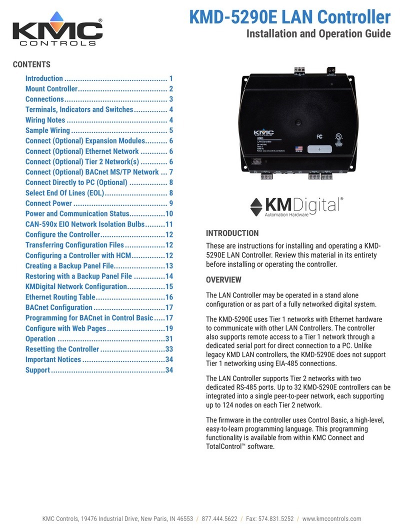
KMC Controls KMD-7001 Original operating instructions

KMC Controls

KMC Controls KMD-7001 Original operating instructions

KMC Controls BAC-9001CE User manual

KMC Controls

KMC Controls BAC-9001CE User manual

KMC Controls FlexStat BAC-12 63 Series User manual

KMC Controls

KMC Controls FlexStat BAC-12 63 Series User manual

KMC Controls CSP-4702 User manual

KMC Controls

KMC Controls CSP-4702 User manual

KMC Controls BAC-7401 Operating instructions

KMC Controls

KMC Controls BAC-7401 Operating instructions

KMC Controls KMD-5831 Original operating instructions

KMC Controls

KMC Controls KMD-5831 Original operating instructions

KMC Controls AppStat User manual

KMC Controls

KMC Controls AppStat User manual

KMC Controls CTE-3017 User manual

KMC Controls

KMC Controls CTE-3017 User manual

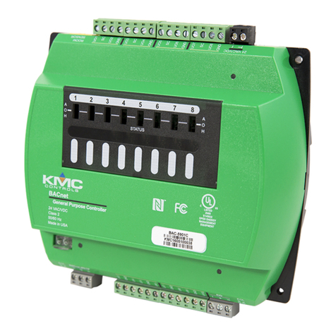
KMC Controls KMDigital KMD-5290E Operating instructions
KMC Controls

KMC Controls KMDigital KMD-5290E Operating instructions

KMC Controls CEE-3009 User manual

KMC Controls

KMC Controls CEE-3009 User manual

KMC Controls MEP-1500 Series User manual

KMC Controls

KMC Controls MEP-1500 Series User manual

KMC Controls CSC 3000 Series User guide

KMC Controls

KMC Controls CSC 3000 Series User guide

KMC Controls SimplyVAV BAC-8205 User manual

KMC Controls

KMC Controls SimplyVAV BAC-8205 User manual

KMC Controls FlexStat BAC-120063CW-ZEC Operator's manual

KMC Controls

KMC Controls FlexStat BAC-120063CW-ZEC Operator's manual

KMC Controls MCP-1020 Series User manual

KMC Controls

KMC Controls MCP-1020 Series User manual

KMC Controls MEP-7 Series User guide

KMC Controls

KMC Controls MEP-7 Series User guide

KMC Controls MCP-1160 Series User manual

KMC Controls

KMC Controls MCP-1160 Series User manual

KMC Controls CSC 3000 Series User guide

KMC Controls

KMC Controls CSC 3000 Series User guide

KMC Controls SimplyVAV BAC-8001 User guide

KMC Controls

KMC Controls SimplyVAV BAC-8001 User guide

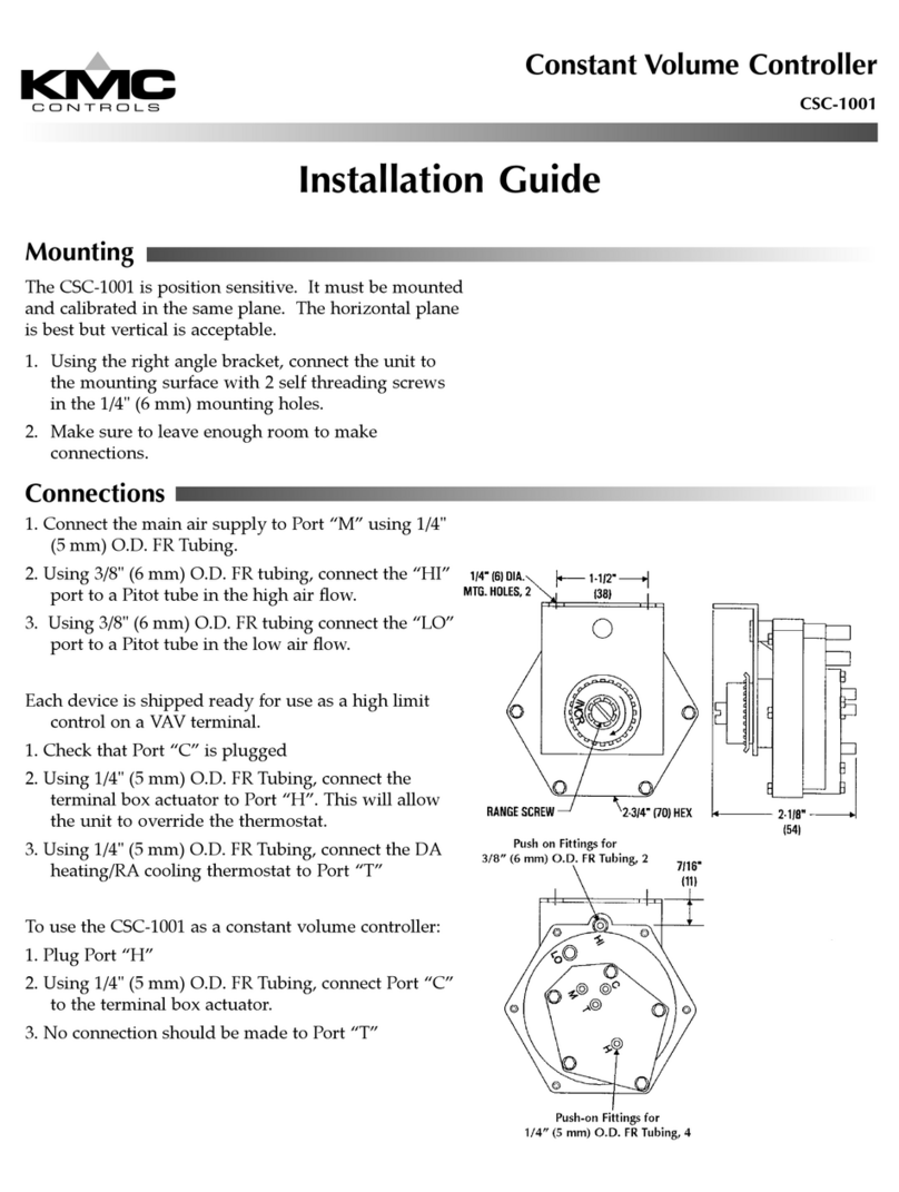
KMC Controls KMD-5205 Operating instructions
KMC Controls

KMC Controls KMD-5205 Operating instructions

KMC Controls MEP-4201 User manual

KMC Controls

KMC Controls MEP-4201 User manual

KMC Controls SimplyVAV BAC-8001 User manual

KMC Controls

KMC Controls SimplyVAV BAC-8001 User manual

KMC Controls BAC-9300 Series User manual

KMC Controls

KMC Controls BAC-9300 Series User manual

KMC Controls BAC-5901C-AFMS User manual

KMC Controls

KMC Controls BAC-5901C-AFMS User manual

Popular Controllers manuals by other brands

alphainnoTec Luxtronik operating instructions

alphainnoTec

alphainnoTec Luxtronik operating instructions

digitalview 41710002X-3 instructions

digitalview

digitalview 41710002X-3 instructions

FeiYu Tech 41AP quick start guide

FeiYu Tech

FeiYu Tech 41AP quick start guide

Kieback&Peter FBR5 manual

Kieback&Peter

Kieback&Peter FBR5 manual

Oriental motor CRD514-KD Information

Oriental motor

Oriental motor CRD514-KD Information

Icom IP1000C quick start guide

Icom

Icom IP1000C quick start guide

Multitech CommPlete MR9600-100 user guide

Multitech

Multitech CommPlete MR9600-100 user guide

PowerWalker AVR 1200 quick start guide

PowerWalker

PowerWalker AVR 1200 quick start guide

Tolomatic BCS10 Quick start quide

Tolomatic

Tolomatic BCS10 Quick start quide

Delta VFD-L user manual

Delta

Delta VFD-L user manual

AutomationDirect NITRA PNEUMATICS Setup instructions

AutomationDirect

AutomationDirect NITRA PNEUMATICS Setup instructions

Casa Fan ST4-150 II Mounting and operating manual

Casa Fan

Casa Fan ST4-150 II Mounting and operating manual

Life Smart LS143 quick start guide

Life Smart

Life Smart LS143 quick start guide

COLORKINETICS Data Enabler IntelliPower installation instructions

COLORKINETICS

COLORKINETICS Data Enabler IntelliPower installation instructions

Control Technologies 2646 MultiPro installation guide

Control Technologies

Control Technologies 2646 MultiPro installation guide

Delta DAC-1600 installation guide

Delta

Delta DAC-1600 installation guide

WorkPro Nemesis 136 User instructions

WorkPro

WorkPro Nemesis 136 User instructions

Iron logic Matrix III NET user manual

Iron logic

Iron logic Matrix III NET user manual

manuals.online logo
manuals.online logoBrands
  • About & Mission
  • Contact us
  • Privacy Policy
  • Terms and Conditions

Copyright 2025 Manuals.Online. All Rights Reserved.