LM25-M
M98250301-03-13A-LM25.docx
1.- DESCRIPTION
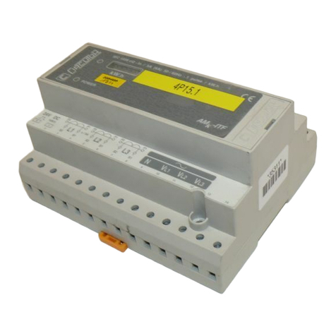
LM25-M is a concentrator with 25 digital inputs,
designed to centralize the status of up to 25 logical
signals, or the number of impulses received at each
of the inputs. In addition, the unit has the capacity to
time the active or inactive status of an input.
This document is the user and operation manual of the LM25-
M device. If misplaced, the manual may be downloaded from
CIRCUTOR's web site:
www.circutor.com
Disconnect the device from
all power supply
sources before undertaking any form of
maintenance, modification of connections,
repairs, etc. If you suspect any operational faults
in the unit or in its protection system, remove the device from
its power supply and leave it out of service. The design of the
unit makes it easy to replace in the event of a fault.
If the unit is not operated according to the manufacturer's
specifications, the unit's guaranteed degree of protection may
be compromised.
The vast majority of energy, water and gas meters
have an impulse output proportional to the unit
consumed by the installation. LM25-M is a centralizer
unit that features twenty-five digital inputs activated
by potential-free contact whose main function is to
read the impulses coming from those meters.
In addition, the unit has the capacity to time the
activation/deactivation of each of its inputs,
depending on how the unit's configuration is
programmed. Thus, it is a timer concentrator,
depending on the status of each of its inputs (0/1).
2.- INSTALLATION
The unit is installed in DIN rail 46277 (EN 50022). All
connections remain inside the electrical panel.
Take into account that when the unit is
connected, the terminals may be hazardous
to the touch, and opening the covers or
removing elements may provide access to
parts that are dangerous to the touch. Do not use the unit until
it is fully installed.
The unit must be connected to a power circuit
protected with type gl fuses, in compliance with IEC
269, or type M, with values ranging from 0.5 to 1A. It
must be fitted with a circuit breaker switch or
equivalent device in order to be able to disconnect
the unit from the mains power supply. The power
supply cable must have a cross-section of at least 1
mm2.
2.1.- Terminals
RS-485 communication connection
N L Power supply terminals
3.- START-UP
One or several LM25-M centralizers can be
connected to a computer or PLC. This system makes
it possible to centralise the data in a single log point,
in addition to the normal operation of each unit
(PowerStudio® platform). The LM25-M has an RS-
485 serial communication output. If more than one
device is connected to a serial communication bus,
each one must be assigned a distinct peripheral
number or address (from 01 to 254), with a maximum
of 32 units per communication bus, so that the
central computer sends the queries from the various
requested logs to these addresses.
4.- CONFIGURATION PARAMETERS
The LM25-M has a RS-485 communication port for
reading and writing to the 25 internal meters through
a management application; to do so, it uses the
Modbus/RTU communications protocol.
The unit has functions for reading and resetting the
various internal meters and functions for reading the
timers of each of the digital inputs. The unit has write
variables for changing the communication
parameters (peripheral, speed, etc.).
4.1.- Slave address configuration
The unit comes with peripheral number 95 by default
(5F in hexadecimal). The Modbus address
modification write command can be used to assign
any other address (a maximum of FE in
hexadecimal, equivalent to peripheral 254 in
decimal).
4.2.- Communications configuration
The unit's communication configuration is by default
19200, 8, N, 1. It is possible to assign this speed
using Modbus RTU write commands.
Peripheral Configuration / Speed Writing
0200
Modbus Address
From 0001 to 00FF (Hex)
01 Decimal
to 254 Decimal
0201 Bauds
RS485 bus speed
0001
0002
0003
9,600 bauds
19,200 bauds
38,400 bauds
0202 Parity
0001
Odd
0203 Stop bits
For example:
Request to modify the Modbus address and speed. Tx: 5F 10
0200 0004 08 0001 0001 0000 0001CRC
(peripheral 01, 9600, N, 1).
4.3.- Default configuration
If you do not know or remember the slave number or
the other communication parameters, you can
restore the unit's default values using the following
procedure:
- Disconnect the unit's power supply.
- Press and hold the front-panel button while
reconnecting the device's auxiliary power supply.
- Hold the button down for five seconds with the
power supply connected. Once the default values
have been programmed, the Rx and Tx LEDs will
flash, indicating that the operation was successful.
- Then release the button.
4.4.- Read and write functions
The Modbus read function for reading internal logs is
03 and 04 Hex and for writing it is 06 and 10 Hex.
Writing of one log or several logs
4.5.- Logic status of the inputs
When requesting Modbus instructions, the device
returns the information on the logic status of each of
the digital inputs.
Digital Input Status Reading
0000
Bits 15 to 0
Input status 16 to 1
0001
Bits 8 to 0
Input status 25 to 17
For example:
Request to read the logic status of digital inputs Tx: 5F 04
0000 0001 CRC (request for the status of inputs 1 to 16).
4.6.- Impulse width configuration (ms)
LM25-M enables configuration of the minimum
impulse width (minimum and default time is 10 ms),
to increase the impulses in a unit. The minimum
time between two successive impulses at the same
input must be 1 ms. This represents a maximum
sampling frequency at each of the inputs of 90 Hz.
The millisecond value is the same for all the digital
inputs.
Impulse width configuration (ms)
00F0
Minimum time: 10
Maximum time: 500
For example:
Request to write the minimum time of the impulse at 50 ms.
Tx: 5F 10 00F0 0001 02 0032 CRC
4.7.- Impulse value of the inputs
Using the Modbus address reading function indicated
in the table above, you can get the total value of the
impulses recorded at each of the digital inputs.
Reading of impulse values - Inputs 1 to 25
0000 0000 … FFFF FFFF (Hex)
0000 0000 … FFFF FFFF (Hex)
0000 0000 … FFFF FFFF (Hex)
0000 0000 … FFFF FFFF (Hex)
0000 0000 … FFFF FFFF (Hex)
0000 0000 … FFFF FFFF (Hex)
0000 0000 … FFFF FFFF (Hex)
For example:
Request to read the impulses received by meter 1. Tx: 5F 04
0080 0002 CRC
4.8.- Timebase of the timers
Considering each meter's time, keep in mind that the
timebase is the same for all inputs, with a maximum
value of 4,294,967,296 units, and once this value is
exceeded the timer will reset to zero.
Keep in mind the scale being used for each timer,
which can vary between: seconds, tenths of seconds,
hundredths of seconds and milliseconds. This scale
is the same for all the digital inputs.
Timebase of the digital inputs
00F5 Timebase Selection
0001
0002
0.1 s
0.01 s
For example:
Request to write the timebase of the 25 meters. Tx: 5F 10 00F5
0001 02 0001 CRC (Timebase 0.1 sec.).
4.9.- Configuration of timer status
LM25-M allows the total time to be measured, or the
time of the most recent ON / OFF operation detected
by the digital input.
This configuration can be applied individually to each
of the twenty-five digital inputs, according to the
needs of the installation.
Configuration of the time log mode
00F6
1 = Most recent impulse
Input status 16 to 1
00F7
1 = Most recent impulse
Input status 25 to 17
For example:
Write request for the configuration of the time log mode for
each of the digital inputs. Tx: 5F 10 00F6 0002 04 01F0 7C1F
CRC
Input status of inputs 25 to 1 (considering 25):
00000001111100000111110000011111 = 01F0 7C1F (Hex)
The activation of the timers can be configured using
an open or closed input, and every one of the unit's
inputs is configurable.
Timer status for ON and OFF positions
00F1
ON = Bit at 0
OFF = Bit at 1
Bits 15 to 0
Input status 16 to 1
00F2
ON = Bit at 0
OFF = Bit at 1
Bits 8 to 0
Input status 25 to 17
For example:
Write request for the configuration of the timer status for each
of the digital inputs. Tx: 5F 10 00F6 0002 04 01F0 7C1F CRC
Input status of inputs 32 to 1 (considering 25):
00000001111100000111110000011111 = 01F0 7C1F (Hex)
4.10.- Time value of the inputs
The reading of the logged time value (depending on
the timebase) at each of the digital inputs is obtained
from the reading of the following Modbus logs:
Reading of time values - Inputs 1 to 25
0000 0000 … FFFF FFFF (Hex)
0000 0000 … FFFF FFFF (Hex)
0000 0000 … FFFF FFFF (Hex)
0000 0000 … FFFF FFFF (Hex)
0000 0000 … FFFF FFFF (Hex)
0000 0000 … FFFF FFFF (Hex)
For example:
Request to read the time logged at input 1. Tx: 5F 04 00B2
0002 CRC


