Jinko JK625 User manual

User’s Guide
HANDHELD BATTERY INTERNAL RESISTANCE TESTER
Changzhou Jinailian Electronic Technology Co., Ltd
No.C3,Building 22,New Impetus Pioneering Center, No.1,Qingyang North Road,Tianning
District,Changzhou,Jiangsu,CN
TEL: 0086-519-85563477 FAX: 0086-519-85565067
https://jinailian.en.alibaba.com www.jk17.com www.jaldz.com
JK625/JK625L

1/24
Statement
In accordance with international copyright law, the content of this article may not be reproduced in
any form without the prior permission and written consent of the state-wide JinAilian Electronic
Technology Co., Ltd.
Security Information
WARNING DANGER: To avoid possible electric shock and personal safety, follow
these guidelines.
Disclaimer
Before you start using the instrument, please read the following safety information carefully. Jinko
Instruments will not bear any responsibility for personal safety and property damage caused by the
user's failure to comply with the following terms.
Instrument grounding
To prevent the risk of electric shock, connect the power ground wire.
Do not use the instrument in explosive atmospheres
Do not use the instrument in a flammable or explosive atmosphere, steam or dusty environment.
Using any electronic device in such an environment is a personal risk.
Do not open the instrument case
Non-professional maintenance personnel must not open the instrument case in an attempt to repair
the instrument. There is still a clean charge that has not been discharged for a period of time after the
instrument has been switched off, which may cause an electric shock hazard to personnel.
Do not use the instrument in a manner not specified in this manual
Outside the range, the protection provided by the instrument will be invalidated.
Warning: Do not apply DC voltage or current to the test terminal, otherwise it will damage
the instrument.
Safety sign: equipment is protected by double insulation or reinforced insulation
Waste Electrical and Electronic Equipment (WEEE) Directive 2002/96 / EC

2/24
Do not throw away in the trash
CERTIFICATION, LIMITED WARRANTY, & LIMITATION OF LIABILITY
Jinailian Electronic Technology Co., Ltd (shortened form Jinailian)certifies that
this product met its published specifications at the time of shipment from the factory.
Jinailian further certifies that its calibration measurements are traceable to the People’s
Republic of China National Institute of Standards and Technology, to the extent
allowed by the Institution’s calibration facility or by the calibration facilities of other
International Standards Organization members.
This Jinailian instrument product is warranted against defects in material and
workmanship for a period corresponding to the individual warranty periods of its
component products. The warranty period is 1 year and begins on the date of
shipment. During the warranty period, Jinailian will, at its option, either repair or
replace products that prove to be defective. This warranty extends only to the original
buyer or end-user customer of a Jinailian authorized reseller, and does not apply to
fuses, disposable batteries or to any product which, in Jinailian’s opinion, has been
misused, altered, neglected or damaged by accident or abnormal conditions of
operation or handling.
For warranty service or repair, this product must be returned to a service facility
designated by Jinailian. The buyer shall prepay shipping charges to Jinailian and
Jinailian shall pay shipping charges to return the product to the Buyer. However, the
Buyer shall pay all shipping charges, duties, and taxes for products returned to
Jinailian from another country.
Jinailian warrants that its software and firmware designated by Jinailian for use with
an instrument will execute its programming instruction when properly installed on that
instrument. Jinailian does not warrant that the operation of the instrument, or software,
or firmware, will be uninterrupted or error free.
The foregoing warranty shall not apply to defects resulting from improper or
inadequate maintenance by the Buyer, Buyer-supplied software or interfacing,
unauthorized modification or misuse, operation outside the environmental
specifications for the product, or improper site preparation or maintenance.
THIS WARRANTY IS BUYER’S SOLE AND EXCLUSIVE REMEDY AND IS IN
LIEU OF ALL OTHER WARRANTIES, EXPRESS OR IMPLIED, INCLUDING
BUT NOT LIMITED TO ANY IMPLIED WARRANTY OF MERCHANTABILITY
OR FITNESS FOR A PARTICULAR PURPOSE. Jinailian SHALL NOT BE LIABLE

3/24
FOR ANY SPECIAL, INDIRECT, INCIDENTAL OR CONSEQUENTIAL
DAMAGES OR LOSSES, INCLUDING LOSS OF DATA, WHETHER ARISING
FROM BREACH OF WARRANTY OR BASED ON CONTRACT, TORT,
RELIANCE OR ANY OTHER THEORY.
Changzhou Jinailian Electronic Technology Co., Ltd.
August 2019
Rev.A1
Contents
Statement ...............................................................................................................................................1
Security Information .............................................................................................................................1
Limited warranty and limitation of liability ..........................................................................................2
Contents..................................................................................................................................................3
1. Installation and Setup Wizard .......................................................................................................6
1.1 Packing List ............................................................................................................................6
1.2 Power Requirements ..............................................................................................................6
1.3 Operating Environment ..........................................................................................................6
1.4 Cleaning .................................................................................................................................6
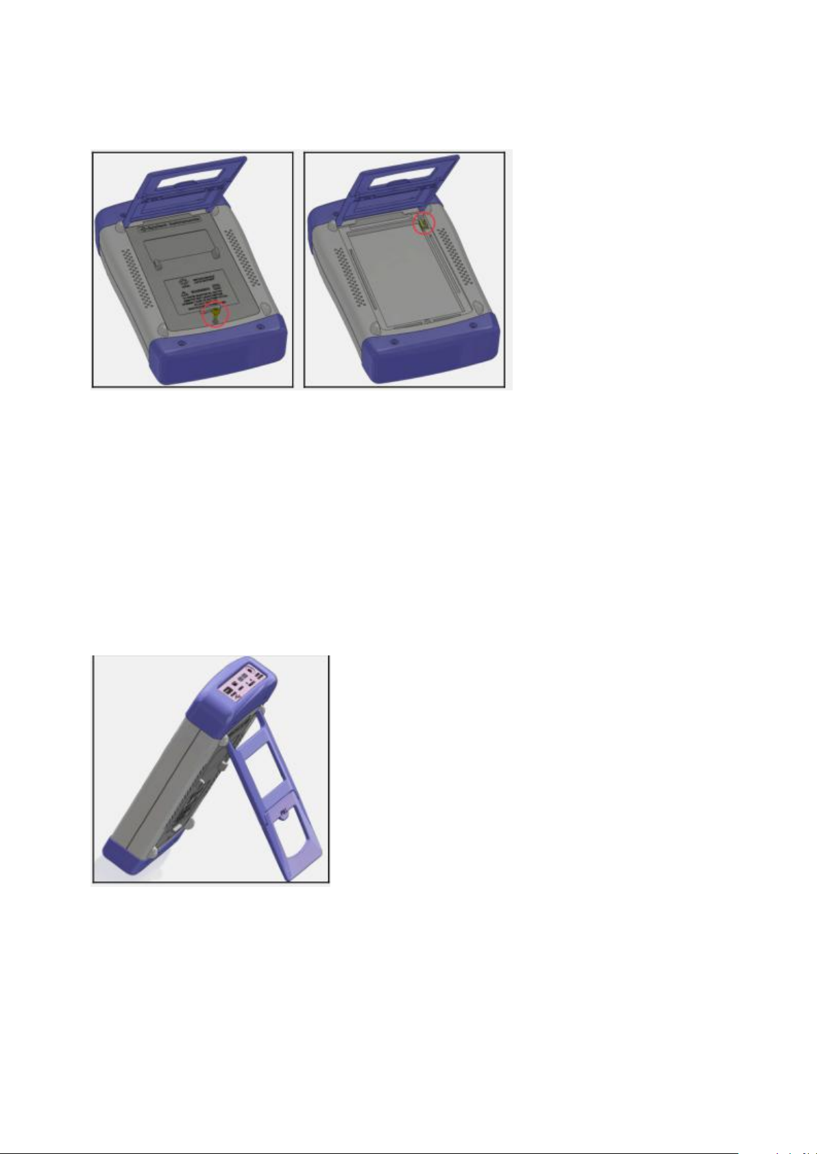
1.5 Replacing the battery .............................................................................................................6
1.6 Adjusting Support ..................................................................................................................7
2. Overview.......................................................................................................................................8
2.1 Introduction ............................................................................................................................8
2.2 Main Specifications ................................................................................................................8
2.3 Main functions ........................................................................................................................8
2.3.1 Calibration function..................................................................................................8
2.3.2 Comparator Function (Sorting Function) ................................................................8
2.3.3 System Settings .......................................................................................................9
2.3.4 Remote Control .......................................................................................................9
3. Start...............................................................................................................................................9
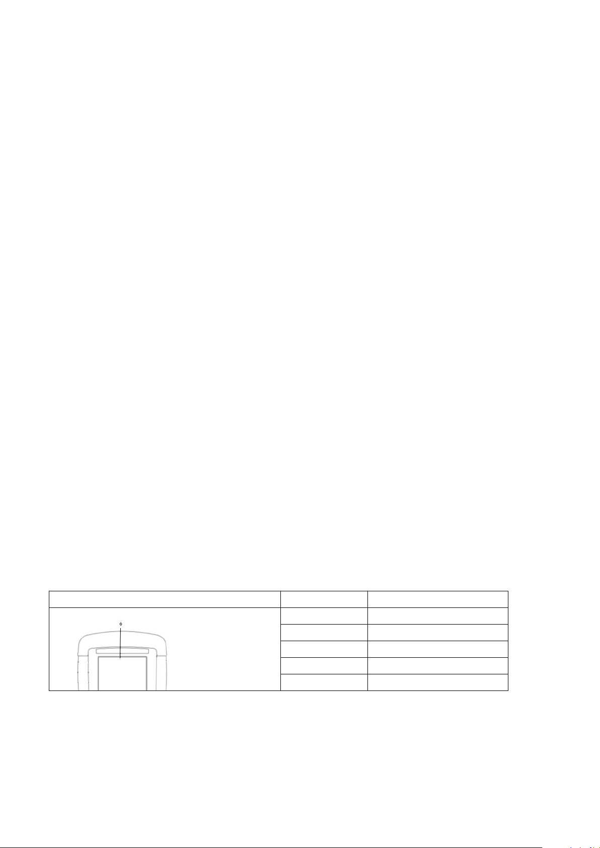
3.1 Front Panel ..................................................................................................................................9
3.2 Interface Panel ...........................................................................................................................10
3.3 Using an external power supply.................................................................................................10
3.3.1 Battery charging function............................................................................................10
3.4 Startup .......................................................................................................................................10
3.5 Connection of test terminal .......................................................................................................10
3.5.1 Test fixture and cable ..................................................................................................11
4. [Meas] Measurement display.......................................................................................................11
4.1 <Measurement Display> page....................................................................................................11
4.1.1 Measurement [Trigger] ...............................................................................................12
4.1.2 Measurement [Range] ................................................................................................12

4/24
4.1.3 Measurement [Beep] ..................................................................................................14
4.1.4 Information bar on <Measurement Display> page ....................................................14
4.1.5 Task bar on the <Measurement Display> page ..........................................................14
4.1.6 Icon of <Measurement Display> page .......................................................................14
4.1.7 [Browse Data] Function Keys.....................................................................................15
4.2 <Browse data> page ..................................................................................................................16
5. [Setup] setting display .....................................................................................................................16
5.1 Measurement settings ................................................................................................................16
5.1.1 Timer ..........................................................................................................................17
5.1.2 Comparator settings ....................................................................................................17
5.1.3 [Nominal Value] Input ................................................................................................17
5.1.4 Setting of [Lower Limit] and [Upper Limit] ..............................................................18
5.2 Clearing the short circuit ...........................................................................................................18
6. System Configuration ......................................................................................................................18
6.1 <System Configuration> page ...................................................................................................18
6.1.1 System [Language] .....................................................................................................19
6.1.2 System [Account], [Password] ...................................................................................19
6.1.3 System [Date], [Time] ................................................................................................20
6.1.4 [Sound] Settings .........................................................................................................20
6.1.5 [Baud rate] setting ......................................................................................................20
6.2 <System Information> page ......................................................................................................22
7. Remote Communication ..................................................................................................................22
7.1 USB-232C .................................................................................................................................22
7.1.1 USB-232C connection ................................................................................................22
7.2 Handshake protocol ...................................................................................................................22
7.3 SCPI Language ..........................................................................................................................23
8. Specifications ..................................................................................................................................23
8.1 Technical indicators ...................................................................................................................23
8.2 General specifications ...............................................................................................................24

5/24
1.Installation and setup wizard
Thank you for purchasing our products! Please read this chapter carefully before use. The
following descriptions are mainly based on JK625.
In this chapter you will learn the following:
● Packing list
● Power requirements
● Operating environment
● cleaning
● Replace the battery
● Adjust support
1.1 packing list
Before using the instrument officially:
1. Check whether the appearance of the product is damaged or scratched;
2. Check the instrument packing list for missing accessories.
If it is damaged or the accessories are insufficient, please contact Jinko Instrument Sales
Department or the distributor immediately.
1.2 Power requirements
The instrument can only use our special AC power adapter and lithium battery.
AC power adapter:
Input voltage: 90V-260VAC, 49Hz ~ 62Hz
Power: up to 10VA
Warning: Do not use power adapters of other specifications. The instrument can only use our
company's power supply and rechargeable lithium battery!
1.3 Operating environment
JK625 must be used under the following environmental conditions:
Temperature: 0 ℃~55 ℃,
Humidity: less than 70% RH at 23 ℃
Altitude: 0 ~ 2000 meters
1.4 Cleaning
Do not clean the inside of the instrument.
Note: Do not use solvents (alcohol or gasoline, etc.) to clean the instrument.
Use a clean cloth and a little water to clean the case and panel.
1.5 Replace the battery
The instrument has a built-in rechargeable lithium battery. The battery is already installed in the
instrument's battery compartment when it leaves the factory. If you replace the battery, follow these
steps
Figure 1-1 Battery replacement

6/24
1. Use a screwdriver to loosen the screws on the battery cover and remove the battery cover.
2. Remove the plug from the old battery and plug in the new battery, paying attention to the
direction of the plug.
3. Insert the new battery into the battery compartment, close the battery cover, and tighten the
screws.
1.6 Adjusting the support
The instrument supports 1 position for user convenience: 60 degrees.
Use the 60-degree position to make the instrument more stable.
Figure 1-2 Support position at 60 degrees

7/24
2. Overview
In this chapter you will learn:
● Introduction
● Main specifications
● Main functions
2.1 Introduction
Thank you for purchasing the JK625 Handheld DC Low Resistance Tester.
JK625 battery internal resistance tester is an instrument that can measure battery internal resistance
and voltage online. It is controlled by a high-performance 32-bit ARM microprocessor. It is a
miniature handheld instrument with automatic real-time detection and a built-in large-capacity
lithium battery to achieve long standby JK625 has the superior performance of both portable and
desktop instruments. The main performance is compatible with Nissho 3554. The instrument can test
0.01mΩ ~ 3.3Ω resistance and 0 ~ 60V DC voltage. The data display is stable. The maximum
resistance is 3300 display digits. Voltage Maximum 6000 display digits.
The resistance measurement of the instrument uses the vector test principle, and the voltage
measurement uses the differential test principle, so the open circuit voltage can be accurately
measured. In addition, the instrument has a professional sorting function, a built-in sorting record,
and GD / NG sorting results show the sorting sound setting, which is applied to the UPS online
battery measurement automatic sorting system to complete a fully automatic assembly line test.
JK625 is equipped with 500 sets of data storage, which can save measurement data with one click,
saving you the time of recording data. And can be equipped with a USB interface for remote control
and data acquisition and analysis, making him very suitable for all kinds of battery assembly line
inspection.
2.2 Main specifications
JK625 hand-held series of technical specifications, including the basic technical indicators of the
instrument and the range allowed by the instrument test. These specifications are achievable at the
factory.
● Basic accuracy: resistance: 0.5%, voltage: 0.05%
● Enter. Frequency: 1kHz
● Maximum display digits: resistance: 3300, voltage 60000
● Range automatic, manual or nominal test-Provides a test range of 0.001mΩ to 3.3Ω.
● Test speed: 1 time / second
● Four-terminal test
● Provide high current and low current test modes-different test modes can be suitable for test
pieces with different properties.
● Display-With 5.6 "inch true color LCD, the measured value and sorting result (GD / NG)
are displayed at the same time.
2.3 Main functions
2.3.1 Calibration function
Full-scale short-circuit clear function.
2.3.2 Comparator function (sorting function)

8/24
Built-in sorting data for GD / NG judgment of the DUT.
●Comparison method:
Absolute tolerance ± TOL sorting: The absolute deviation between the measured value and the
nominal value is compared with the limits of each file.
Percent Tolerance TOL Sorting: The percentage deviation between the measured value and the
nominal value is compared with the limits of each range.
Sequential comparison sorting: the measured value is directly compared with the upper and lower
limits
●Sound setting:
Users can set OFF / GD / NG sound according to their needs.
2.3.3 System Settings
1. Serial switch function
2. Switch between Chinese and English
3. Date and time settings
4. I / O port switch setting
5. U disk switch setting
6. Automatic shutdown time setting
2.3.4 Remote control
Supports a maximum baud rate of 115200bps, compatible with SCPI protocol and ASCII
transmission.
3. Get started
In this chapter you will learn:
● front panel
● Interface panel
● Use external power
● boot
● Test connection
3.1 front panel
Table 3-1 Front panel function description
Front panel
Serial number
Function
1
Task bar function keys
2
cursor keys
3
test terminal
4
Power switch
5
ESC Enter

9/24
6
LCD display window
3.2 Interface Panel
Figure 3-1 Interface panel function description
1. external power supply and charger interface
2. Mini-USB communication interface for remote communication.
3. RS485 expansion interface.
4.USB interface can save data.
3.3 Use of external power
The instrument comes standard with a power adapter.
In addition to supplying power to the instrument, this power supply also charges the lithium battery
inside the instrument, so the power adapter cannot be replaced. It is recommended to use our
company's special power supply.
Figure 3-2 Connecting the external power adapter to the instrument.
Plug the power adapter into the AC adapter input jack on the instrument.
3.3.1 Battery charging function
If the battery is not fully charged, the instrument's charging circuit will automatically start to charge
the internal lithium battery after the power adapter is plugged in. The instrument's built-in indicator
of the power switch key will light up to indicate that charging is in progress. This indicator will
remain lit even after the instrument is turned off, until it goes out when the battery is fully charged.

10/24
3.4 boot
The keys are light touch keys. Press the power key to turn the instrument on or off.
3.5 Test connection
The instrument uses four-terminal tests to improve accuracy.
Before testing, please insert the test lead of the instrument into the instrument jack.
Figure 3-4 Connect the test terminal.
Warning: Do not apply DC voltage or current to the test terminal, otherwise it will damage the
instrument.
Warning: When testing a charged device, make sure that its charge is discharged before measuring.
3.5.1 Test fixtures and cables
According to our company's long-term investigation of users, user-made or other company's test
fixtures or test cables may cause incorrect measurement results. We recommend that you use our test
fixtures or test cables.
The contact springs of our test fixtures are silver-plated or gold-plated, which will cause abrasion of
the electroplated surface during long-term work (such as 1 ~ 2 years). It is recommended that you
replace the new fixtures in time if you find that there are obvious deviations in several tests.
4. [Meas] Measurement display
In this chapter you will learn about all measurement display functions:
● <Measurement Display> page
● Short circuit clear
● <comparator settings> page
4.1 <Measurement Display> page
No matter what page you are on, just press the [Measurement Display] shortcut key to enter the
<Measurement Display> page.
The <Measurement Display> page mainly highlights the measurement results. When comparison is
turned on, sorting results and sorting parameters are displayed.
There are 6 common functions that can be set on this page, including:

11/24
● Trigger – trigger method
● Range-range setting.
● Upper limit of resistance – Upper limit of resistance
● Lower resistance limit – lower resistance limit
● Upper voltage limit – upper voltage limit
● Lower voltage limit – lower voltage limit
Note: The measurement data and sorting results are only valid on the <Measurement Display> page.
Figure 4‐1 <Measurement Display> page
4.1.1 Measurement [Trigger]
The instrument has 2 trigger modes: automatic trigger and manual trigger.
Table 4‐1 Trigger Mode Description
■ Set the trigger mode steps:
Step 1
Select the [Display] function key in the upper column to switch to the
<Measurement Display> page
Step 2
Use the cursor keys to select the [Trigger] field
Step 3
Use the [Enter] function key to select the trigger mode.
Function key
Function
Automatic
trigger mode
Manual
trigger mode
4.1.2 Measurement [Range]
The instrument has 3 measuring ranges: automatic range, manual range and nominal range.
Table 4-2 Test range description
Trigger method
Description
Automatic
is also called continuous test. The trigger signal is continuously
tested by the instrument according to the inherent cycle.
Manual
Each time the [Enter] key is pressed, the instrument performs a
measurement cycle, and the instrument is in a waiting state at other
times.

12/24
Method
Description
Advantages
Disadvantages
Automatic
The instrument automatically
selects the best test range
according to the resistance
value, and the range number
in the range field is set
automatically.
The user does not need
any participation.
The automatic range
needs to predict the
range, and the test
speed will be lower
than the manual range
mode.
Manual
The instrument will always
use the user-specified range
for testing
The test speed is the
fastest
Users need to
participate in range
selection
Nominal
The instrument will
automatically select the best
range for the test based on the
nominal value.
The best way to sort
the test. The fastest
speed.
Only suitable for
sorting test
Table 4-3 Range and corresponding measurement range
Range number
Range definition
Resistance measurement range
3
3Ω
320mΩ~3.3Ω
2
3mΩ
0mΩ~3.3mΩ
1
30mΩ
32mΩ ~330mΩ
0
300mΩ
32mΩ ~330mΩ
There are 3 measuring method
Range method
Description
Advantages
Disadvantages
Automatic
The instrument
automatically
selects the best test
range according to
the impedance
value, and the range
number in the range
field is set
automatically.
The user does
not need any
involvement.
The automatic range
requires the predicted
range, and the test
speed will be lower
than the manual range
mode.
Manual
The instrument will
always use the
user-specified range
for testing.
The test speed
is the fastest.
Users need to
participate in range
selection
Nominal
The instrument will
automatically select
the best range for
testing based on the
nominal value. 。
The best way
to sort tests.
The fastest
Only suitable for
sorting tests.
Note: For detailed specifications of JK625, please refer to the table on the specification page.

13/24
■ Steps for setting test range:
Step 1
Select the [Measurement Display] function key in the upper
bar to switch to the <Measurement Display> page
Step 2
Use the cursor keys to select the [Range] field
Step 3
Use [Enter] to select the range mode
Function key
Function
Automatic AUTO
instrument will automatically select
range
Keep HAND
instrument locked to current range
The nominal
NORMAL
instrument will select the best range
based on the nominal value
Increase INCR +
Increase the range number, while
changing the range to manual range
Decrease DECR-
Decrease the range number while
changing the range to manual range
When the range is automatic, the instrument performs range prediction every measurement
cycle, so the test speed is slightly slower than the locked range. Moreover, during automatic
measurement, frequent range changes will cause slow response. Usually when the instrument is used
for sorting measurement, the automatic range method is not suitable. For sorting users, please select
the nominal range method
4.1.3 Upper and lower limit settings of resistance and voltage
4.1.4 Information bar on <Measurement Display> page
Below the instrument test results, the instrument also displays the sorting results and related
parameters. These information are modified in the <Comparer Settings> main page and are here for
reference.
All pages include a status bar and task bar. When you use the cursor keys to make a selection, the
status bar will prompt related help information, but you cannot operate the status bar. When using
Step 1
Select the [Measurement Display] function key in the upper bar to
switch to the <Measurement Display> page
Step 2
Use the cursor keys to select the [Lower Resistance] or [Lower
Voltage] field;
Step 3
enter data using the numeric keypad
Step 4
Use the cursor keys to select [Resistance Upper Limit] and
[Resistance Lower Limit];
Step 5
enter data using the numeric keypad
Step 6
Repeat 2 ~ 5 to complete the data input of other files.
Enter data using the numeric keypad, then select the unit to complete the operation

14/24
Mini-USB communication, characters can be printed on the status bar.
4.1.6 Task bar of <Measurement Display> page
Below the status bar is the taskbar, which includes:
● Hold-the data remains unchanged and the instrument stops measuring
● System-Switch to the <System Configuration> page
● Key lock – locks the keyboard, but does not affect the measurement on the <Measurement
Display> page
● Time-show time
4.1.7 Icon of <Measurement Display> Page
Table 4-5 Icon Functions
Icon
Function
An internal power source is currently used, namely a lithium
battery.
External power is currently being used. At this time, the side
light on the observation screen: On means charging is on; Off
means charging is complete. Or observe the battery icon: there is
a change in charge indicating that charging is in progress; no
change indicates that charging is complete.
USB flash drive is currently inserted.
H
The current data is held.
T
Temperature compensation is on (not available in AT518L)
20.0℃(example)
Measured temperature (not available in AT518L).
4.2 Short-circuit clear
Press the [Display] shortcut key, and then press the [Short Circuit Clear] function key in the upper
bar to clear the short circuit.
Users can complete the short-circuit zero calibration of the full range or single range under this page
to compensate for external interference factors.
In order to achieve the accuracy specified by the technical indicators, short-circuit clearing is
necessary. Replace the test fixture or test cable. Short-circuit again. When the temperature changes
greatly, please perform short circuit reset in time.
Before starting to zero, please short the test clip as follows.

15/24
Figure 4-2 Correct test terminal short circuit method
The following example is wrong!
Figure 4-3 Incorrect test terminal short circuit method
4.2.1 [Short circuit] Clear
The short-circuit calibration function of the instrument compensates for any remaining resistance (R)
that may exist from the calibration surface determined by the length of the test cable to the
connection point of the device under test.
■ Short-circuit clearing steps:
Step 1
Press the [Display] shortcut key to enter the measurement
<measurement display> main page
Step 2
Press the [Short Circuit Clear] function key in the upper bar again.
Cleared in about 3 seconds, the screen refreshes and flashes
5. [Setup] setting display
In this chapter you will learn about all the setting functions:
● <Measurement Settings> page
5.1 <Measurement Settings> page
At any time, as long as you press the [Measurement Settings] shortcut key, you can enter the
<Measurement Settings> page.
The <Measurement Settings> page can complete all measurement-related settings, but the instrument
does not display measurement results and sorting results, and the instrument is in a waiting state.
These settings include the following parameters:
● Trigger – trigger method
● Range-test range
● Speed-test speed
● Slam – Slam alarm

16/24
● Resistance and voltage comparison method
● Nominal value of resistance and nominal value of voltage
● Upper and lower limit settings
The [Trigger] and [Range] settings can also be set on the <Measurement Display> page. For the
setting of these parameters, please refer to the [Measurement Display] section of the main
measurement page.
Figure 5‐1 <Measurement Settings> page
5.1.1 Speed
According to user needs, the instrument supports 4 measurement speeds.
To set the speed:
Step 1
Select the [Measurement Settings] function key in the upper bar to
switch to the <Measurement Settings> page
Step 2
Use the cursor keys to select the [Speed] field
Step 3
Select the speed you want to set
Function key
Function
Slow test
speed is slow
medium speed
Test speed is medium speed
Fast speed
Test speed is fast
Top speed
Test speed is top speed
5.1.2 Sound
The beep function is effective only when the comparator function is turned on.
The beep setting allows pass, fail, or turn off beeps.
Setting the beeping steps
Step 1
Select the [Measurement Settings] function key in the upper bar to
switch to the <Measurement Settings> page
Step 2
Use the cursor keys to select the [Sound] field
Step 3
Select the desired settings
Function key
Function

17/24
Setting the beeping steps
5.1.3 [Nominal value] input
The absolute and relative values must be entered in a nominal value. Direct reading value
comparison method The nominal value does not participate in the calculation, but in the [standard
[Setup] Setting display
Nominal] In the range mode, the nominal value of the resistance will participate in the range
selection.
Method, you need to enter the correct nominal value of the resistor.
Enter the nominal value:
Step 1
Select the [Measurement Settings] function key in the upper bar to
switch to the <Measurement Settings> page
Step 2
Use the cursor keys to select the [Nominal resistance] or [Nominal
voltage] field;
Step 3
Use the numeric keys to enter data, and the unit to select using the
function keys.
5.1.4 [Lower Limit] and [Upper Limit] settings
Step 1
Select the [Measurement Settings] function key in the upper bar to
switch to the <Measurement Settings> page
Step 2
Use the cursor keys to select the [Lower Resistance] or [Lower
Voltage] field;
Step 3
enter data using the numeric keypad
Step 4
Use the cursor keys to select [Resistance Upper Limit] and
[Resistance Lower Limit]
Step 5
enter data using the numeric keypad
Step 6
Repeat 2 ~ 5 to complete the data input of other files.
Enter data using the numeric keypad, then select the unit to complete the operation.
Note: The instrument shares the same storage space for the three comparison modes, so the
comparator data needs to be reset after switching the comparison mode
6. System settings
Close
Off beep
Pass
The buzzer sounds when the sorting
result is pass (GD)
Failed
The buzzer sounds when the sorting
result is disqualified (NG

18/24
In this chapter you will learn about the system settings of the instrument:
● System Settings Page
● System Information Page
6.1 <System Configuration> page
The <System Configuration> page includes the following settings:
● Serial switch
● Baud rate
● U disk switch
● I / O port
● Display language
● Date
● time
● File name
All the settings on the <System Configuration> page will be automatically saved in the system and
will be loaded automatically at the next boot.
Figure 6‐1 <System Configuration> page;
6.1.1 Serial switch
The instrument supports two states of serial port opening and closing.
■ Set the serial port switch steps:
Step 1
Select the [System Settings] button in the task bar to enter the
<System Settings> page
Step 2
Use the cursor keys to select the [Serial Switch] field.
Step 3
Select Set Serial Switch
Function key
Function
On
Serial port switch on

19/24
Off
Serial port switch off
6.1.2 Baud rate
Set [baud rate]
The instrument has a built-in Mini-USB interface. After sensing the signal conversion of the
Mini-USB interface, the instrument communicates with the host at the set baud rate immediately, and
the keyboard is locked.
In order to communicate correctly, please make sure that the baud rate is set correctly. If the baud
rate between the host computer and the instrument is different, the communication cannot be
performed correctly. Mini-USB is programmed using SCPI language.
The Mini-USB configuration is as follows:
● Data bits: 8 bits
● Stop bit: 1 bit
● Parity: None
● Baud rate: configurable
■ Set the baud rate steps:
Step 1
Select the [System Settings] button in the task bar to enter the
<System Settings> page
Step 2
Use the cursor keys to select the [Baud Rate] field
Step 3
Select the baud rate to be set
Function key
Function
2400
4800
9600
14400
19200
6.1.3 U disk switch
The instrument supports two states of U disk open and close.
■ Steps of setting U disk switch:
Step 1
Select the [System Settings] button in the task bar to enter the
<System Settings> page
Step 2
Use the cursor keys to select the [U disk switch] field
Step 3
Select the setting of U disk switch
Function key
Function
On
U disk switch on
Off
U disk switch off
6.1.4 I / O port
The instrument supports two states of I / O port opening and closing.
■ Setting I / O port switch steps:
This manual suits for next models
1
Table of contents
Other Jinko Test Equipment manuals