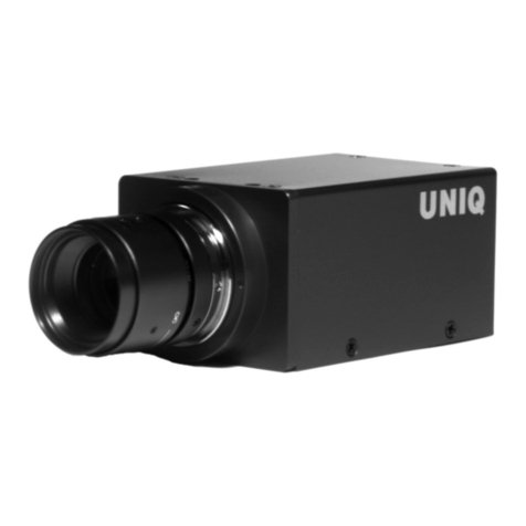
CIS VCC-SXCL3R Quick start guide

VCC-SXCL3R Rev. 905-0046-00
©2016 CIS Corporation. All rights reserved.
Camera Link I/F
SXGA Color Camera
VCC-SXCL3R
Product Specifications
& Operational Manual
CIS Corporation

VCC-SXCL3R Rev. 905-0046-00
©2016 CIS Corporation. All rights reserved.
1
Table of Contents
PAGE
1. Handling Precautions..................................................................................................................................2
2. Product Outline..........................................................................................................................................3
3. System Configuration..................................................................................................................................3
3.1. Camera.................................................................................................................................................3
3.2. Optional Accessories...............................................................................................................................3
3.3. Optional Function...................................................................................................................................3
3.4. Packaging .............................................................................................................................................3
4. Specifications ............................................................................................................................................4
4.1. General Specifications.............................................................................................................................4
4.2. Camera Input and Output Signals Specifications .........................................................................................5
4.3. CMOS Spectral Response.........................................................................................................................6
5. Function Settings .......................................................................................................................................7
5.1. ROI and Frame Rate............................................................................................................................. 11
5.2. Sub-sampling and Frame Rate................................................................................................................11
6. External Connector Pin Assignment.............................................................................................................12
6.1. 6pins Circular Connector HR10-7R-6PA (HIROSE)...................................................................................... 12
6.2. 26pins Small Camera Link Connector 12226-1100-00 PL (SUMITOMO 3M).................................................12
7. Timing Chart................................................................................................................................................ 13
7.1. Horizontal Synchronous Timing ..............................................................................................................13
7.2. Vertical Synchronous Timing ..................................................................................................................14
7.3. Fixed Trigger Shutter Mode.................................................................................................................... 14
7.4. Pulse Width Trigger Shutter Mode...........................................................................................................15
7.5. Note for Trigger Shutter Mode................................................................................................................16
8. Serial Communication Function ..................................................................................................................17
9. Factory Settings....................................................................................................................................... 18
10. CMOS Optical Axis Accuracy.......................................................................................................................19
11. Dimensions .............................................................................................................................................20
12. Cases for Indemnity (Limited Warranty) ......................................................................................................21
13. CMOS Pixel Defect....................................................................................................................................21
14. Product Support.......................................................................................................................................21
15. Ordering Information................................................................................................................................21

VCC-SXCL3R Rev. 905-0046-00
©2016 CIS Corporation. All rights reserved.
2
1. Handling Precautions
The camera must not be used for any nuclear equipments or aerospace equipments with which mechanical failure or
malfunction could result in serious bodily injury or loss of human life. Our warranty does not apply to damages or defects
caused by irregular and/or abnormal use of the product.
Please observe all warnings and cautions stated below.
Our warranty does not apply to damages or malfunctions caused by neglecting these precautions.
Do not use or store the camera in the extremely dusty or humid places.
Do not apply excessive force or static electricity that could damage the camera.
Do not shoot direct images that are extremely bright (e.g., light source, sun, etc.), and when camera is not in use, put the
lens cap on.
Follow the instructions in Chapter 6, “External connector pin assignment” for connecting the camera. Improper
connection may cause damages not only to the camera but also to the connected devices.
Confirm the mutual ground potential carefully before connecting the camera to monitors or computers. Any AC leaks
from the connected devices may cause damages or destroy the camera.
Do not apply excessive voltage. (Use only the specified voltage.) Unstable or improper power supply voltage may cause
damages or malfunction of the camera.
The voltage ripple of camera power DC +12V±10% shall be within ±50mV. Improper power supply voltage may cause
noises on the video signals.
The rising time of camera power supply voltage shall be less than +10V, Max 60ms. Please avoid noises like chattering
when rising.
10 4020 30 50
10
11
12
電 源 電 圧 [V]
電源 電圧 立 ち 上 がり 時間[ ms]
9
8
7
60 70
Voltage Rising Time 【ms】
Power supply
Voltage 【V】

VCC-SXCL3R Rev. 905-0046-00
©2016 CIS Corporation. All rights reserved.
3
2. Product Outline
VCC-SXCL3R is a Camera Link interfaced and 1.3M resolution, small industrial color video camera module. 1.3M pixels,
1/2 type CMOS sensor is utilized.
Features
□29mm cubic in size
□Global shutter CMOS sensor
□Camera Link I/F
□ROI
□Sub-sampling
□External trigger
3. System Configuration
3.1. Camera
・Camera, VCC-SXCL3R
・Lens cap
3.2. Optional Accessories
・None
3.3. Optional Function
・None
3.4. Packaging
・Individual carton
・Master carton (10pcs/carton)
Note) Master carton may vary depends on the quantity to be shipped.

VCC-SXCL3R Rev. 905-0046-00
©2016 CIS Corporation. All rights reserved.
4
4. Specifications
4.1. General Specifications
(1) Pickup device
Device Type
1/2 type Global Shutter CMOS Image Sensor
Effective pixel number
1280(H) ×1024(V)
Unit cell size
4.8μm(H) ×4.8μm(V)
(2) Video output frequency
Pixel Clock
72.000 MHz
Frame rate
1Tap CL Clock 72MHz
41.9Hz
2Tap CL Clock 36MHz
41.9Hz
2Tap CL Clock 72MHz
83.8Hz
※2Tap 8Bit output (Factory setting)
3Tap CL Clock 72MHz
151.7Hz
(3) Sync system
Internal Sync. System.
(4) Video output
Camera Link /PoCL RAW DATA output
(5) Resolution
1024TV lines
(6) Output format
8bit / 10bit
(7) Sensitivity
F5.6 2000 lx (Shutter speed 1/85s, Gain 0dB)
※2Tap 8Bit output (Factory setting)
(8) Minimum illumination
F1.4 35lx (Shutter speed 1/85s, Gain+12dB)
※2Tap 8Bit output (Factory setting)
(9) Dust or stains in optical system
No dust or stain shall be detected on the testing screen with setting the camera aperture at F11.
(10) Power requirements
DC+12V±10%
※PoCL supported
(11) Power consumption
Typ. 2.0W (at DC+12V IN) 2Tap 8Bit 72MHzROI:OFF Gain:x1 Shutter:OFF
(12) Dimensions
Refer to overall dimension drawing. (H:29mm W:29mm D:29mm excluding projection)
(13) Weight
Approx. 50g
(14) Lens mount
C Mount ※Refer to overall dimension drawing.
(15) Optical axis accuracy
Refer to drawing for CMOS Optical Axis Accuracy.
(16) Gain variable range
x1~x32
※image quality guaranteed range x1~x4
(17) Shutter speed variable range
OFF(1/84),1/250,1/500,1/1000,1/2000,1/4000,1/10000s
※2Tap 8Bit output (Factory setting)
(18) Trigger shutter mode
・Fixed Shutter Trigger Mode/
・Pulse Width Shutter Trigger Mode (Exposure time is set by the pulse width of the trigger signals.)
(19) Safety/Quality standards
UL: Conform to UL Standard including materials and others.
CE:
EN55022:2010 (ClassA) for Emission
EN61000-6-2:2005 for Immunity
RoHS:
Conform to RoHS.
(20) Durability
Vibration
Acceleration
: 98m/s2 (10G)
Frequency
: 20~200 Hz
Direction
: X,Y, and Z 3 directions
Testing time
: 120min for each direction
Shock
No malfunction shall be occurred with 980m/s2(100G) for ±X,±Y, and ±Z,
6 directions. (without package)
(21) Operational environment
Temperature:
Performance guaranteed temperature: 0℃~+40℃
Camera operation guaranteed temperature: -5℃~+45℃
Humidity:
RH 20~80% with no condensation.
※All the specifications specified in this manual is guaranteed under performance guaranteed
temperature.
※All the camera functions operate normally under operation guaranteed temperature.
(22) Storage environment
Temperature:
-25℃~+60℃
Humidity:
RH 20~80% with no condensation.

VCC-SXCL3R Rev. 905-0046-00
©2016 CIS Corporation. All rights reserved.
5
4.2. Camera Input and Output Signals Specifications
(1) Video output
data
Effective Video Output
1280(H) x 1024(V)
At full frame scan mode
RAW DATA Output details
(2) Sync. Signal
input and output
FVAL output
LVDS
Camera Link connector
LVAL output
LVDS
DVAL output
LVDS
EEN output
Open corrector
6pins Circular connector
Trigger Input
Photo Coupler
(3) Trigger Input
The minimum width of the
trigger pulse
Within 110μS ~20mS
Camera Link Input
LVDS : CC1 input
Camera Link connector
TTL input
6pins Circular connector
【Reference】
Trigger IN terminal of 6pins circular connector for external control is electronically insulated. Trigger IN terminal
(TRIG_IN in the drawing below) shall be capable of 10mA~20mA. EEN OUT terminal (EEN_OUT in the drawing
below) needs power, 3.3V~20V,
and due to its load resistance, 0.5mA~5mA needs to be added.
※3 seconds shall be waited after turning on power to get proper camera operation.
Horizontal
Vertical

VCC-SXCL3R Rev. 905-0046-00
©2016 CIS Corporation. All rights reserved.
6
4.3. CMOS Spectral Response
Please refer to the values for Red, Green, and Blue.
※The lens characteristics and illuminant characteristics are excluded.

VCC-SXCL3R Rev. 905-0046-00
©2016 CIS Corporation. All rights reserved.
7
5. Function Settings
(Camera functions can be set with serial communications.)
Function
Address
Data
Output bit length and
tap width
2
0:
1Tap 8bit Output
CLK:72MHz
1280(H)×1024(V)
1:
1Tap 10bit Output
CLK:72MHz
1280(H)×1024(V)
2:
2Tap 8bit Output
CLK:36MHz
640×2Tap(H)×1024(V)
3:
2Tap 10bit output
CLK:36MHz
640×2Tap(H)×1024(V)
4:
2Tap 8bit Output
CLK:72MHz
640×2Tap(H)×1024(V)
5:
2Tap 10bit output
CLK:72MHz
640×2Tap(H)×1024(V)
6:
3Tap 8bit Output
CLK:72MHz
424×3Tap(H)×1024(V)
Trigger shutter mode
3
0:
Normal shutter mode (Trigger shutter mode OFF)
1:
Fixed trigger shutter mode (Shutter speed can be set with address 23.)
2:
Pulse width trigger shutter mode
(Shutter speed can be set with trigger pulse width.)
Trigger input settings
4
0:
Camera Link CC1
Positive polarity input
1:
Camera Link CC1
Negative polarity input
2:
6pin Connector Trig +
Positive polarity input
3:
6pin Connector Trig +
Negative polarity input
4:
6pin Connector Trig -
Positive polarity input
5:
6pin Connector Trig -
Negative polarity input
Black level control values
7
0~15:
Output black level (8bit) = (Set value)
Factory setting
Output black level (10bit) = (Set value) ×4
Defective pixel correction
13
0:
Defective pixel correction OFF
1:
Defective pixel correction ON
Gain control mode
20
0:
0dB
X1
Factory setting
1:
3.5dB
X1.5
2:
6dB
X2
3:
9.5dB
X3
4:
12dB
X4
5:
15.5dB
X6
6:
18dB
X8
15:
Manual gain control (Gain can be set with address 21.)
Manual gain control
21
0~124:
0~30dB
Shutter time settings
23
At normal shutter mode
At trigger shutter mode ※1
1Tap &
2Tap 36MHz
2Tap
3Tap
1Tap &
2Tap 36MHz
2Tap
3Tap
0:
1/45s
1/85s
1/155s
1/45s
1/85s
1/155s
1:
1/258s
1/254s
1/252s
1/250s
1/250s
1/250s
2:
1/533s
1/517s
1/509s
1/503s
1/501s
1/501s
3:
1/1165s
1/1067s
1/1039s
1/1014s
1/1007s
1/1004s
4:
1/2688s
1/2331s
1/2169s
1/2057s
1/2028s
1/2016s
5:
1/4237s
1/5376s
1/4761s
1/4237s
1/4115s
1/4065s
6:
1/11560s
1/10752s
1/10416s
1/11627s
1/10752s
1/10416s
15:
Manual shutter control (Manual shutter can be set with the address 24.)
※1At trigger shutter mode (No overlapped).

VCC-SXCL3R Rev. 905-0046-00
©2016 CIS Corporation. All rights reserved.
8
Function
Address
Data
Manual shutter control
24
At trigger shutter mode (Non overlapped).
1Tap &
2Tap 36MHz
11~1990
Set value (16bit) x 10us -14μs
96μs ~
19886μs
2Tap
11~1176
Set value (16bit) x 10us - 7μs
103μs ~
11753μs
3Tap
11~645
Set value (16bit) x 10us - 4μs
106μs ~
6446μs
White balance control
30
0:
Through
1:
Spared for preset use
2:
Manual white balance
(Set with the address 31, 32, and 33.)
Manual White balance
control (R)
31
0~800
0~800%
Manual White balance
control (B)
33
0~800
0~800%
One push white balance
34
0:
No function
1:
Start operation
Return to 0 after completion of operation.
ROI
50
0:
1280(H)×1024(V)
At 3Tap ⇒
1272(H)×1024(V)
1:
1280(H)×960(V)
At 3Tap ⇒
1272(H)×960(V)
2:
1024(H)×1024(V)
At 3Tap ⇒
1020(H)×1024(V)
3:
1024(H)×768(V)
At 3Tap ⇒
1020(H)×768(V)
4:
800(H)×600(V)
At 3Tap ⇒
792(H)×600(V)
5:
640(H)×480(V)
At 3Tap ⇒
636(H)×480(V)
Sub-sampling mode
56
0:
Sub-sampling OFF
1280(H) x 1024(V)
At 3Tap ⇒
1272(H)×1280(V)
1:
Sub-sampling ON
640(H) x 512(V)
At 3Tap ⇒
636(H)×512(V)
※Note). At normal shutter mode, the followings shall be carefully considered with manual shutter control.
1Tap & 2Tap 36MHz
ROI Setting
Manual shutter setting value
Formula for Exposure Time
1280(H)×1024(V)
11~43
Setting value (16bit) x 10us -13.6μs
1280(H)×960(V)
11~65
1024(H)×1024(V)
11~42
1024(H)×768(V)
11~51
800(H)×600(V)
11~37
640(H)×480(V)
11~34
Sub-sampling mode
11~26

VCC-SXCL3R Rev. 905-0046-00
©2016 CIS Corporation. All rights reserved.
9
ROI Setting
Manual shutter setting value
Formula for Exposure Time
1280(H)×1024(V)
44
45
420.6μs
420.6μs
1280(H)×960(V)
66
67
641.7μs
641.7μs
1024(H)×1024(V)
43
44
410.6μs
410.6μs
1024(H)×768(V)
52
53
503.4μs
503.4μs
800(H)×600(V)
38
39
362.8μs
362.8μs
640(H)×480(V)
35
328.4μs
Sub-sampling mode
27
246.7μs
ROI Setting
Manual shutter setting value
Formula for Exposure Time
1280(H)×1024(V)
46~1990
設定値 x 10us –124.1μs
1280(H)×960(V)
68~1990
設定値 x 10us –124.1μs
1024(H)×1024(V)
45~1990
設定値 x 10us –124.3μs
1024(H)×768(V)
54~1525
設定値 x 10us –124.3μs
800(H)×600(V)
40~1000
設定値 x 10us –124.1μs
640(H)×480(V)
36~710
設定値 x 10us –124.1μs
Sub-sampling mode
28~735
設定値 x 10us –79.7μs
(There is a jitter for 1H with the calculated value)
2Tap
ROI Setting
Manual shutter setting value
Formula for Exposure Time
1280(H)×1024(V)
11~21
Setting value (16bit) x 10us –6.8μs
1280(H)×960(V)
11~32
1024(H)×1024(V)
11~21
1024(H)×768(V)
11~21
800(H)×600(V)
11~18
640(H)×480(V)
11~17
Sub-sampling mode
11~13
ROI Setting
Manual shutter setting value
Formula for Exposure Time
1280(H)×1024(V)
22
210.3μs
1280(H)×960(V)
33
320.9μs
1024(H)×1024(V)
22
205.3μs
1024(H)×768(V)
22
205.3μs
800(H)×600(V)
19
181.4μs
640(H)×480(V)
18
115.5μs
Sub-sampling mode
14
96.9μs

VCC-SXCL3R Rev. 905-0046-00
©2016 CIS Corporation. All rights reserved.
10
ROI Setting
Manual shutter setting value
Formula for Exposure Time
1280(H)×1024(V)
23~1176
設定値 x 10us –62.0μs
1280(H)×960(V)
34~1124
設定値 x 10us –62.0μs
1024(H)×1024(V)
23~989
設定値 x 10us –62.1μs
1024(H)×768(V)
23~750
設定値 x 10us –62.1μs
800(H)×600(V)
20~500
設定値 x 10us –62.0μs
640(H)×480(V)
19~345
設定値 x 10us –62.0μs
Sub-sampling mode
15~370
設定値 x 10us –39.8μs
(There is a jitter for 1H with the calculated value)
3Tap
ROI Setting
Manual shutter setting value
Formula for Exposure Time
1272(H)×1024(V)
11~12
Setting value (16bit) x 10us –3.4μs
1272(H)×960(V)
11~21
1020(H)×1024(V)
11~12
1020(H)×768(V)
11~15
792(H)×600(V)
Refer to the chart below
636(H)×480(V)
Refer to the chart below
Sub-sampling mode
Refer to the chart below
ROI Setting
Manual shutter setting value
Formula for Exposure Time
1272(H)×1024(V)
13
120.9μs
1272(H)×960(V)
22
186.3μs
1020(H)×1024(V)
13
97.1μs
1020(H)×768(V)
16
125.0μs
792(H)×600(V)
Refer to the chart below
636(H)×480(V)
Refer to the chart below
Sub-sampling mode
Refer to the chart below
ROI Setting
Manual shutter setting value
Formula for Exposure Time
1272(H)×1024(V)
14~645
Setting value x 10us –33.9μs
1272(H)×960(V)
23~615
Setting value x 10us –33.4μs
1020(H)×1024(V)
14~531
Setting value x 10us –32.4μs
1020(H)×768(V)
17~406
Setting value x 10us –32.4μs
792(H)×600(V)
11~254
Setting value x 10us –30.8μs
636(H)×480(V)
11~181
Setting value x 10us –30.9μs
Sub-sampling mode
11~183
Setting value x 10us –19.8μs
(There is a jitter for 1H with the calculated value)

VCC-SXCL3R Rev. 905-0046-00
©2016 CIS Corporation. All rights reserved.
11
5.1. ROI and Frame Rate
Setting modes
Output conditions and corresponding frame rates
1Tap
2Tap
3Tap
ROI 0
(ROI OFF)
Pixel number
1280x1024
1280x1024
1272x1024
Frame rate
41.9fps
83.8 fps
151.7 fps
Total CLK number
for 1 Line
1592CLK
796 CLK
440 CLK
ROI 1
Pixel number
1280x960
1280x960
1272x960
Frame rate
44.1 fps
88.2 fps
160.3 fps
Total CLK number
for 1 Line
1592 CLK
795 CLK
432 CLK
ROI 2
Pixel number
1024x1024
1024x1024
1020x1024
Frame rate
49.5 fps
99.0 fps
186.1 fps
Total CLK number
for 1 Line
1336 CLK
668 CLK
351 CLK
ROI 3
Pixel number
1024x768
1024x768
1020x768
Frame rate
64.3 fps
129.4 fps
242.6 fps
Total CLK number
for 1 Line
1355 CLK
668 CLK
351 CLK
ROI 4
Pixel number
800x600
800x600
792x600
Frame rate
95.9 fps
191.8 fps
383.7 fps
Total CLK number
for 1 Line
1112 CLK
556 CLK
276 CLK
ROI 5
Pixel number
640x480
640x480
636x480
Frame rate
133.9 fps
267.7 fps
535.4 fps
Total CLK number
for 1 Line
952 CLK
476 CLK
237 CLK
5.2. Sub-sampling and Frame Rate
Setting modes
Output conditions and corresponding frame rates
1Tap
2Tap
3Tap
Sub-sampling OFF
Pixel number
1280x1024
1280x1024
1272x1024
Frame rate
41.9fps
83.8 fps
151.7 fps
Total CLK number
for 1 Line
1592 CLK
796 CLK
440 CLK
Sub-sampling ON
Pixel number
640x512
640x 512
636x512
Frame rate
132.2 fps
264.4 fps
528.9 fps
Total CLK number
for 1 Line
952 CLK
476 CLK
237 CLK

VCC-SXCL3R Rev. 905-0046-00
©2016 CIS Corporation. All rights reserved.
12
6. External Connector Pin Assignment
6.1. 6pins Circular Connector HR10-7R-6PA (HIROSE)
6.2. 26pins Small Camera Link Connector 12226-1100-00 PL (SUMITOMO 3M)
※Never supply power via both 6pins circular connector and 26pins small Camera Link connector at the same time.
It may cause malfunction of the camera.
HR10-7R-6PA
(HIROSE)
Pin No.
Signal Name
Description
1
Power IN
non-PoCL: Power Input (DC 12V typical)
2
NC
Not used
3
EEN OUT
Exposure Enable Output (Open Collector)
4
Trigger IN-
Trigger Input- (Isolated)
5
Trigger IN+
Trigger Input+ (Isolated)
6
GND
GND (for Pin 1)
Camera Link Base Configuration
PoCL/non-PoCL
12226-1100-00PL (3M)
Pin No.
Signal Name
Description
1,26
Power IN or
GND
PoCL : DC 12VPower Input
non-PoCL: GND
13,14
GND
GND
2,15
X0-, X0+
X0_OUT0
differential pair for transmission
3,16
X1-, X1+
X1_OUT1
differential pair for transmission
4,17
X2-, X2+
X2_OUT2
differential pair for transmission
5,18
Xclk-, Xclk+
CLK OUT
differential pair for transmission
6,19
X3-, X3+
X3_OUT3
differential pair for transmission
7,20
SerTC+, SerTC-
RXD Input
differential pair for reception
8,21
SerTFC-, SerTFC+
TXD Output
differential pair for transmission
9,22
CC1-, CC1+
Trigger Input
differential pair for reception
10,23
CC2+, CC2-
Reserve
differential pair for reception
11,24
CC3-, CC3+
Not used
12,25
CC4+, CC4-
Not used
1
2
3 4
5
6

VCC-SXCL3R Rev. 905-0046-00
©2016 CIS Corporation. All rights reserved.
13
LVAL Out
~
~
Effective Data :640 CLK 156 CLK
DVAL Out
1H = 796 CLK
~
~
Camera Link Port B ・ ・ ・ ・ ・ ・ ・ ・ ・ ・ ・ ・
Camera Link Port A 1 3 ・ ・ ・ ・ ・ ・ ・ ・ ・ ・ ・ ・
5 7
2 4 6 8
1273 1275 1277 1279
1274 1276 1278 1280
12
Video Out 1
2
7
9
1
2
8
0
~
~
LVAL Out
~
~
Effective Data :424 CLK 16 CLK
DVAL Out
1H = 440 CLK
~
~
Camera Link Port B ・ ・ ・ ・ ・ ・ ・ ・ ・ ・ ・ ・
Camera Link Port A 1 4 ・ ・ ・ ・ ・ ・ ・ ・ ・ ・ ・ ・
710
2 5 8 11 414 417 420 423
415 418 421 424
12
Video Out 4
2
3
4
2
4
~
~
Camera Link Port C
3
1
2
8
0
36 9 12
422419416413
7. Timing Chart
7.1. Horizontal Synchronous Timing
1Tap output
2Tap output
3Tap output

VCC-SXCL3R Rev. 905-0046-00
©2016 CIS Corporation. All rights reserved.
14
Effective Line : 1024H
Effective Line
~
~
Exposure Out
1
0
2
4
1
TRIG IN
FVAL
Video Out
LVAL
~
~
1
0
2
4
1
Effective Line
Exposure Time
Delay
(A)
TRIG IN
Exposure Out
Exposure Time
Trigger input ignore period
Image
Header
IDLE StreamPacket Image
Header StreamPacketIDLE IDLE
7.2. Vertical Synchronous Timing
FVAL Out
1Frame = 1078H
Effective Line : 1024H
DVAL Out
~
~
LVAL Out
~
~
Effective Line
~
~~
~
1024 10241 1
Video Out
Effective Line
ineffect
ive line
Effective Line
ineffect
ive line
V Blanking
5 or 54H
※Ineffective lines occur when exposure start is overlapped at trigger mode as well.
7.3. Fixed Trigger Shutter Mode
1Tap:13.72μS delay +48nS jitter
2Tap:6.89μS delay +24nS jitter
3Tap:3.51μS delay +12nS jitter

VCC-SXCL3R Rev. 905-0046-00
©2016 CIS Corporation. All rights reserved.
15
Effective Line : 1024H
Effective Line
~
~
1
0
2
4
1
~
~
1
0
2
4
1
Effective Line
Trigger input ignore period
Exposure Time
Delay
Exposure Time
Delay
(A)
TRIG IN
Exposure Out
① ②
Exposure Time
Image
Header
IDLE StreamPacket Image
Header StreamPacket IDLEIDLE
7.4. Pulse Width Trigger Shutter Mode
The minimum pulse width: 110μs
①②
1Tap:13.72μS delay + 48nS jitter 1Tap:198nS delay +48nS jitter
2Tap:6.89μS delay + 24nS jitter 2Tap:138nS delay +24nS jitter
3Tap:3.51μS delay + 12nS jitter 3Tap:116nS delay +12nS jitter

VCC-SXCL3R Rev. 905-0046-00
©2016 CIS Corporation. All rights reserved.
16
7.5. Note for Trigger Shutter Mode
①When the camera is initialized with trigger mode, dummy trigger signals shall be input 3times and more to
make the operation of CMOS stable.
②At trigger shutter mode, if the next trigger is input with a timing to complete exposure within 3H after FVAL
became “L”, the camera may stop outputting its images. When the camera stops operating, or when proper
image data cannot be output, send “SRST”command to re-start the camera.
※There might be a case when video out becomes black (black out).
TRIGGER
Exposure
FVAL
TRIGGER
Exposure
FVAL
③At trigger shutter mode, please be carefully noted the reduction of exposure time when the next trigger is
overlapped.
Please refer to the Section 5. Function Settings, Note for Manual shutter control at normal shutter mode.
④Do not input the next trigger during the exposure time with the timing as shown as (A) of Section 7.3.
Do not complete exposure of the next trigger while Reading out with the timing as shown as (A) of Section 7.4.
The next exposure can be started while reading out.
⑤Do not change the output Tap at trigger shutter mode. To change output Tap, change the mode to normal
shutter mode first.
⑥Ineffective lines would occur when exposure starts while outputting video at trigger mode. (Please refer to
Section 7.2. Vertical Sync Timing.

VCC-SXCL3R Rev. 905-0046-00
©2016 CIS Corporation. All rights reserved.
17
8. Serial Communication Function
The camera can be controlled externally via Camera Link serial communication function.
(1) The settings for RS232C
Baud rate
:115200bps or 9600bps
Data
:8bit
Stop bit
:1bit
Parity
:None
XON/XOFF
:None
(2) Control code
・The control code is ASCII code.
・The control code consists of command, parameter and CR (0x0d) or LF (0x0a). The Camera setting
data (including changes made) can be obtained by executing the command from PC to the Camera.
(3) How to set a Command
{Command Name} {Parameter 1} {Parameter 2} {Parameter 3}…
・Input {Parameter n}
With hexadecimal notation.
Start inputting with “0x” or “0X”.
Case-insensitive (Either a~f or A~F can be input).
Input range: 0x0000~0xFFFF
With decimal notation.
Only “0”~“9”can be input.
Input range: 0~65535
・At initialization, Prompt “>”is indicated after command is processed.
・Input command in capital letters following to the Prompt.
・Letters can be input up to 80 characters.
・Separate between a command and a parameter by one space.
・From the head of input character to the linefeed code CR (0x0d) or LF (0x0a) is analyzed as one command.
・Refer to the Section 5., Function Settings, for the detailed settings of address and data.
・The command from the PC will be received by the camera, and then echoed back.
Command
Parameter 1
Parameter 2~7
Function
GU
Address
not used
Obtain a setting data
SU
Address
Data
Change a camera setting
SRST
not used
not used
REST the sensor
(Refer to Section 7.5. ②)
INIT
not used
not used
Return to the initial setting
SAVE
not used
not used
Save the settings to EEP-ROM
GSI
not used
Data
Camera information received
Data 1: Model name

VCC-SXCL3R Rev. 905-0046-00
©2016 CIS Corporation. All rights reserved.
18
【Example for Get Command】
To get the information of the address 10
[Send] GU[sp]10[¥r] or[¥n]
[Returned value] 50[¥r] [¥n] [Acquired data + Linefeed]
[Returned value] [¥r] [¥n] [Linefeed]
[Returned value] >[sp] [Prompt + Space]
【Example for Set Command】
To set 30 to the address 10
[Send] SU[sp]10[sp]30[¥r]or[¥n]
[Returned value] [¥r] [¥n] [Linefeed]
[Returned value] >[sp] [Prompt + Space]
【Example for SAVE Command】
[Send] SAVE[¥r]or[¥n]
[Returned value] [¥r] [¥n] [Linefeed]
[Returned value] >[sp] [Prompt + Space]
[¥r]=CR(0x0D)
[¥n]=LF(0x0A)
[sp]=Space(0x20)
9. Factory Settings
Function
Address
Data
Output bit length and
Tap width
2
4:
2Tap 8bit Output ※CLK:72MHz 640×2Tap (H) x 1024 (V)
Trigger shutter mode
3
0:
Normal shutter mode (Trigger shutter mode OFF)
Trigger input settings
4
0:
Camera Link CC1 ※Positive polarity input
Black level control value
7
0:
Output black level (8bit) = (setting value)
Defective pixel correction
13
1:
Defective pixel correction ON
Gain control mode
20
0:
X1
Manual gain control
21
0:
X1
Shutter time settings
23
At normal shutter mode
At trigger shutter mode
1Tap &
2Tap 36MHz
2Tap
3Tap
1Tap &
2Tap 36MHz
2Tap
3Tap
0:
1/45s
1/85s
1/155s
1/45s
1/85s
1/155s
Manual shutter control
24
11
:
1Tap &2Tap 36MHz
96μs
2Tap
103μs
3Tap
106μs
White balance control
30
0:
Through
One push white balance
34
0:
No function available
ROI
50
0:
1280 (H) x1024 (V)
At 3Tap ⇒1272 (H) x 1024 (V)
Sub-sampling mode
56
0:
1280 (H) x 1024 (V)
At 3Tap ⇒1272 (H) x 1280 (V)

VCC-SXCL3R Rev. 905-0046-00
©2016 CIS Corporation. All rights reserved.
19
10. CMOS Optical Axis Accuracy
Table of contents
Other CIS CCTV Camera manuals

CIS
CIS Vision:mini VCC-F22U29APCL Quick start guide

CIS
CIS DCC-4KZM Quick start guide

CIS
CIS VCC-HD1000A Quick start guide

CIS
CIS VISION:mini VCC-F22S29APCL Quick start guide

CIS
CIS VCC-HD5 Quick start guide

CIS
CIS VCC-F32U29CL Installation instructions

CIS
CIS VISION:mini VCC-F22S29ACL Quick start guide

CIS
CIS VCC-FC21U19OP Quick start guide

CIS
CIS VCC-HD3N Quick start guide

CIS
CIS NDI DCC-4KNDI Installation instructions