CIS DCC-4KZM Quick start guide

Rev. 905-0202-00
©2019, ©2020, ©2021 CIS Corporation. All rights reserved.
3G-SDI × 4ch
4K UHDTV CMOS
AF ZOOM Color Camera Module
DCC-4KZM
Product Specification
& Operational Manual
CIS Corporation

DCC-4KZM Rev. 905-0202-00
©2019, ©2020, ©2021 CIS Corporation. All rights reserved.
Table of Contents
1. Handling Precautions.............................................................................................................................................. 1
1.1. Camera Handling Precautions....................................................................................................................... 1
1.2. Restrictions on Applications.......................................................................................................................... 1
1.3. Disclaimers (Exception Clause) ..................................................................................................................... 1
2. Product Outline ...................................................................................................................................................... 2
2.1. Features...................................................................................................................................................... 2
2.2. Accessories ................................................................................................................................................. 2
3. Specifications......................................................................................................................................................... 3
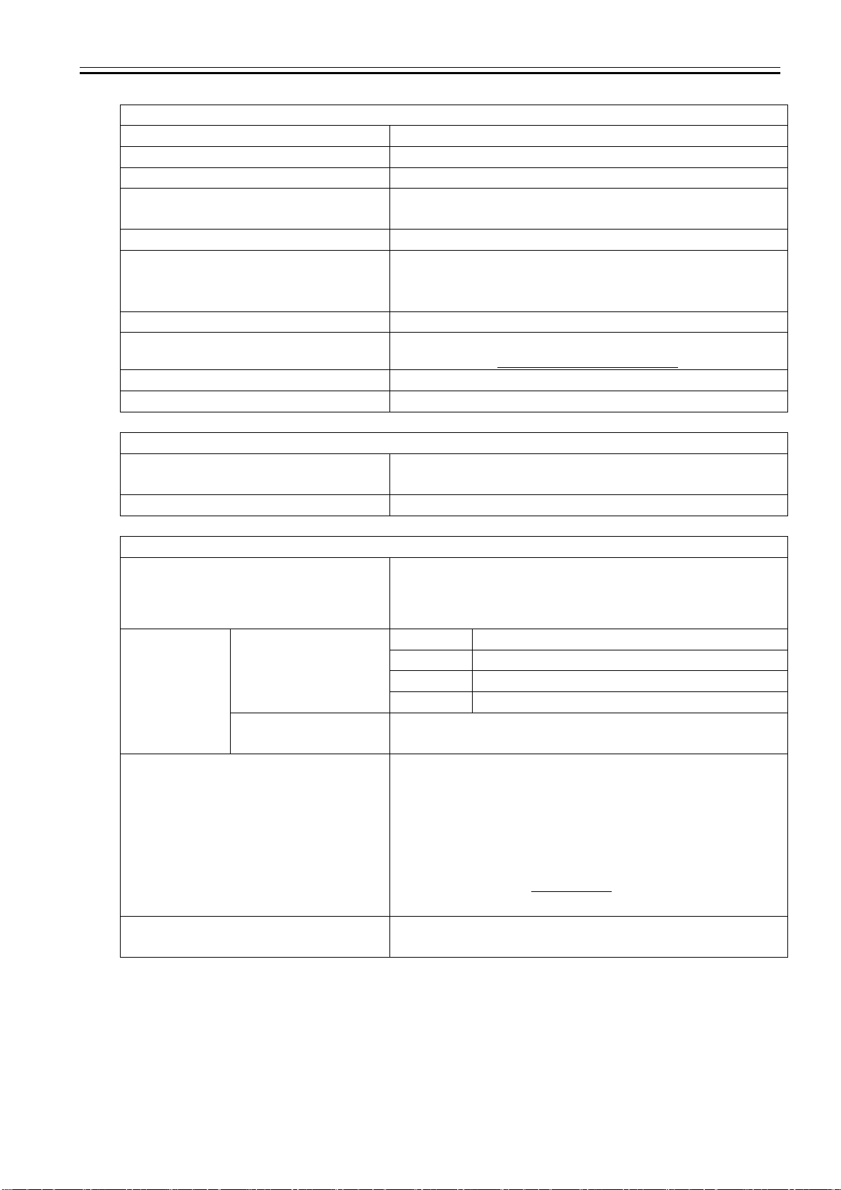
3.1. General Specifications.................................................................................................................................. 3
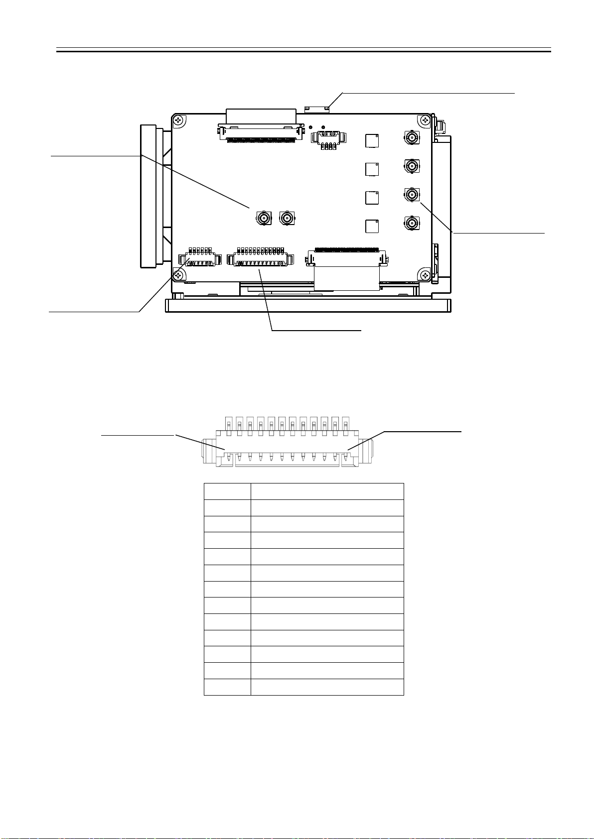
3.2. External Connectors..................................................................................................................................... 5
3.2.1 Control Connector 1................................................................................................................................ 5
3.2.2 Control Connector 2................................................................................................................................ 6
3.2.3 Control Connector 3................................................................................................................................ 6
3.2.4 Video Output Connector.......................................................................................................................... 6
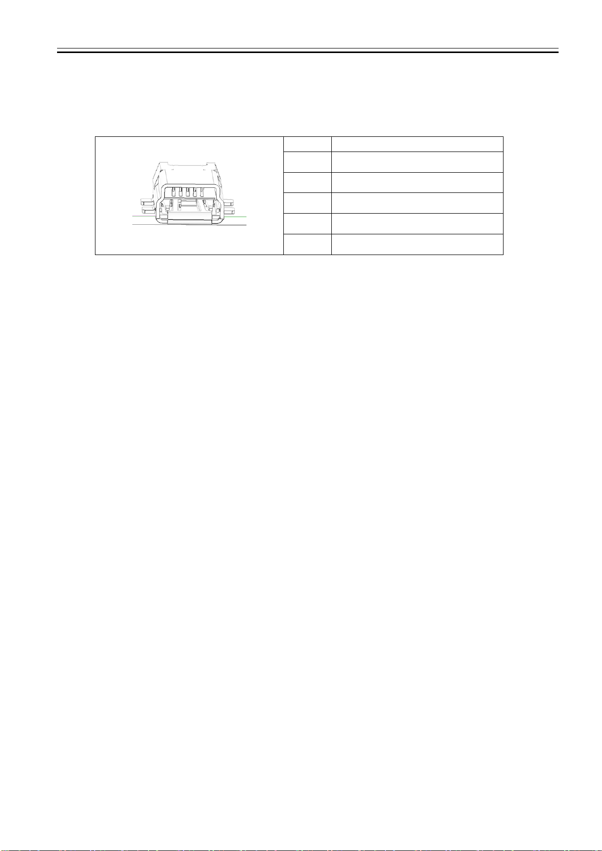
3.2.5 mini USB Connector................................................................................................................................ 7
4. Camera Functions .................................................................................................................................................. 8
4.1. GenLock...................................................................................................................................................... 8
4.2. LTC (Longitudinal Time Code) ...................................................................................................................... 8
4.3. Defective Pixel Correction............................................................................................................................. 9
4.3.1 Defective Pixel Data Type........................................................................................................................ 9
4.3.2 Details on Defective Pixel Data ................................................................................................................ 9
4.3.3 Notes for Defective Pixel Correction....................................................................................................... 10
5. Serial Communication........................................................................................................................................... 11
5.1. Serial Communication Settings ................................................................................................................... 11
5.1.1 Changing Speed of Serial Communication .............................................................................................. 12
5.2. Command List ........................................................................................................................................... 13
5.3. Quick Reference Table for Gain Settings ...................................................................................................... 25
5.4. Quick Reference Table for Shutter Settings.................................................................................................. 26
5.5. Quick Reference Table for Iris Settings........................................................................................................ 27
6. Dimensions.......................................................................................................................................................... 28
6.1. Camera Dimensions ................................................................................................................................... 28
7. Case for Indemnity (Limited Warranty) .................................................................................................................. 29
7.1. Product Warranty....................................................................................................................................... 29
7.2. CMOS Defective Pixels ............................................................................................................................... 29
8. Product Support................................................................................................................................................... 29

DCC-4KZM Rev. 905-0202-00
©2019, ©2020, ©2021 CIS Corporation. All rights reserved.
1
1. Handling Precautions
1.1. Camera Handling Precautions
□Please make sure to take appropriate measures for heat dissipation. Operating camera module without taking
appropriate heat dissipation may cause damages or malfunction.
□Do not use or store camera module in dusty or humid places.
□Please make sure to use fully dust-proof chassis/casing to avoid dust reaching the surface of the image sensor.
Assemble camera module to your products under clean environment such as clean room.
□Do not apply excessive force, vibration, or static electricity that could damage camera module. Please handle
camera module with care.
□Do not shoot direct images that are extremely bright (e.g., strong light source, sun, etc.). When extremely
strong light source is shot, smear or blooming may occur. Put the lens cap on when camera is not in use.
□When strong light irradiates the lens-barrel of camera module, a leak of light could reach the surface of the
image sensor and its projection could have bad influence on the output images. Please make sure that the
camera module is shielded and there is no leak of light irradiating.
□Follow the instructions in Chapter 3.2., “External Connector” for connecting camera module.
Improper connection may cause damages not only to the camera module but also to the connected devices.
□Confirm mutual ground potential carefully before connecting camera module to monitors or computers.
Any AC leak from the connected devices may cause damages or destroy the camera module.
□Do not apply excessive voltage. (Use only the specified voltage.) Unstable or improper power supply voltage
may cause damages or malfunction of the camera module.
□Carefully refer to Section 6.1. Camera Dimensions and use appropriate screws to mount or fix the camera
module to your products.
□Our warranty does not apply to damages or defects caused by irregular and/or abnormal use of the product.
Our warranty does not apply to damages or defects caused by neglecting the instructions and precautions explained
in this manual.
1.2. Restrictions on Applications
□The camera module must not be used for any nuclear equipment or aerospace equipment with which
mechanical failure or malfunction could result in serious bodily injury or loss of human life.
□The camera module must not be used under conditions or environments other than those specified in this
manual.
1.3. Disclaimers (Exception Clause)
CIS should not be liable for any damages or losses if;
・damages or losses are caused by earthquake, lightning strike, fire, flood, or other acts of God.
・damages or losses are caused by deliberate or accidental misuse by user, or failure to observe information and
instructions explained in this manual.
・damages or losses are caused by repair or modification conducted by user or any unauthorized party.
・deterioration of image quality is caused by dust adhered to image sensor area after shipment.
・deterioration of image quality is caused by scratches on image sensor and optical parts damaged by user.

DCC-4KZM Rev. 905-0202-00
©2019, ©2020, ©2021 CIS Corporation. All rights reserved.
2
2. Product Outline
DCC-4KZM is a 4K UHDTV color camera module with x18 auto focus zoom lens. Using a 1/1.8”rolling shutter CMOS
image sensor, the maximum frame rate achieves 60fps. 3G-SDI x 4 interface and features CIS proprietary ISP,
“ClairvuTM” image processing engine for superb imaging quality and high speed processing. Complies with BT.2020
(Wide color gamut) and BT2100 (Hybrid Log-Gamma). Suitable for broadcasting applications, VR/AR systems,
medical imaging systems, and other life science systems.
2.1. Features
□Features CIS proprietary ISP, state-of-the-art “ClairvuTM” for superb imaging quality.
□x18 auto focus zoom lens.
□Noise reduction function (2DNR and 3DNR)
□GenLock function (3-values analog signals or Black burst).
□Supports RS-232C control and RS-422 control.
□Dimensions: 65mm (H) ×66mm (W) ×98mm (D) without projection.
2.2. Accessories
□Standard accessory
Lens cap
□Software
※CIS control software is available for evaluation purpose only.
CIS should be held harmless for any damage arising from the use of this control software.
The purpose of this control software is restricted to evaluation and testing of this product only, and is not
intended for commercial use by customer.
CIS will not customize the program nor provide the source code.

DCC-4KZM Rev. 905-0202-00
©2019, ©2020, ©2021 CIS Corporation. All rights reserved.
3
3. Specifications
3.1. General Specifications
Electrical Specifications
Image sensor
Sensor type
1/1.8”rolling shutter type color CMOS sensor
Unit cell Size
2.0μm(H) ×2.0μm(V)
Resolution
UHDTV (4ch output)
3840 (H) ×2160 (V)
1080p (1ch output)
1920 (H) × 1080 (V)
Aspect ratio
16 : 9
Video output format
3840 x2160p YUV422
@60, 59.94, 50 fps (Level A)
3G-SDI ×4
- 2SI / Square Division
3840 x2160p YUV422
@60, 59.94, 50 fps (Level B)
3G-SDI ×4
-Square Division
3840 x2160p YUV444
@30, 29.97, 25, 24, 23.98 fps (Level A)
3G-SDI ×4
-2SI
1920 x 1080p YUV422
@60, 59.94, 50 fps (Level A / B)
3G-SDI ×1
1920 x 1080 i YUV422
@60, 59.94, 50 fps
HD-SDI ×1
Sync system
Internal sync. / External sync.
Video output standard
HD-SDI and 3G-SDI : Y/Pb/Pr(10bit)
HIROSE H.FL75 connector Characteristic impedance 75Ω
Sensitivity
F4.0 (2000 lx)
Minimum illumination
0.7 lx
(Conditions: AGC+48dB, iris fully open, electric shutter OFF)
Gain variable range
AGC : 0dB~+48 dB ※Noise may increase with high gain setting.
MANUAL : 0dB~+ 48 dB
Shutter speed variable range
AUTO : 1/13600s~1/23.98s
Minimum shutter speed varies depending on frame rate setting.
MANUAL : 1/13600s~1/23.98s
Minimum shutter speed varies depending on frame rate setting.
White balance adjustment
AUTO: Standard, Outdoor, Fluorescent
MANUAL: Red Gain, Blue Gain, One Push
PRESET: Custom (Color temperature settings),
Tungsten(3200K), Daylight(5500K), Cloudy(6500K), Shade(8000K)
Auto exposure detection
Average, Center-Weighted, Spot(1/256), Backlight Compensation
Flicker cancellation
ON, OFF
Edge enhancement
OFF, 1~7
Color correction
Auto, Standard, Fluorescent Light, Tungsten Lamp
Saturation adjustment
0% (B/W)~100%(typ.)~200%
Cyan suppression adjustment
0 ~15
Color saturation suppression
OFF, 1~7
Noise reduction
OFF, 1~6
Gamma
Complies with BT.709 curve: Contrast -2, -1, 0, +1, +2
Complies with BT.2100 (HLG)
Dynamic range
Low (for better SNR), Normal, High
Knee point
OFF, 100%, 95%, 90%, 85%, 80%, 75%
Color gamut
Complies with BT.709 and BT.2020

DCC-4KZM Rev. 905-0202-00
©2019, ©2020, ©2021 CIS Corporation. All rights reserved.
4
Electrical Specifications (continued)
Master pedestal
-100 ~0 ~+100
Pedestal (R,G,B)
RGB independent: -100 ~0 ~+100
Color balance
RGB independent: 0 ~100 ~200
Built-in lens
x18 Auto focus zoom lens
f=6.6~120mm / maximum aperture F value 1.61 (wide) ~ 4.13 (tele)
Pixel defect correction (white spot)
Corrected upon shipment. Supports user setting.
LTC
OFF, ON
Accepts external SMPTE Time code in the LTC IN terminal.
(Supports resetting internal time code.)
Camera preset settings
1, 2, 3, and 4 (Four kinds of preset to store.)
Remote control communications
Supports RS-232 signals and RS-422 signals to control camera
settings. Refer to Section 5. Serial Communication for details.
Power requirements
DC +9~+15V
Power consumption
Typ: 13W / max 16W
Mechanical Specifications
Dimensions
H: 65mm W: 66mm D: 98mm excluding projection.
Refer to Section 6. Dimensions for details.
Weight
316g
Environmental Specifications
Safety/Quality standards
UL: Conform to UL Standard including materials.
RoHS:
2011/65/EU EN50581 (RoHS2)
Durability ※1
Vibration
Acceleration
: 3G
Frequency
: 10~150 Hz
Direction
: X, Y, and Z 3 directions
Testing time
: 30 minutes each
Shock
No malfunction after 10 times drop from 1m height on 6 surfaces,
3 edges, and 1 corner.
Operational Temperature
Lowest temperature: -5 °C
Highest temperature:
Ambient temperature must be under 45°C and
FPGA temperature should not exceed 80 °C.
(Check with temperature measurement function.)
Please refer to Section 6. Dimensions for the position of FPGA and
heat dissipation point.
Storage Temperature
-30 ~+60°C
Humidity: 20 ~ 80%RH with no condensation.

DCC-4KZM Rev. 905-0202-00
©2019, ©2020, ©2021 CIS Corporation. All rights reserved.
5
3.2. External Connectors
3.2.1 Control Connector 1
Model name:53261-1271 (MOLEX)
Pin No.
Signals
1
GND
2
Power IN (DC+12V)
3
Reserved terminal (Do not connect)
4
RS-232C RXD In
5
Reserved terminal (Do not connect)
6
RS-232C TXD Out
7
Reserved terminal (Do not connect)
8
GND
9
Reserved terminal (Do not connect)
10
GND
11
Power IN (DC+12V)
12
Power OUT +5V (Option)
Video output connector
4 x H.FL connector
Mini USB connector for updating firmware
Control connector 3
2 x H.FL connector
Control connector 1
Control connector 2
Position of 1pin
Position of 12pin

DCC-4KZM Rev. 905-0202-00
©2019, ©2020, ©2021 CIS Corporation. All rights reserved.
6
3.2.2 Control Connector 2
Model name:53261-0671 (MOLEX)
3.2.3 Control Connector 3
Model name:H.FL-R-SMT (HIROSE)
3.2.4 Video Output Connector
Model name:H.FL-R-SMT (HIROSE)
Pin No.
Signals
1
GND
2
RS-422 TXn OUT
3
RS-422 TXp OUT
4
RS-422 RXn IN
5
RS-422 RXp IN
6
GND
Reference
No.
Signals
CN6
EXT SYNC IN ( 75ohm terminal)
CN7
LTC IN
Pin No.
Signals
A
3G-SDI output CH0 (Upper left with SQD)
HD-SDI output
B
3G-SDI output CH1 (Upper right with SQD)
C
3G-SDI output CH2 (Lower left with SQD)
D
3G-SDI output CH3 (Lower right with SQD)
Position of 1pin
Position of 6pin

DCC-4KZM Rev. 905-0202-00
©2019, ©2020, ©2021 CIS Corporation. All rights reserved.
7
3.2.5 mini USB Connector
Model name:UX60R-MB-5ST (HIROSE)
Pin No.
Signals
1
USB VBUS
2
USB D-
3
USB D+
4
N.C
5
GND

DCC-4KZM Rev. 905-0202-00
©2019, ©2020, ©2021 CIS Corporation. All rights reserved.
8
4. Camera Functions
4.1. GenLock
Gen Lock function is available by inputting analog external sync signals (black burst or 3-values SYNC) into the
EXT SYNC IN terminal of the control connector. Corresponding external sync signals vary depending on camera
output format. Please refer to the chart below for details.
CAMERA FORMAT
EXT SYNC IN
UHD/HD 60p/60i
1080i60
720p60
1080p30
UHD/HD 59.9p/59.9i
NTSC
1080i59.9
720p59.9
1080p29.9
UHD/HD 50p/50i
PAL
1080i50
720p50
1080p25
UHD 30p
1080i60
720p60
1080p30
UHD 29.9p
NTSC
1080i59.9
720p59.9
1080p29.9
UHD 25p
PAL
1080i50
720p50
1080p25
UHD 24p
1080p24
UHD 23.9p
1080p23.9
Input Black Burst signals for NTSC/PAL signals.
Input 3-values SYNC signals for other than NTSC/PAL signals.
Terminate EXT SYNC IN with 75Ω.
When an external signal specified above is input, the camera will automatically be in external sync mode.
When there is no external signal input, camera will operate in internal sync mode.
Disturbance images occur immediately after inputting external signal. However, this is normal.
Disturbance images may occur or there will be no image when inputting signals other than those specified in the
above chart to the EXT SYNC IN terminal.
Maximum ±10 pixels difference between video signals and external sync signals occur immediately after initializing
camera or changing output format. If this difference (error) is not acceptable, automatically lock with external
sync and match the timing with user adjustment commands.
4.2. LTC (Longitudinal Time Code)
Supports Time Code insertion to 3G-SDI signals.
Input LTC signals (time code) to the LTC IN terminal of the control connector to insert external time code. When there
is no signal input to the LTC IN terminal, user can insert internal time code. Internal time code starts with
00:00:00.00 when power is ON, and when signals are input to the LTC IN terminal, time code switches to external
time code. Under this condition, if no signal is input to the LTC IN terminal, internal time code starts.
Signal format:
SMPTE Time code
Signal level:
0.5~2[Vp-p]

DCC-4KZM Rev. 905-0202-00
©2019, ©2020, ©2021 CIS Corporation. All rights reserved.
9
4.3. Defective Pixel Correction
In addition to the correction of defective pixel data registered upon shipment, we provide a method to update the
defective pixel data. Please refer to Section 5.2, Command List for details.
4.3.1 Defective Pixel Data Type
There are two types of defective pixel data.
Defective data registered at factory
Data registered upon shipment from our factory. These data cannot be over-written.
Defective data registered by user
Data registered by user.
In H Flip and V Flip modes, command automatically converts coordinates of defective pixels with a shift of one pixel.
This is due to the image sensor specifications.
4.3.2 Details on Defective Pixel Data
Defective pixel data are stored and controlled per four vertically divided regions. User can register up to 64 points per
region, which makes it a total of 256 points as user register data. There are overlaps of 32 pixels (width) between the
regions. The command registers the defective pixel coordinates in the overlapping area to both regions.
Please refer to the below for the definition of regions.
The upper left is the origin of coordinate system. Definition of each region is
Reed Area 0: (0,0) –(975,2159)
Reed Area 1: (944,0) –(1935,2159)
Reed Area 2: (1904,0) –(2895,2159)
Reed Area 3: (2864,0) –(3839,2159)
For example, if the defective pixel is at (943, 0), the data is registered only to region 0.
However, if the defective pixel is at (944, 0), the data is registered to both region 0 and 1.

DCC-4KZM Rev. 905-0202-00
©2019, ©2020, ©2021 CIS Corporation. All rights reserved.
10
4.3.3 Notes for Defective Pixel Correction
To save the data registered or deleted with defective pixel correction command (SU 200~203), execute SAVE
command (SU705).
Init command (SU 700) does not restore defective pixel correction data. Use SU 203 to delete all data.
Defective pixel correction data is not subject to Camera Setting Store/Load command (SU 100/101).
Factory data and user register data cannot be the same. Therefore, if user detects the same defective points,
this function ignores those points.
If user specifies the same coordinates as factory setting data, error will occur.
Please note that the detected results may not always be the same due to temperature, noise, and other
conditions.
Neglecting these instructions may cause not only incorrect pixel defect correction, but also failure of acquiring
proper images.

DCC-4KZM Rev. 905-0202-00
©2019, ©2020, ©2021 CIS Corporation. All rights reserved.
11
5. Serial Communication
5.1. Serial Communication Settings
(1) Please refer to the chart below for serial communication settings.
Baud rate
9,600bps (factory setting), 38400bps, 115200bps
Data
8bit
Stop bit
1bit
Parity
None
XON/XOFF
No Control
(2) Control code
・Text-based communication executes camera control. Only ASCII 0x20~0x7E, 0x0A (LF=¥n), and 0x0D
(CR=¥r) must be used. Please do not use other than these codes.
・A control code consists of command, parameter, and CR (0Dh). By sending command, parameter, and
linefeed code from host to camera, user can change camera settings and acquire camera-setting parameters.
Either CR or LF can be a linefeed code.
・There are two types of commands. One is SU command to send settings and instructions to the camera (“S”
for “Set”), and the other is GU command (“G” for “Get”) to obtain information from the camera.
Command
Parameter 1
Parameter 2
Function
GU
Address
Normally None
(There are exceptions in some cases)
To obtain camera setting information.
SU
Address
Data (There may be more than one)
To change camera settings.
(3) How to set a command
・“>”must be output from the camera as a prompt.
・Commands are not case-sensitive.
・Separate between a command and a parameter by single space (0x20).
・From the head of the input character to the linefeed code (CR) is defined as a single serial command.
・Parameters start with 0x are regarded as hexadecimal, parameters start with 0b are regarded as binary, and
others are regarded as decimal.
・Commands analyze parameters from the head to identifiable letters.
・Please refer to “Section 5.2. Command List”for details on address and data.
・Do not input values and letters other than those explained in the above and those mentioned in “Section 5.2.
Command List”.
・Camera receives the returned command from Host and echo the command back. At this time, camera
converts the linefeed code (CR) to CR LF and echo the code back.
(4) Other notes
・Commands to specify values per pixel such as AF frame, cross line position, and defective pixels related,
always use 3840 x 2160 coordinates regardless of its video format settings.
(5) Setting examples
【Example of GU command】
To get information of address 10
[Send] GU [sp] 10[¥r]
[Returned value] GU [sp] 10[¥r] [¥n] [Echo back]
[Returned value] 50[¥r] [¥n] [Acquired data + Linefeed]
[Returned value] [¥r] [¥n] [Linefeed]
[Returned value] > [sp] [Prompt (> and space)]
[¥r]=CR (0x0D)
[¥n]=LF (0x0A)
[sp]=Space (0x20)

DCC-4KZM Rev. 905-0202-00
©2019, ©2020, ©2021 CIS Corporation. All rights reserved.
12
【Example of SU command】
To set 30 to address 10
[Send] SU [sp] 10[sp] 30[¥r]
[Returned value] SU [sp] 10[sp] 30[¥r] [¥n] [Echo back]
[Returned value] [¥r] [¥n] [Linefeed]
[Returned value] > [sp] [Prompt (> and space)]
5.1.1 Changing Speed of Serial Communication
Baud rate command (SU 725) changes transfer rate of serial communication out of 9600bps, 38400bps, and
115200bps.
The changes made are reflected after re-booting camera, not immediately after executing the command.
Execute SAVE command (SU 705) to save the setting values.
Baud rate command is not subject to Init command (SU 700) so that executing Init command does not restore
settings.
Baud rate command is not subject to Camera Setting Store/Load command (SU 100/101).
Only when baud rate setting is 9600bps, user can use the optional remote controller RU-100.

DCC-4KZM Rev. 905-0202-00
©2019, ©2020, ©2021 CIS Corporation. All rights reserved.
13
5.2. Command List
Video Format
Function
Address
Setting Value
Initial
Value
Description
Video Format
1
0: UHDTV 2-Sample Interleave 60p (Level A)
1: UHDTV 2-Sample Interleave 59.94p (Level A)
2: UHDTV 2-Sample Interleave 50p (Level A)
3: UHDTV Square Division 60p (Level A)
4: UHDTV Square Division 59.94p (Level A)
5: UHDTV Square Division 50p (Level A)
6: Full-HD 60p (Level A)
7: Full-HD 59.94p (Level A)
8: Full-HD 50p (Level A)
9: Full-HD 60p (Level B)
10: Full-HD 59.94p (Level B)
11: Full-HD 50p (Level B)
12:UHDTV Square Division 60p (Level B)
13:UHDTV Square Division 59.94p (Level B)
14:UHDTV Square Division 50p (Level B)
15: Full-HD 60i
16: Full-HD 59.94i
17: Full-HD 50i
18: UHDTV 2-Sample Interleave 30p 444 (Level A)
19: UHDTV 2-Sample Interleave 29.97p 444 (Level A)
20: UHDTV 2-Sample Interleave 25p 444 (Level A)
21: UHDTV 2-Sample Interleave 24p 444 (Level A)
22: UHDTV 2-Sample Interleave 23.98p 444 (Level A)
0
This is to set video
output format.

DCC-4KZM Rev. 905-0202-00
©2019, ©2020, ©2021 CIS Corporation. All rights reserved.
14
AE related
Function
Address
Setting Value
Initial
Value
Description
Gain Mode
2
0:Manual
1:Auto
1
This is to set gain control mode.
Gain Value
3
Magnification×0×10000
Setting range: 1~approx.251
(0x10000~0xFB304B)
0x10000
(65536)
This is to set gain value when gain mode is
Manual. (*1)
e.g.) To set x2 (approx. 6dB): SU 3 0x00020000
※ Please Refer toSection 5.3. Quick Reference
Table for Gain Settings.
Gain Max Value
4
Maginification×0×10000
Setting range: 1~approx.251
(0x10000~0xFB304B)
0x200000
(2097152)
This is to set the maximum gain value when gain
mode is Auto. (*1)
※Please refer to Section 5.3. Quick Reference
Table for Gain Settings.
Shutter Mode
5
0:Manual
1:Auto
1
This is to set shutter control mode.
Shutter Value
6
Exposure [s]×0×100000
Setting range:
1/13600~1/23.98s
(0x4D~0xAAD6)
0x4444
(17476)
1/60s
This is to set shutter value (exposure time) when
shutter mode is Manual. (*1)
Shorter value than 1 frame length must be set.
For example, when video format is 60fps, the
maximum shutter value will be 0x4444 (1/60s).
※Please refer to Section 5.4 Quick Reference
Table for Shutter Settings.
Shutter Limit
7
The 1st Param: Max value
Exposure [s]×0×100000
Setting range:
1/13600~1/23.98s
(0x4D~0xAAD6)
0x4444
(17476)
1/60s
This is to set shutter limit when shutter mode is
Auto. (*1)
Shorter value than 1 frame length must be set.
Max<Min is invalid.
e.g.) To set Max=1/60s, Min=1/8000s:
SU 7 0x4444 0x83
※Please refer to Section 5.4 Quick Reference
Table for Shutter Settings.
The 2nd Param: Min value
Exposure [s]×0×100000
Setting range: Same as Max
value.
0x4D
(77)
1/13600s
Iris Mode
61
0:Manual
1:Auto
1
This is to set iris control mode.
Maximum
Aperture
63
None
None
This is to acquire the current maximum aperture
F value. (GU only).
This varies depending on zoom position.
Aperture Value
64
0:Close
0x800(F22.6)~
0x62C30(F1.61)
0x62C30
(404528)
This is to set aperture value when Iris Mode is
Manual (*1).
Calculates aperture value with F value.
Aperture Value = 0x100000 / (F value×F value)
e.g.) To set F4.0: SU 64 0x10000
Please refer to Section 5.5 Quick Reference
Table or Iris Settings.

DCC-4KZM Rev. 905-0202-00
©2019, ©2020, ©2021 CIS Corporation. All rights reserved.
15
AE related
Function
Address
Setting Value
Initial
Value
Description
Aperture Limit
65
The 1st Param: Maximum value
0x800~0x62C30
0x62C30
(404528)
This is to set variable range of aperture value
when Iris Mode is Auto. (*1)
Max < Min is invalid.
e.g.) To set Max=F2.0, Min=F8.0;
SU 65 0x40000 0x4000
The 2nd Param: Minimum value
0x800~0x62C30
0x800
(2048)
Metering Mode
8
0:Average
1:Center-Weighted
2:Spot
3:Backlight Compensation
1
This is to set metering mode.
Spot Block
9
The 1st Param: X value: 0~15
7
This is to set X, Y, W, and H values for Spot
metering.
X: Far left of metering field Block, X coordinate
Y: Top of metering field Block, Y coordinate
W: Width of metering field (number of block)
H: Height of metering field (number of block)
e.g.) Execute SU 9 6 7 4 2 to set 4x2 block from
the coordinate (6, 7).
The 2nd Param: Y value: 0~15
7
The 3rd Param: W value: 1~16
2
The 4th Param: H value: 1~16
2
AE Speed
10
0~15
10
This is to set AE convergence speed.
Exposure
Compensation
Value
11
0(-12dB)~12(0dB)~24
(+12dB)/per 1dB
12
This is to set exposure compensation value.
Flicker Cancel
12
0: Off
1: On
0
This is to set ON/OFF of flicker cancel.
Valid only when video format is 60fps, 59.94fps,
30fps, and 29.97fps.
Gain Value,
Plus Minus
13
-1: decrease 1dB
1 : increase 1dB
None
This is to change gain value by ±1dB from the
current setting. (*1)
Valid when gain mode is Manual.
(Dedicated to SU)
Shutter Speed,
Plus Minus
14
-1: decrease 1step (1/4EV)
1 : increase 1step (1/4EV)
None
This is to change shutter speed by ±1 step
(1/4EV) from the current value. When shutter
speed decreases by 1step, shutter value
becomes bigger. (*1)
Valid when shutter mode is Manual.
(Dedicated to SU)
Iris(F-number),
Plus Minus
15
-1: decrease 1step (1/4EV)
1 : increase 1step (1/4EV)
None
This is to change F value of iris by ±1step
(1/4EV) from the current setting. When the
value decreases by 1step, aperture value
becomes bigger. (*1) Valid when iris mode is
Manual. (Dedicated to SU)

DCC-4KZM Rev. 905-0202-00
©2019, ©2020, ©2021 CIS Corporation. All rights reserved.
16
AE related
Function
Address
Setting Value
Initial
Value
Description
Current Gain
55
None
None
This is to acquire the current gain.
(Dedicated to GU) (*1)
Current Shutter
56
None
None
This is to acquire the current shutter value.
(Dedicated to GU) (*1)
Current
Aperture
57
None
None
This is to acquire the current aperture value.
(Dedicated to GU) (*1)
(*1) Note that in some cases, the specified values may not be reflected due to the physical limitation of the lens. One such
instance is with the iris control, whereby the zoom position of the lens determines the maximum F value, and thus, depending
on the zoom position of the lens, the actual F value can vary from the theoretical F value specified by the iris setting parameter.
You can confirm the actual values with Current Gain, Current Shutter, and Current Aperture commands.
WB related
Function
Address
Setting Value
Initial
Value
Description
WB Mode
20
0: Manual
1: Auto
2: Preset
1
This is to set White Balance (WB) mode.
WB Manual Memory
21
0~4
0
This is to choose the memory to store set values when WB
Mode is Manual.
Memory stores up to 5 types of settings (0~4).
Manual Red Gain
22
100~1600 (%)
191
This is to set Red Gain when WB Mode is Manual.
Manual Blue Gain
23
100~1600 (%)
179
This is to set Blue Gain when WB Mode is Manual.
One Push Trigger
24
1: W×H
2: W/2×H/2
3: W/4×H/4
None
This is to execute One Push WB when WB mode is
Manual. Choose a detection range with setting values.
If execution of One Push WB is not properly processed,
camera will return Run Time Error. (Do not shield light to
execute this command). (Dedicated to SU)
WB Auto Func
25
0: Standard
1: Outdoor
2: Fluorescent
0
This is to choose the condition when WB Mode is Auto.
WB Preset Func
26
0: Custom
1: Tungsten (3200K)
2: Daylight (5500K)
3: Cloudy (6500K)
4: Shade (8000K)
2
This is to choose the environmental lighting condition when
WB Mode is Preset.
WB Preset Temp
27
2500~15000(K)
5500
This is to set color temperature when WB Preset Func is
Custom.
WB LB Shift
28
-10~10
0
This is to set the shifting amount of WB gain toward black.
WB CC Shift
29
-10~10
0
This is to set the shifting amount of WB gain toward green
magenta.
Current Red Gain
58
None
None
This is to acquire the current Red Gain. (Dedicated to GU)
Current Blue Gain
59
None
None
This is to acquire the current Blue Gain. (Dedicated to GU)

DCC-4KZM Rev. 905-0202-00
©2019, ©2020, ©2021 CIS Corporation. All rights reserved.
17
Image Quality related
Function
Address
Setting Value
Initial
Value
Description
Detail
(Edge Enhancement)
30
0: Off
1: (Low)~7(High)
3
This is to set the strength of edge
enhancement.
Gamma
35
0: BT.709 -2
1: BT.709 -1
2: BT.709
3: BT.709 +1
4: BT.709 +2
5: HLG75
2
This is to set gamma type and contrast.
0~4 are the curves comply with BT.709.
Contrast changes in the range of -2 ~
+2.
5 is for HLG75 that means 75% output
level is regarded as 100% input level.
Knee
36
0: Off
1: 100%
2: 95%
3: 90%
4: 85%
5: 80%
6: 75%
4
This is to set knee point.
Valid except when Gamma is BT.709
and D-range is Low.
Knee slope varies according to the
selected maximum D-Range.
Master Pedestal
37
-100~+100
0
This is to set Master pedestal.
Red Pedestal
38
-100~+100
0
This is to set Red pedestal.
Green Pedestal
39
-100~+100
0
This is to set Green pedestal.
Blue Pedestal
40
-100~+100
0
This is to set Blue pedestal.
Red Balance
41
0~200
100
This is to set Red balance.
Green Balance
42
0~200
100
This is to set Green balance.
Blue Balance
43
0~200
100
This is to set Blue balance.
D-Range
44
0: Low
Equivalent to 120% for BT.709
Invalid for HLG (Handled as
Normal)
1: Normal
Equivalent to 200% for BT.709
Equivalent to 600% for HLG
2: High
400% for BT.709
Equivalent to 1200% for HLG
1
This is to set Dynamic range.
When Low, both D range and sensitivity
decrease, but noise level becomes the
lowest.
When High, the minimum gain value will
be limited to 0x20000. (Even if a lower
value is set, gain value becomes
0x20000.)
※ The D-range definition of BT.709 and
HLG are different, ref. below.
[BT.709]
100% output level (without Knee) is
regarded as 100% input level.
[HLG]
50% output level is regarded as 100%
input level.

DCC-4KZM Rev. 905-0202-00
©2019, ©2020, ©2021 CIS Corporation. All rights reserved.
18
Image Quality related
Function
Address
Setting Value
Initial
Value
Description
Color Saturation
45
0~200
100
This is to set color saturation.
Cyan Suppression
46
0~15
15
This is to set suppression for Cyan
saturation.
Color Adjustment
47
The 1st Param: Selection of color
0: Magenta
1: Red
2: Yellow
3: Green
4: Cyan
5: Blue
All 0
This is to set color adjustment values.
There are three kinds of adjustment
items for each 6 color, which makes it a
total of 18 parameters for color
adjustment.
e.g.) To set -3 to Cyan Hue
SU 47 4 0 -3
To execute GU, please specify the 1st
parameter and the 2nd parameter.
e.g.) To acquire adjustment value of
Cyan Hue
GU 47 4 0
The 2nd Param: Selection of item
to adjust
0: Hue
1: Saturation
2: Depth
The 3rd Param: Adjustment value
-20~20
Noise Reduction
50
0: Off
1 (Low)~6 (High)
3
This is to set the level of noise reduction.
With level 1, only 2DNR is effective.
With level 2 and over, both 2DNR and
3DNR are effective. When output video
format is 2-sample interleave or Full HD,
you can choose a level out of 0~6.
When output format is Square division,
3DNR is disabled and noise reduction
level is limited to 1. (*2)
Color Correction
52
0: Auto
1: Standard
2: Fluorescent Light
3: Tungsten Lamp
0
This is to set color correction.
Color Suppression
53
0: Off
1 (Low)~7(High)
0
This is to set color suppression.
Color Space
54
0: BT.709
1: BT.2020
0
This is to set color gamut.
(*2): When intensity increase, residual images may become evident.
Table of contents
Other CIS CCTV Camera manuals

CIS
CIS DCC-HD3 Quick start guide

CIS
CIS VISION:mini VCC-F22S29APCL Quick start guide

CIS
CIS NDI DCC-4KNDI Installation instructions

CIS
CIS VCC-HD1000A Quick start guide

CIS
CIS VCC-HD5 Quick start guide

CIS
CIS VCC-FC21U19OP Quick start guide

CIS
CIS Vision:mini VCC-F22U29APCL Quick start guide

CIS
CIS VCC-SXCL3R Quick start guide

CIS
CIS VCC-F32U29CL Installation instructions

CIS
CIS VCC-HD3N Quick start guide