CIS NDI DCC-4KNDI Installation instructions

Rev. 905-0235-Z2
NDI®
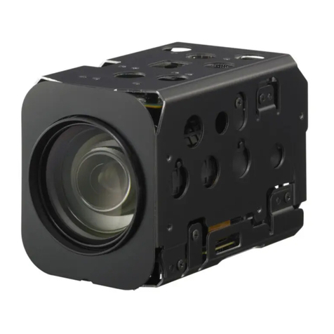
4K UHDTV CMOS
AF ZOOM Color Camera Module
DCC-4KNDI
Product Specification
& Operational Manual
(Preliminary)
CIS Corporation
For More Information Please Call Aegis Electronic Group, Inc. *CA- (760) 729-2026 AZ- (480) 635-8400 * [email protected] * http://www.aegis-elec.com
Aegis Electronic Group
www.aegiselect.com
Rev.905-0235-Z2
Table of Contents
Handling Precautions .............................................................................................................................................. 1
Camera Handling Precautions ....................................................................................................................... 1
Restrictions on Applications .......................................................................................................................... 1
Disclaimers (Exception Clause) ..................................................................................................................... 1
Product Outline ...................................................................................................................................................... 2
Features ...................................................................................................................................................... 2
Accessories ................................................................................................................................................. 2
Specifications ......................................................................................................................................................... 3
General Specifications .................................................................................................................................. 3
External Connectors ..................................................................................................................................... 5
3.2.1. RJ-45 Connector ......................................................................................................................................... 5
3.2.2. DC Jack ..................................................................................................................................................... 5
3.2.3. Video Monitor Output ................................................................................................................................. 5
3.2.4. Line Input .................................................................................................................................................. 6
3.2.5. Pin Jack for Communication ........................................................................................................................ 6
3.2.6. Connector for External LED ......................................................................................................................... 7
3.2.7. DIP Switch ................................................................................................................................................. 7
Camera Functions .................................................................................................................................................. 8
Defective Pixels Correction ........................................................................................................................... 8
4.1.1
Defective Pixels Data Type ......................................................................................................................... 8
4.1.2
Details on Defective Pixels Data .................................................................................................................. 8
4.1.3
Notes for Defective Pixels Correction ........................................................................................................... 9
Camera Operation ................................................................................................................................................ 10
Serial Communication ................................................................................................................................ 10
5.1.1
Serial Communication Specification ........................................................................................................... 10
5.1.2
Serial Command List ................................................................................................................................ 12
5.1.3
Quick Reference Table for Gain Settings .................................................................................................... 25
5.1.4
Quick Reference Table for Shutter Settings ................................................................................................ 26
5.1.5
Quick Reference Table for Iris Settings ...................................................................................................... 27
5.1.6
How to Operate Camera with OSD Function .............................................................................................. 28
How to Operate Camera with HTTP............................................................................................................. 29
5.2.1
Web API Specification .............................................................................................................................. 29
5.2.2
Camera Related API ................................................................................................................................. 30
5.2.3
Network Related API ................................................................................................................................ 31
5.2.4
System related API .................................................................................................................................. 35
5.2.5
How to Operate Camera via Web Browser ................................................................................................. 36
How to Operate Camera with NDI
®
PTZ Control .......................................................................................... 36
Dimensions .......................................................................................................................................................... 37
Case for Indemnity (Limited Warranty) and Others ................................................................................................. 38
Product Warranty ....................................................................................................................................... 38
CMOS Defective Pixels ............................................................................................................................... 38
Product Support ........................................................................................................................................ 38
License of Use ........................................................................................................................................... 38
For More Information Please Call Aegis Electronic Group, Inc. *CA- (760) 729-2026 AZ- (480) 635-8400 * [email protected] * http://www.aegis-elec.com
Aegis Electronic Group
www.aegiselect.com

DCC-4KNDI Rev.905-0235-Z2
Handling Precautions
Camera Handling Precautions
□Do not use or store the camera module in dusty or humid places.
□Due to zoom lens structure itself, dust may reach the surface of the image sensor while zooming and could
have a bad influence on output images. Please make sure to embed the camera module into a fully dust-
proof chassis/casing.
□When building-in the camera module to your products, we highly recommend you to work in a clean
environment such as a clean room to avoid dust adhering around the image sensor.
□Do not apply excessive force, vibration, or static electricity that could damage the camera module. Please
handle camera module with care.
□Do not shoot direct images that are extremely bright (e.g., strong light source, sun, etc.). When extremely
strong light source was shot, smear or blooming may occur.
□When strong light irradiates the lens-barrel of the camera module, a leak of light could reach the surface of
the image sensor and its projection could appear on an output image. Therefore, please use the camera
module shielded from strong light irradiating other than the lens. Please make sure that a leak of light does
not affect your system with the camera module embedded.
□Refer to Chapter 3.2., “External Connectors” for connecting the camera module.
Improper connection may cause damages not only to the camera module but also to the connected devices.
□Confirm the mutual ground potential carefully before connecting the camera to monitors or computers.
Any AC leaks from the connected devices may cause damages or destroy the camera module.
□Make sure to take protection countermeasures against surge voltage when camera is in use with surge
voltage concerned to be applied to LAN cable connected.
□Do not apply excessive voltage. (Use only the specified voltage.) When using an AC adaptor, use only the
CIS optional AC adaptor. Unstable or improper power supply voltage may cause damages or malfunction of
the camera module and may cause a smoke, fire, and rupture.
□Air-cooling fan is equipped at the camera rear panel for cooling electronic components. Do not block the
opening of ventilation hole.
Our warranty does not apply to damages or defects caused by neglecting the instructions and precautions
explained in this manual.
Restrictions on Applications
□The camera module must not be used for any nuclear equipment or aerospace equipment with which
mechanical failure or malfunction could result in serious bodily injury or loss of human life.
□The camera must not be used under conditions or environments other than specified in this manual.
Disclaimers (Exception Clause)
CIS should not be liable for any damages or losses if;
・damages or losses are caused by earthquake, lightning strike, fire, flood, or other acts of God.
・damages or losses are caused by deliberate or accidental misuse by user, or failure to observe information
and instructions explained in this manual.
・damages or losses are caused by repair or modification conducted by user or any unauthorized party.
・deterioration of image quality is caused by dust adhered to image sensor area after shipment.
・deterioration of image quality is caused by scratches on image sensor and optical parts damaged by user.
For More Information Please Call Aegis Electronic Group, Inc. *CA- (760) 729-2026 AZ- (480) 635-8400 * [email protected] * http://www.aegis-elec.com
Aegis Electronic Group
www.aegiselect.com
DCC-4KNDI Rev.905-0235-Z2
Product Outline
DCC-4KNDI is a NDI
®
compatible 4K PoV camera with x18 auto focus zoom lens. Using a 1/1.8”, rolling shutter
CMOS image sensor, the camera outputs NDI
®
output signals corresponds to 3840 x 2160 or 1920 x 1080 with
60p/59.94p/50p/30p/29.97p/25p/24p/23.98p.
The addition of NDI
®
compatibility to its DCC-4KZM will greatly enhance its versatility by eliminating the use of SDI
cables and enabling a single Ethernet cable connection to the acquisition system, making it more mobile and easy to
control. This camera will neatly migrate into the advanced IP-based workflow made possible by NDI
®
technology.
*NDI
®
is a registered trademark of Vizrt Group
Features
□Complies with NDI
®
(Network Device Interface)
□Features CIS original ISP, “Clairvu
TM
” for superb imaging quality.
□Noise reduction function (2DNR and 3DNR).
□x18 auto focus zoom lens.
□Dimensions: (H) 68.5mm x (W) 68mm ×(D) 120.6mm (without projection)
□Controllable with Ethernet or RS-232C.
Accessories
□
Standard Accessory
Lens cap
□
Optional Accessory
AC adaptor (model name: 5V-5A-S2-A-A)
□
Software
※ CIS control software is provided for evaluation purpose only.
CIS should be held harmless for any damage arising from the use of this control software. The purpose of
this control software is restricted to the evaluation and testing of this product only, and is not intended for
commercial use by the customer. CIS will not customize the program nor provide the source code.
For More Information Please Call Aegis Electronic Group, Inc. *CA- (760) 729-2026 AZ- (480) 635-8400 * [email protected] * http://www.aegis-elec.com
Aegis Electronic Group
www.aegiselect.com
DCC-4KNDI Rev.905-0235-Z2
Specifications
General Specifications
Electrical Specifications
Pickup
device
Device type 1/1.8” color CMOS sensor
Unit cell Size 2.0µm (H) × 2.0µm (V)
Resolution 2160p:
1080p:
3840 (H) × 2160 (V)
1920 (H) × 1080 (V)
Aspect ratio 16 : 9
Video output format NDI
®
output Monitor output
3840×2160p 60fps
3840×2160p 59.94fps
3840×2160p 50fps
3840×2160p 30fps
3840×2160p 29.97fps
3840×2160p 25fps
3840×2160p 24fps
3840×2160p 23.98fps
1920×1080p 60fps
1920×1080p 59.94fps
1920×1080p 50fps
1920×1080p 30fps
1920×1080p 29.97fps
1920×1080p 25fps
1920×1080p 24fps
1920×1080p 23.98fps
1280×720p 60fps
1280×720p 59.94fps
1280×720p 50fps
1920×1080p 30fps
1920×1080p 29.97fps
1920×1080p 25fps
1920×1080p 24fps
1920×1080p 23.98fps
1280×720p 60fps
1280×720p 59.94fps
1280×720p 50fps
1920×1080p 30fps
1920×1080p 29.97fps
1920×1080p 25fps
1920×1080p 24fps
1920×1080p 23.98fps
Video format NDI
®
Sensitivity F4.0 (2000lx)
Minimum illumination 0.7 lx (Conditions: AGC+48dB, iris fully open, electric shutter OFF)
Gain variable range AGC : 0dB~+48 dB * Noises may be noticeable at high gain.
MANUAL : 0dB~+ 48dB
Shutter speed variable range AUTO : 1/13600s~1/23.98s (Set the upper and the lower limitation.
Minimum shutter speed varies depending on frame rate).
MANUAL : 1/13600s~1/23.98s
(Minimum shutter speed varies depending on frame rate).
White balance adjustment range AUTO: Standard, Outdoor, Fluorescent
MANUAL: Red Gain, Blue Gain, One Push
PRESET: Custom (Color temperature settings), Tungsten(3200K),
Daylight(5500K), Cloudy(6500K), Shade(8000K)
Auto exposure detection Average, Center-Weighted, Spot (1/256), Backlight Compensation
Flicker cancellation ON, OFF
Edge enhancement OFF, 1~7
Color correction Auto, Standard, Fluorescent Light, Tungsten Lamp
Saturation adjustment 0% (B/W) ~100% (typ.) ~200%
Cyan suppression adjustment 0~15
Color saturation suppression OFF, 1~7
Noise reduction OFF, 1~6
For More Information Please Call Aegis Electronic Group, Inc. *CA- (760) 729-2026 AZ- (480) 635-8400 * [email protected] * http://www.aegis-elec.com
Aegis Electronic Group
www.aegiselect.com
DCC-4KNDI Rev.905-0235-Z2
Electrical Specifications (continued)
Gamma Complies with BT.709 curve: Contrast -2, -1, 0, +1, +2
Complies with BT.2100 (HLG) curve
Dynamic range Low (for better SNR), Normal, High
Knee point OFF, 100%, 95%, 90%, 85%, 80%, 75%
Color gamut BT.709, BT.2020
Master Pedestal -100 ~ 0 (typ.) ~ +100
Pedestal (R,G,B) RGB independent, -100 ~ 0 (typ.) ~ +100
Color balance RGB independent, 0 ~ 100 (typ.) ~ 200
Audio Stereo line input (Gain setting: -34.5dB~+33.0dB)
Built-in lens x18 Auto focus zoom lens
f=6.6 ~ 120mm / maximum aperture F value 1.61 (wide) ~ 4.13 (tele)
Pixel defect correction (white spot) Corrected upon shipment. Supports user setting.
Camera preset settings 1, 2, 3, 4 (User can set four kinds of preset.)
Remote control communications Ethernet or RS-232C
Power requirements PoE+ (IEEE 802.3at)
AC adaptor input: DC 5V±5%
Power consumption 18W
Mechanical Specifications
Dimensions H:68.5mm W:68mm D:120.6mm (without projection)
Refer to Section 6. Dimensions.
Weight 500g
Environmental Specifications
Safety/Quality standards UL: Components used comply with UL.
RoHS: 2011/65/EU EN50581 (RoHS2)
Durability Vibration Acceleration : 3G
Frequency : 10~150 Hz
Direction : X, Y, and Z 3 directions
Testing time : 30 minutes each
Shock No malfunction after 10 times drop from 1m height on 6 surfaces, 3 edges
and 1 corner
Operation Guaranteed Temperature 0°C ~ +45°C
Humidity: 20 ~ 80%RH with no condensation
Storage Temperature -30 ~ +60°C
Humidity: 20 ~ 80%RH with no condensation
For More Information Please Call Aegis Electronic Group, Inc. *CA- (760) 729-2026 AZ- (480) 635-8400 * [email protected] * http://www.aegis-elec.com
Aegis Electronic Group
www.aegiselect.com
DCC-4KNDI Rev.905-0235-Z2
External Connectors
3.2.1. RJ-45 Connector
Model name: 7499511611A (Würth Elektronik)
Signal system: 1000Base-T / PoE+
Use PoE power supply that complies with IEEE 802.3 at 30W.
Use high quality LAN cable with CAT5e and over.
3.2.2. DC Jack
Model name: MJ-179PH (Marushin Electric Mfg. Co., Ltd.)
When you do not supply power via PoE, use this connector to supply power from an optional AC adaptor.
Do not connect the optional AC adaptor while supplying power by PoE.
5V/4A input, outer diameter φ5.5mm / inner diameter φ2.1mm.
Use only CIS optional AC adaptor (model name: 5V-5A-S2-A-A).
Issues associated with the use of a third party’s AC adaptor are out of warranty.
3.2.3. Video Monitor Output
Model name: 10118242-001RLF (Amphenol ICC)
Video format is 1920 x 1080 (30fps and under) or 1280 x 720 (50fps and over) in 8 bit.
Frame rate varies depending on camera settings. Audio signals are not supported.
RJ-45 connector
DC
j
ack
Pin jack for communications
Line in
p
ut
Video monitor output
Connector for
external LED x2
DIP switch
V
entilation hole of
air-cooling fan
For More Information Please Call Aegis Electronic Group, Inc. *CA- (760) 729-2026 AZ- (480) 635-8400 * [email protected] * http://www.aegis-elec.com
Aegis Electronic Group
www.aegiselect.com
DCC-4KNDI Rev.905-0235-Z2
3.2.4. Line Input
Model name: MJ-074N-R (Marushin Electric Mfg. Co., Ltd.)
Connectφ3.5mm, 3-pole stereo mini plug.
3.2.5. Pin Jack for Communication
Model name: MJ-069-R (Marushin Electric Mfg. Co., Ltd.)
Connect φ2.5mm, 4-pole plug.
Pin No. Signals
1 Line input (L)
2 Line input (R)
3 GND
Pin No. Signals
1 Test terminal. Do not connect.
2 RS-232C TX output
3 RS-232C RX input
4 GND
1
(
chi
p)
2
(
rin
g)
3
(
sleeve
)
1
(
chi
p)
2
(
rin
g)
3
(
rin
g)
4
(
sleeve
)
For More Information Please Call Aegis Electronic Group, Inc. *CA- (760) 729-2026 AZ- (480) 635-8400 * [email protected] * http://www.aegis-elec.com
Aegis Electronic Group
www.aegiselect.com
DCC-4KNDI Rev.905-0235-Z2
3.2.6. Connector for External LED
Model name: 53261-0271 (MOLEX)
3.2.7. DIP Switch
Model name: CHS-04TB1 (COPAL)
This is not for users to operate. Do not change initial settings.
Connector Pin No. Function
CN6
1 Connect cathode (-) of external LED_1.
2 Connect anode (+) of external LED_1.
CN7 1 Connect cathode (-) of external LED_2.
2 Connect anode (+) of external LED_2.
DIP-SW Setting mode
1 2 3 4
ON OFF OFF ON Camera normal operation
Other than the above Test mode
Camera stops operating normally.
5
V
330Ω
For More Information Please Call Aegis Electronic Group, Inc. *CA- (760) 729-2026 AZ- (480) 635-8400 * [email protected] * http://www.aegis-elec.com
Aegis Electronic Group
www.aegiselect.com
DCC-4KNDI Rev.905-0235-Z2
Camera Functions
Defective Pixels Correction
In addition to the correction of defective pixels data registered upon shipment, we provide a method to update the
defective pixels correction data. Please refer to Section 5.1.2, Serial Command List for details.
4.1.1 Defective Pixels Data Type
There are two types of defective pixels data.
Defective data registered at factory
Data registered upon shipment from our factory. These data cannot be over-written.
Defective data registered by user
Data registered by the user. These data can be over-written freely.
In case of H Flip and V Flip modes, coordinates of defective pixels are converted automatically with a shift of one
pixel. This is due to the image sensor specifications.
4.1.2 Details on Defective Pixels Data
Defective pixels data are stored and controlled per two vertically divided regions. Up to 128 points per region, which
makes it a total of 256 points, can be registered as user register data. There is an overlap of 32 pixels (width) between
the two regions, and the defective pixel coordinates in the overlapping area are registered to both regions. Please
refer to the below for the definition of region.
Area0 Area1
1936
1936
2160
3840
32
(0,0)
(3839,2159)
The coordinate system is based on the upper left origin. Each region is defined as;
Area 0: (0, 0) – (1935, 2159)
Area 1: (1904,0) – (3839,2159)
For example, if the defective pixel is at (1903,0), the data is registered only to region 0.
However, if the defective pixel is at (1904,0), the data is registered to both region 0 and 1.
For More Information Please Call Aegis Electronic Group, Inc. *CA- (760) 729-2026 AZ- (480) 635-8400 * [email protected] * http://www.aegis-elec.com
Aegis Electronic Group
www.aegiselect.com
DCC-4KNDI Rev.905-0235-Z2
4.1.3 Notes for Defective Pixels Correction
To save data registered or deleted by a defective pixels correction command (SU 200~203), execute Save
command (SU705).
Init command (SU 700) does not restore defective pixels correction data. Use SU 203 to delete all data.
Defective pixels correction data is not subject to Camera Setting Store/Load command (SU 100/101).
User cannot save the same defective points as factory setting data as user registered data. If the same
defective points as ex-factory data were detected, the camera ignores those points.
If users specify a pixel data with the same coordinates of ex-factory data, camera returns an error.
Please noted that the detected results may not always be the same due to temperature, noise, and other
conditions.
Neglecting the instruction may cause not only inappropriate pixel defect correction but also failure of getting
proper images.
For More Information Please Call Aegis Electronic Group, Inc. *CA- (760) 729-2026 AZ- (480) 635-8400 * [email protected] * http://www.aegis-elec.com
Aegis Electronic Group
www.aegiselect.com
DCC-4KNDI Rev.905-0235-Z2
Camera Operation
There are three kinds of methods to control the camera.
□Control via serial communication (RS-232)
All camera functions are supported.
□Control via HTTP
All camera functions are supported.
□Control by NDI
®
PTZ Control
Zoom and focus controls are supported.
Serial Communication
For network settings, please refer to Section 5.2 Operation by HTTP. “Serial Commands” are character strings to be
sent via serial communication.
5.1.1 Serial Communication Specification
(1) Please refer to the below for the serial communication settings.
Baud rate 9600bps (default), 38400bps, 115200bps
Data 8bit
Stop bit 1bit
Parity None
XON/XOFF No control
(2) Control code
・Text-based communication executes camera control. Only ASCII 0x20~0x7E, 0x0A(LF=¥n), 0x0D(CR=¥r)
must be used. Please do not to use other than these codes.
・CR(0x0D) and LF(0x0A) are regarded as linefeed code and represent termination. Either CR or LF is used as
linefeed code from host to camera. (CR is used as linefeed in the setting example (5) explained later). CR
LF is used as linefeed code from camera to host.
・By sending command, parameter and linefeed code from host to camera, user can change camera settings
and acquire camera setting parameters.
・There are two types of commands. One is SU command to send settings and instructions to the camera (“S”
for “Set”), and the other is GU command (“G” for “Get”) to obtain information from the camera. Function
changes according to the address.
Almost all addresses support both SU and GU commands. However, some addresses accept only SU or GU.
GU commands acquire values set with SU commands (with some exceptions).
Command Parameter 1 Parameter 2 (3, 4, ...) Function
SU Address Set value
(There may be more than one)
To change camera settings and instruct
execution.
GU Address None
(with some exceptions)
To obtain camera information such as set
values.
(3) Serial command protocol
・Linefeed code and “>” should output from the camera as a prompt.
・Commands are not case-sensitive.
・Separate between a command and a parameter by single space (0x20).
・From the head of the input character to the linefeed code is defined as a single serial command.
・Parameters with 0x are regarded as Hexadecimal, the one with 0b are regarded as Binary, and others are
For More Information Please Call Aegis Electronic Group, Inc. *CA- (760) 729-2026 AZ- (480) 635-8400 * [email protected] * http://www.aegis-elec.com
Aegis Electronic Group
www.aegiselect.com
DCC-4KNDI Rev.905-0235-Z2
regarded as Decimal.
・Parameters are analyzed from the head to identifiable letters. Some inappropriate letters are ignored and
some are regarded as errors.
・Please refer to “Section 5.1.2. Serial Command List” for details on address and data.
・Camera receives the returned command from the Host and echo it back. At this time, camera converts the
linefeed code (CR or LF) to CR LF and echo it back.
・SU command returns prompt when successful. GU command returns acquired data (including linefeed) and
prompt. When error occurs, both SU command and GU command return an error message starting with
“ERROR” (including linefeed) and prompt.
(4) Other specifications
・Commands specified per pixel (AF frame, cross line position, and defective pixels related commands) are
always specified by 3840 x 2160 coordinates regardless of video format settings.
(5) Setting examples
【Example of GU command】
To get information of the address 45 with GU command.
[Send] GU[sp]45[¥r]
[Returned value] GU[sp]45[¥r][¥n] [Echo back]
[Returned value] 100[¥r][¥n] [Acquired data + Linefeed]
[Returned value] [¥r][¥n] [Linefeed]
[Returned value] >[sp] [> and space]
【Example of SU command】
To set 30 to the address 45 with SU command.
[Send] SU[sp]45[sp]30[¥r]
[Returned value] SU[sp]45[sp]30[¥r][¥n] [Echo back]
[Returned value] [¥r][¥n] [Linefeed]
[Returned value] >[sp] [> and space]
【Example of error occurred with SU command】
When setting 300 (out of setting range) to the address 45 with SU command.
[Send] SU[sp]45[sp]300[¥r]
[Returned value] SU[sp]45[sp]300[¥r][¥n] [Echo back]
[Returned value] [ERROR] Parameter Error [Error message] (Error message may be different).
[Returned value] [¥r][¥n] [Linefeed]
[Returned value] >[sp] [> and space]
[¥r]=CR(0x0D)
[¥n]=LF(0x0A)
[sp]=space (0x20)
For More Information Please Call Aegis Electronic Group, Inc. *CA- (760) 729-2026 AZ- (480) 635-8400 * [email protected] * http://www.aegis-elec.com
Aegis Electronic Group
www.aegiselect.com
DCC-4KNDI Rev.905-0235-Z2
5.1.2 Serial Command List
Video Format
Function Address Setting Value Initial
Value Description
Video Format 1
0: 3840×2160p 60fps
1: 3840×2160p 59.94fps
2: 3840×2160p 50fps
3: 3840×2160p 30fps
4: 3840×2160p 29.97fps
5: 3840×2160p 25fps
6: 3840×2160p 24fps
7: 3840×2160p 23.98fps
8: 1920×1080p 60fps
9: 1920×1080p 59.94fps
10: 1920×1080p 50fps
11: 1920×1080p 30fps
12: 1920×1080p 29.97fps
13: 1920×1080p 25fps
14: 1920×1080p 24fps
15: 1920×1080p 23.98fps
0
This is to set NDI® video output format.
Monitor output becomes the same frame rate,
which is 1280x720 with over 50fps, and 1920
x 1080 with under 30fps.
AE related
Function Address Setting Value Initial
Value Description
Gain Mode 2 0: Manual
1: Auto 1 This is to set gain control mode.
Gain Value 3
Magnification×0x10000
Setting range: 1~approx.251
(0x10000~0xFB304B)
0x10000
(65536)
This is to set gain value when gain mode is
Manual. (*1)
e.g.) To set x2 (approx. 6dB): SU 3 0x20000
※ Please Refer to Section 5.1.3. Quick Reference
Table for Gain Settings.
Gain Max Value 4
Magnification×0x10000
Setting range: 1~approx.251
(0x10000~0xFB304B)
0x200000
(2097152)
This is to set the maximum gain value when gain
mode is Auto. (*1)
※Please refer to Section 5.1.3. Quick Reference
Table for Gain Settings.
Shutter Mode 5 0: Manual
1: Auto 1 This is to set shutter control mode.
Shutter Value 6
Exposure time [s]×0x100000
Setting range:
1/13600~1/23.98s
(0x4D~0xAAD6)
0x4444
(17476)
1/60s
This is to set shutter value (exposure time) when
shutter mode is Manual. (*1)
Shorter value than 1 frame length must be set.
For example, when video format is 60fps, the
maximum shutter value will be 0x4444 (1/60s)
※Please refer to Section 5.1.4 Quick Reference
Table for Shutter Settings.
For More Information Please Call Aegis Electronic Group, Inc. *CA- (760) 729-2026 AZ- (480) 635-8400 * [email protected] * http://www.aegis-elec.com
Aegis Electronic Group
www.aegiselect.com

DCC-4KNDI Rev.905-0235-Z2
AE related (continued)
Function Address Setting Value Initial
Value Description
Shutter Limit 7
The 1st Parameter: Max value
Exposure time [s]×0x100000
Setting range:
1/13600~1/23.98s
(0x4D~0xAAD6)
0x4444
(17476)
1/60s
This is to set shutter variable range when shutter
mode is Auto. (*1)
Shorter value than 1 frame length must be set.
Max<Min is invalid.
e.g.) To set Max=1/60s, Min=1/8000s:
SU 7 0x4444 0x83
※Please refer to Section 5.1.4 Quick Reference
Table for Shutter Settings
The 2nd Parameter: Min value
Exposure time [s]×0x100000
Setting range:
Same as Max value
0x4D
(77)
1/13600s
Iris Mode 61 0: Manual
1: Auto 1 This is to set iris control mode.
Maximum
Aperture 63 None None
This is to acquire the current maximum aperture
F value. (GU only).
F value varies depending on zoom position.
Aperture Value 64 0: Close
0x800(F22.6)~0x62C30(F1.61)
0x62C30
(404528)
This is to set aperture value when Iris Mode is
Manual (*1).
Calculates aperture value with F value.
Aperture Value = 0x100000 / (F value x F value)
e.g.) To set F4.0: SU 64 0x10000
Please refer to Section 5.1.5 Quick Reference
Table or Iris Settings.
Aperture Limit 65
The 1st Parameter: Max value
0x800~0x62C30
0x62C30
(404528)
This is to set variable range of aperture value
when Iris Mode is Auto. (*1)
Max < Min is invalid.
e.g.) To set Max=F2.0, Min=F8.0;
SU 65 0x40000 0x4000
The 2nd Parameter: Min value
0x800~0x62C30
0x800
(2048)
Metering Mode 8
0: Average
1: Center-Weighted
2: Spot
3: Backlight Compensation
1 This is to set metering mode.
Spot Block 9
The 1st Parameter: X value: 0~15 7 This is to set X, Y, W, and H values for Spot
metering.
X: Far left of metering field Block, X coordinate
Y: Top of metering field Block, Y coordinate
W: Width of metering field (Block number)
H: Height of metering field (Block number)
e.g.) Execute SU 9 6 7 4 2 to set 4x2 block from
the coordinate (6, 7).
The 2nd Parameter: Y value: 0~15 7
The 3rd Parameter: W value: 1~16 2
The 4th Parameter: H value: 1~16 2
AE Speed 10 0~15 10 This is to set AE convergence speed.
For More Information Please Call Aegis Electronic Group, Inc. *CA- (760) 729-2026 AZ- (480) 635-8400 * [email protected] * http://www.aegis-elec.com
Aegis Electronic Group
www.aegiselect.com
DCC-4KNDI Rev.905-0235-Z2
AE related (continued)
(*1)Note that in some cases, the specified values may not be reflected due to the physical limitation of the lens. One such
instance is with the iris control, whereby the maximum F value is determined by the zoom position of the lens, and thus,
depending on the zoom position of the lens, the actual F value can vary from the theoretical F value specified by the iris
setting parameter. Confirm the actual control values with Current Gain, Current Shutter, and Current Aperture commands.
Function Address Setting Value Initial
Value Description
Exposure
Compensation
Value
11
0: -12dB
1: -11dB
...
12: 0dB
...
23: +11dB
24: +12dB
12
This is to set exposure compensation value.
Set value 12 is equivalent to 0dB.
Settable per 1dB.
Flicker Cancel 12 0: Off
1: On 0
This is to set ON/OFF of flicker cancel.
Valid only when video format is with 60fps,
59.94fps, 30fps, and 29.97fps.
Gain Value, Plus
Minus 13 -1: decrease 1dB
1 : increase 1dB None
This is to change gain value by ±1dB from the
current setting. (*1)
Valid when gain mode is Manual.
(Dedicated to SU)
Shutter Speed,
Plus Minus 14 -1: decrease 1step (1/4EV)
1 : increase 1step (1/4EV) None
This is to change shutter speed by ±1 step
(1/4EV) from the current value. When shutter
value decreases by 1step, shutter value becomes
bigger. (*1)
Valid when shutter mode is with Manual.
(Dedicated to SU)
Iris(F-number),
Plus Minus 15 -1: decrease 1step (1/4EV)
1 : increase 1step (1/4EV) None
This is to change F value of iris by ±1step
(1/4EV) from the current setting. When the
value reduces by 1step, aperture value becomes
bigger. (*1) Valid when iris mode is Manual.
(Dedicated to SU)
Current Gain 55 None None This is to acquire the current gain.
(Dedicated to GU) (*1)
Current Shutter 56 None None This is to acquire the current shutter value.
(Dedicated to GU) (*1)
Current
Aperture 57 None None
This is to acquire the current aperture (iris)
value.
(Dedicated to GU) (*1)
For More Information Please Call Aegis Electronic Group, Inc. *CA- (760) 729-2026 AZ- (480) 635-8400 * [email protected] * http://www.aegis-elec.com
Aegis Electronic Group
www.aegiselect.com
DCC-4KNDI Rev.905-0235-Z2
WB related
Function Address Setting Value Initial
Value Description
WB Mode 20
0: Manual
1: Auto
2: Preset
1 This is to set White Balance (WB) mode.
WB Manual
Memory 21 0~4 0
This is to choose the memory to store setting values when
WB Mode is with Manual.
You can store 5 types (0~4) of setting values.
Manual Red Gain 22 100~1600 (%) 191 This is to set Red Gain when WB Mode is Manual.
Manual Blue Gain 23 100~1600 (%) 179 This is to set Blue Gain when WB Mode is Manual.
One Push Trigger 24
1: W×H
2: W/2×H/2
3: W/4×H/4
None
This is to execute One Push WB when WB mode is Manual.
Choose a detection range with setting values. If execution
of One Push WB is not properly processed, camera will return
Run Time Error. (Do not shield light to execute this
command). (Dedicated to SU)
WB Auto Func 25
0: Standard
1: Outdoor
2: Fluorescent
0 This is to choose operation when WB Mode is Auto.
WB Preset Func 26
0: Custom
1: Tungsten (3200K)
2: Daylight (5500K)
3: Cloudy (6500K)
4: Shade (8000K)
2 This is to choose operation when WB Mode is Preset.
WB Preset Temp 27 2500~15000(K) 5500 This is to set color temperature when WB Preset Func is
Custom.
WB LB Shift 28 -10~10 0 This is to set shift amount of WB gain to Black Direction.
WB CC Shift 29 -10~10 0 This is to set shift amount of WB gain to Green Magenta
direction.
Current Red Gain 58 None None This is to acquire the current Red Gain. (Dedicated to GU)
Current Blue Gain 59 None None This is to acquire the current Blue Gain. (Dedicated to GU)
For More Information Please Call Aegis Electronic Group, Inc. *CA- (760) 729-2026 AZ- (480) 635-8400 * [email protected] * http://www.aegis-elec.com
Aegis Electronic Group
www.aegiselect.com
DCC-4KNDI Rev.905-0235-Z2
Image Quality related
Function Address Setting Value Initial
Value Description
Detail 30 0: Off
1(Low)~7(High) 3 This is to set details.
Gamma 35
0: BT.709 -2
1: BT.709 -1
2: BT.709
3: BT.709 +1
4: BT.709 +2
5: HLG75
2
This is to set gamma type and contrast.
0~4 are the curves comply with BT.709.
Contrast changes in the range of -2 ~ +2.
5 is for HLG75 that means 75% output level is
regarded as 100% input level.
Knee 36
0: Off
1: 100%
2: 95%
3: 90%
4: 85%
5: 80%
6: 75%
4
This is to set knee point.
Valid except when Gamma is BT.709 and D-
range is Low.
Knee slope varies according to the selected
maximum D-Range.
Master Pedestal 37 -100~+100 0 This is to set Master pedestal.
Red Pedestal 38 -100~+100 0 This is to set Red pedestal.
Green Pedestal 39 -100~+100 0 This is to set Green pedestal.
Blue Pedestal 40 -100~+100 0 This is to set Blue pedestal.
Red Balance 41 0~200 100 This is to set Red balance.
Green Balance 42 0~200 100 This is to set Green balance.
Blue Balance 43 0~200 100 This is to set Blue balance.
D-Range 44
0: Low
Equivalent to 120% in BT.709
Invalid for HLG (Handled as
Normal)
1: Normal
Equivalent to 200% at BT.709
Equivalent to 600% at HLG
2: High
400% at BT.709
Equivalent to 1200% at HLG
1
This is to set Dynamic range.
When Low, both D range and sensitivity
decrease, but noise level becomes the lowest.
When High, the minimum gain value will be
limited to 0x20000. (Even with a lower value
setting, gain value becomes 0x20000.)
※ The D-range definition of BT.709 and HLG
are different, ref. below. (*2)
[BT.709]
100% output level (without Knee) is
regarded as 100% input level.
[HLG]
50% output level is regarded as 100% input
level.
(*2) The standard is IRE100% of when output range is set to the limited range (with super white).
For More Information Please Call Aegis Electronic Group, Inc. *CA- (760) 729-2026 AZ- (480) 635-8400 * [email protected] * http://www.aegis-elec.com
Aegis Electronic Group
www.aegiselect.com
DCC-4KNDI Rev.905-0235-Z2
Image Quality related (continued)
Function Address Setting Value Initial
Value Description
Color Saturation 45 0~200 100 This is to set color saturation.
Cyan Suppression 46 0~15 15 This is to set suppression for Cyan saturation.
Color Adjustment 47
The 1st Parameter: Selection of color
0: Magenta
1: Red
2: Yellow
3: Green
4: Cyan
5: Blue All 0
This is to set color adjustment values.
There are three kinds of adjustment items for
each 6 color, which makes it a total of 18
parameters for color adjustment.
e.g.) To set -3 to Cyan Hue
SU 47 4 0 -3
To execute GU, please specify the 1st
parameter and the 2nd parameter.
e.g.) To acquire adjustment value of Cyan
Hue
GU 47 4 0
The 2nd Parameter: Selection of item
to adjust
0: Hue
1: Saturation
2: Depth
The 3rd Parameter: Adjustment value
-20~20
Output Range 49
0: Limited range
(without super white)
1: Limited range
(with super white)
2: Full range
1
This is to set output range. Output range of
Y (brightness) and C (Color difference)
change as follows.
At 0: Y:16~235, C: 16~240
At 1: Y:16~254, C: 1~254
At 2: Y: 0~255, C: 0~255
Noise Reduction 50 0: Off
1 (Low)~6 (High) 3
This is to set the level of noise reduction.
With level 1, only 2DNR is effective.
With level 2 and over, both 2DNR and 3DNR
are effective. (*3)
Color Correction 52
0: Auto
1: Standard
2: Fluorescent Light
3: Tungsten Lamp
0 This is to set color correction.
Color
Suppression 53 0: Off
1 (Low)~7(High) 0 This is to set color suppression.
Color Space 54 0: BT.709
1: BT.2020 0 This is to set color gamut.
(*3) When noise reduction level goes higher, residual images may become evident.
Noisy video source could result in higher bandwidth after image compression, which could result in drop of video frames.
In such cases, please reduce the noise level by reducing gain and/or increasing noise reduction level.
For More Information Please Call Aegis Electronic Group, Inc. *CA- (760) 729-2026 AZ- (480) 635-8400 * [email protected] * http://www.aegis-elec.com
Aegis Electronic Group
www.aegiselect.com
DCC-4KNDI Rev.905-0235-Z2
Lens Control related
Function Address Setting Value Initial
Value Description
Zoom Drive 66
The 1st Parameter: Move mode
0: To specify the absolute zoom position
1: To specify the relative zoom position
2: To specify direction for zoom to move
0
This is to move the zoom lens.
There are three kinds of way to specify.
Select with move mode.
When move mode is 0 and 1, lens moves
to the specified position and stops.
When move mode is 2, lens starts moving
by specifying -1 or 1, and stops with 0.
(It also stops when lens reaches the wide
edge or the tele edge).
This command is non-blocking so that it
returns prompt before completing its
movement.
(*4)
The 2nd Parameter:
【When move mode is 0】
0 (wide edge)~1024 (tele edge)
【When move mode is 1】
-1024 (wide)~1024 (tele)
【When move mode is 2】
-1: Move to wide direction
1: Move to tele direction
0: Stop
0
The 3rd Parameter: Move speed
0~64 64
Focus Drive 67
The 1st Parameter: Move mode
0: To specify absolute focus position
1: To specify relative focus position
2: To specify direction for focus to move.
0
This is to move focus lens when focus
mode is Manual.
There are three kinds of way to specify.
Select with move mode.
When move mode is 0 and 1, lens moves
to the specified position and stops.
When move mode is 2, lens starts moving
by specifying -1 or 1, and stops with 0.
(It also stops when lens reaches the far
edge or the near edge).
This command is non-blocking so that it
returns prompt before completing its
movement.
(*4)
The 2nd Parameter:
【When move mode is 0】
0 (far edge)~3584 (near edge)
【When move mode is 1】
-3584 (far side)~3584 (near side)
【When move mode is 2】
-1: Move to far direction
1: Move to near direction
0: Stop
0
The 3rd Parameter: Move speed
0~64 64
Focus Mode 68 0: Manual
1: Auto 1 This is to set focus control mode.
(*5)
Focus One
Push
Trigger
69 1 (Fixed) None
This is to execute One Push AF when focus
mode is Manual.
This command is non-blocking so that it
returns prompt before completing its
movement.
With GU 69, user can acquire operating
status of One Push AF.
(0=stop, 1=in operation).
(*4) If user changes video format while the lens is moving (zooming), the lens stops movement.
(*5): In AF mode, the AF may lose focus when abrupt zoom in/out is applied.
For More Information Please Call Aegis Electronic Group, Inc. *CA- (760) 729-2026 AZ- (480) 635-8400 * [email protected] * http://www.aegis-elec.com
Aegis Electronic Group
www.aegiselect.com
Table of contents
Other CIS CCTV Camera manuals

CIS
CIS VCC-HD3N Quick start guide

CIS
CIS VISION:mini VCC-F22S29ACL Quick start guide

CIS
CIS DCC-HD3 Quick start guide

CIS
CIS VCC-SXCL3R Quick start guide

CIS
CIS Vision:mini VCC-F22U29APCL Quick start guide

CIS
CIS VCC-HD5 Quick start guide

CIS
CIS DCC-4KZM Quick start guide

CIS
CIS VISION:mini VCC-F22S29APCL Quick start guide

CIS
CIS VCC-F32U29CL Installation instructions

CIS
CIS VCC-HD1000A Quick start guide