CIS VCC-FC21U19OP Quick start guide

VCC-FC21U19OP Rev. 900-766-30-00
©2014 CIS Corporation. All rights reserved.
Optical I/F
UXGA Resolution CMOS
Color (RAW) Camera
VCC-FC21U19OP
Product Specification
& Operational Manual
CIS Corporation
English

VCC-FC21U19OP Rev. 900-766-30-00
©2014 CIS Corporation. All rights reserved.
2
Table of Contents
PAGE
1. Handling Precautions...........................................................................................................................................3
2. Product Outline...................................................................................................................................................4
3. Bundled Items ....................................................................................................................................................4
3.1. Standard Bundled Items ...........................................................................................................................4
3.2. Optional Items.........................................................................................................................................4
3.3. Free Software ..........................................................................................................................................4
3.4. Packaging................................................................................................................................................4
4. Specifications .....................................................................................................................................................5
4.1. General Specifications ..............................................................................................................................5
4.2. Camera Output Signal Specification ...........................................................................................................7
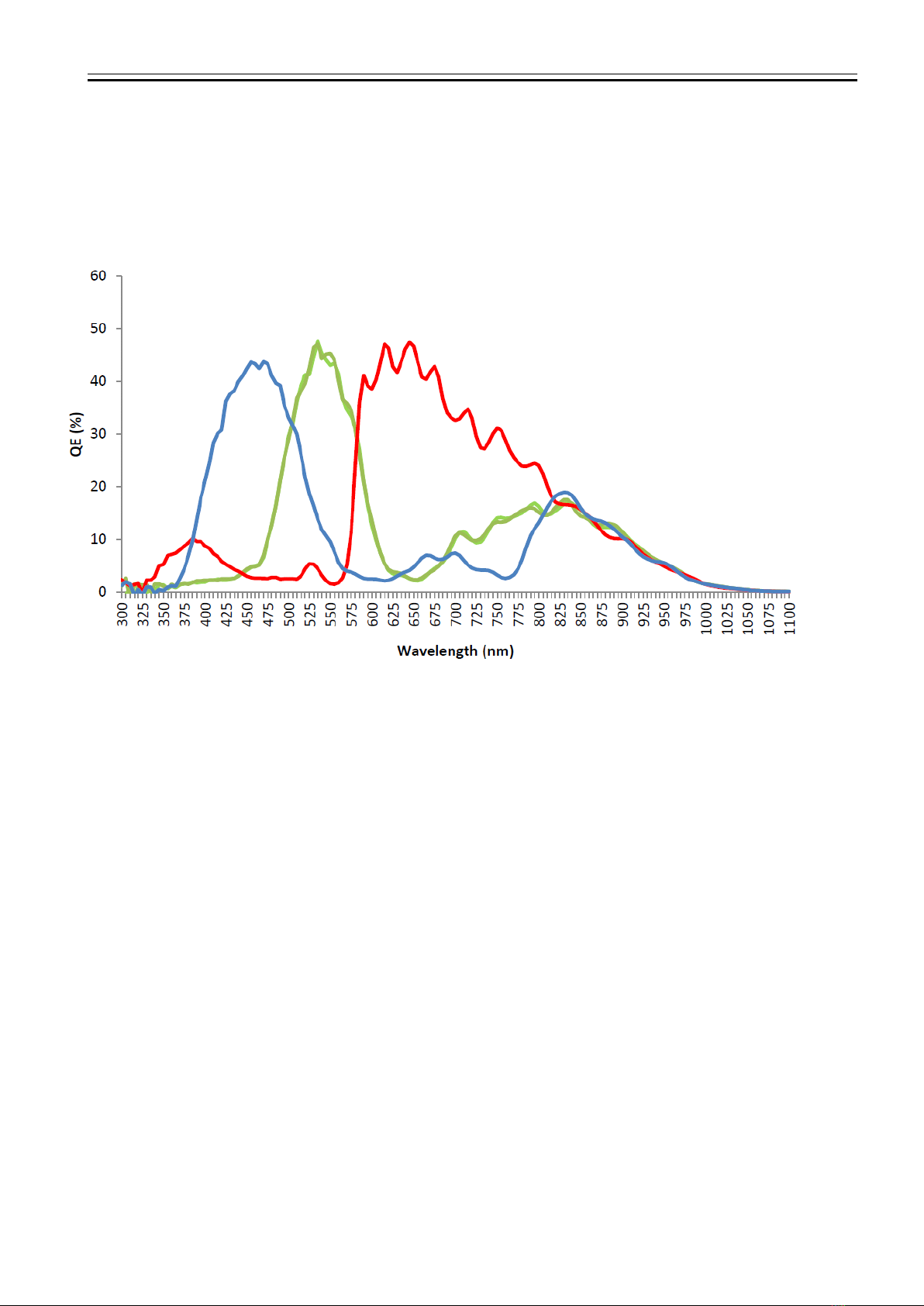
4.3. Spectral Response (Representative Value) ..................................................................................................8
4.4. Video Output Format ................................................................................................................................9
5. Function Settings .............................................................................................................................................. 10
6. External Connector Pin Assignment..................................................................................................................... 13
6.1. 6 Pins Circular Connector HR10-7R-6PA (HIROSE) Equivalent ................................................................. 13
6.2. Optical Module Connector AFBR-57D9AMZ(AVAGO) ................................................................................. 14
6.3. Optical LINK LED ................................................................................................................................... 14
7. Timing Chart .................................................................................................................................................... 15
7.1. Horizontal Synchronous Signals Timing (2Tap Base Configuration mode: 63fps) ......................................... 15
7.2. Vertical Synchronous Signals Timing (2Tap Base Configuration Mode: 63fps)............................................... 15
7.3. Horizontal Synchronous Signals Timing (4Tap Medium Configuration Mode: 126fps) *Initial Setting .............. 16
7.4. Vertical Synchronous Signals Timing (4Tap Medium Configuration Mode: 126fps) ........................................ 16
7.5. Fixed Trigger Shutter Mode ..................................................................................................................... 17
7.6. Pulse Width Trigger Shutter Mode............................................................................................................ 18
8. Partial Scan Mode ............................................................................................................................................. 19
9. Remote Communication Function ....................................................................................................................... 21
10. Initial Settings .................................................................................................................................................. 22
11. CMOS Optical Axis Accuracy............................................................................................................................... 23
12. Dimensions ...................................................................................................................................................... 24
13. Cases for Indemnity (Limited Warranty) .............................................................................................................. 25
14. CMOS Pixel Defect ............................................................................................................................................ 25
15. Product Support................................................................................................................................................ 25

VCC-FC21U19OP Rev. 900-766-30-00
©2014 CIS Corporation. All rights reserved.
3
1. Handling Precautions
The camera module must not be used for any nuclear equipments or aerospace equipments with which
mechanical failure or malfunction could result in serious bodily injury or loss of human life. Our warranty does
not apply to damages or defects caused by irregular and/or abnormal use of the product.
Please observe all warnings and cautions stated below.
Our warranty does not apply to damages or malfunctions caused by neglecting these precautions.
Do not use or store the camera in the dusty or humid places.
Do not apply excessive force, vibration or static electricity that could damage the camera. Handle the
camera with caution.
Do not shoot direct images that are extremely bright (e.g., light source, sun, etc.), and when camera is not in
use, please put the lens cap on. When extremely strong light source is shot, smear or blooming may occur.
Follow the instructions in Chapter 6, “External Connector Pin Assignment”for connecting the camera module.
Improper connection may cause damages not only to the camera module but also to the connected devices.
Confirm the mutual ground potential carefully before connecting the camera to other equipments. AC leaks
from the connected devices may cause damages or destroy the camera.
Do not apply excessive voltage. (Use only the specified voltage.) Unstable or improper power supply
voltage may cause damages or malfunction of the camera assembly.
The voltage ripple of camera power DC+12V±10% shall be within ±50mV. Improper power supply voltage
may cause noises on the video signals.
The rising time of camera power supply voltage shall be less than +10V, Max 60ms. Please avoid noises like
chattering when rising.
Precautions to observe when using partial mode.
At vertical partial scan mode, the smaller the value of read-out lines is set, the faster the camera exposure output
speed goes, and the more the power consumption is required at the same time.
Power requirement when the minimum read-out line is set with partial scan will be approx 5.0W, while the one with
full frame scan will be approx.4.5W. Naturally, heat of the camera will be increased.
Especially when the read-out line is set in the range of 50 lines to 1 line, heat dissipation is recommended to install the
camera.
Installation recommended.
・Install the camera to the place with ambient temperature under 40 ℃.
・Install the camera to a metallic component.
10 4020 30 50
10
11
12
[V]
Voltage Rising Time [ms ]
9
8
7
60 70
Power Supply Voltage

VCC-FC21U19OP Rev. 900-766-30-00
©2014 CIS Corporation. All rights reserved.
4
2. Product Outline
This is to describe VCC-FC21U19OP, UXGA resolution, Opt:C-LINK (Optical) I/F Color (RAW) CMOS Camera. 2M pixels CMOS
sensor with diagonal length 12.775mm is utilized. Entire pixels can be read out within 1/126s at Medium Configuration
output.
All specifications contained herein are subject to change without prior notice. Reproduction in whole or in part is prohibited.
Features
□Global shutter CMOS sensor
□Opt:C-LINK Base Configuration and Medium Configuration are supported.
□Fixed trigger shutter mode, pulse width trigger shutter mode
□Enables 150m long-distance transmission with optical fiber cable.
□No radio interference or grand noise concerned owing to optical fiber cable connection.
□Please refer to the below for full frame rates and video output format.
3. Bundled Items
3.1. Standard Bundled Items
□Camera module, FC21U19OP
3.2. Optional Items
□TBD
3.3. Free Software
□CIS camera control software for evaluation purpose only is downloadable via our web.
3.4. Packaging
□Individual carton
□Master carton (20pcs/carton)
* Master carton may change depends on the quantity to be shipped per delivery.
2Tap Base Configuration Mode
63fps
8bit/10bit
4Tap Medium Configuration Mode
126fps
8bit/10bit
Initial setting:4Tap Medium Configuration (126fps, 8bit)

VCC-FC21U19OP Rev. 900-766-30-00
©2014 CIS Corporation. All rights reserved.
5
4. Specifications
4.1. General Specifications
(1) Pickup Device
Device Type
Diagonal Length 12.775mm, Global Shutter type, Color CMOS
Effective pixel number
2048(H) x 1088(V)
11.264
5.984
12.775
(単位:mm)
Unit cell size
5.5μm(H) x 5.5μm(V)
Image Circle
φ12.775mm
(2) Video Output Frequency
Pixel Clock
72 MHz
2Tap
Base Configuration Mode:
Horizontal frequency:
69.768 kHz
Horizontal clock
1032 CLK
Vertical frequency:
63.195 Hz
Scanning lines
1104 H
4Tap
Medium Configuration Mode:
Horizontal frequency:
139.534 kHz
Horizontal clock
516 CLK
Vertical frequency:
126.390 Hz
Scanning lines
1104 H
(3) Sync. System
Internal Sync. System.
(4) Video Output
2Tap Base Configuration
4Tap Medium Configuration (Initial Setting)
(5) Optical Connector
LC duplex connector
Rated optical module:8Gb/s Optical wavelength 850nm
Transmission band:6.125Gb/s
AFBR-57D9AMZ(AVAGO)
(6) Length of Optical Fiber
Cable
Max. 150m
(7) Resolution
10888 TV Lines
(8) Output Format
Sensor AD
10bit
Opt:C-LINK output
8bit / 10bit Color (RAW) output.
(9) Sensitivity
F4.0 2000lx (at Shutter speed 1/126s (OFF), Gain 0dB, and Medium Configuration mode)
(10) Minimum illumination
F1.4 50lx (at Shutter speed 1/126s (OFF), Gain +12dB, and Medium Configuration mode)
(11) Dust or stains in optical
system
No dust or stain shall be detected on the testing screen with setting the camera aperture at F16.
(12) Power requirements
DC+12V±10% 6pins Circular Connector
(13) Power consumption
4.5W (4Tap Medium Configuration mode, Full frame scan output): Initial setting.
5.0W (4Tap Medium Configuration mode, Partial scan 10 lines output)
(14) Dimensions
Refer to overall dimension drawing. (H:29mm W:43mm D:55mm excluding projection)
(15) Weight
Approx. 125g
(16) IR Cut Filter
With
(17) Lens mount
C Mount * Refer to overall dimension drawing.
(18) Optical axis accuracy
Refer to drawing for CMOS Optical Axis Accuracy.
(19) Gain variable range
0dB ~+12dB (Guaranteed range)
(20) White Balance Adjustment
2800~9000K (Manual White Balance) (Guaranteed range)
(21) Shutter speed variable
range
OFF ~1/40000s
(22) Trigger shutter mode
Fixed Shutter Trigger Mode/ Pulse Width Shutter Trigger Mode
(23) Partial Scan
Full Frame Scan ~1 line (1 line / step)

VCC-FC21U19OP Rev. 900-766-30-00
©2014 CIS Corporation. All rights reserved.
6
(24) Safety/Quality standards
UL:
Conform to UL Standard including materials and others.
CE:
EN55022:2010 Class A for Emission
EN61000-6-2:2005 for Immunity
RoHS:
Conform to RoHS.
FCC:
To be applied to FCC Class A digital Device
This device complies with Part 15 of the FCC Rules. Operation is subject to the
following two conditions: (1) this device may not cause harmful interference, and
(2) this device must accept any interference received, including interference that
may cause undesired operation.
(25) Durability
Vibration
Acceleration
: 98m/s2(10G)
Frequency
: 20~200 Hz
Direction
: X,Y, and Z 3 directions
Testing time
: 120min for each direction
Shock
No malfunction shall be occurred with 980m/s2(100G) for ±X,±Y, and ±Z,
6 directions. (without package)
(26) Operation Environment
Temperature
Performance guaranteed temperature: 0℃~+40℃
Camera operation guaranteed temperature: -5℃~+45℃
※All the specifications specified in this manual is guaranteed under performance
guaranteed temperature.
※All the camera functions operate normally under operation guaranteed
temperature.
Humidity
RH 20~80% with no condensation.
(27) Storage Environment
Temperature
-25℃~+60℃
Humidity
RH 20~80% with no condensation.

VCC-FC21U19OP Rev. 900-766-30-00
©2014 CIS Corporation. All rights reserved.
7
4.2. Camera Output Signal Specification
(1) Video output data
Effective Video Output
2048(H) × 2048(V)
At full frame scan mode
(2) Sync. Signal output
FVAL
Pin No.3
6pins Circular Connector
(LVTTL Output)
Opt:C-LINK Output
Optical Pulse
Pin No.4
LVAL
Pin No.5
LVAL
FVAL
DVAL
SP
Optical Pulse
(3) Camera Control
Signals input
CC2・CC3・CC4
Opt:C-LINK Input
(4) Trigger Input
Polarity
Positive/Negative Selectable
Polarity is selectable
with Address 011
Pulse Width
1HD (min.) ~Approx. 2 frames
・2Tap Base Configuration mode
: 1HD (14.333us)
・4Tap Medium Configuration mode
: 1HD (7.167us)
Functionally, no upper limitation is set but noises such as dark
noises and shadings might be noticeable at long time exposure.
Trigger Input
:CC1
Camera Link input (LVDS)
:Pin No.2
6pins Circular Connector (LVTTL)
(5) Serial Communication
SerTC (Serial to Camera)
Opt:C-LINK input
SerTFG (Serial to Frame Grabber)
Opt:C-LINK output
(6) Video Signals
White Clip Level
At Digital 10bit
At Digital 8bit
: 3FFh
: FFh
Setup Level
At Digital 10bit
At Digital 8bit
: 004±004h
: 01±01h
(Condition: Gain 0dB)
Dark Shading
At Digital 10bit
At Digital 8bit
: Both horizontal and vertical
should be under ±00Fh.
: Both horizontal and vertical
should be under 03h.
(Condition: Gain 0dB)
※2 seconds shall be waited after turning on power to get the camera operate properly.

VCC-FC21U19OP Rev. 900-766-30-00
©2014 CIS Corporation. All rights reserved.
8
4.3. Spectral Response (Representative Value)
* Lens characteristics and luminous source characteristics are not considered.

VCC-FC21U19OP Rev. 900-766-30-00
©2014 CIS Corporation. All rights reserved.
9
4.4. Video Output Format
(1) 2Tap Base Configuration Mode : 63fps
(2) 4Tap Base Configuration Mode : 126fps (Initial Setting)
・・・
~
~~
~
1088 Line
2048pixel
1
GB
2
・・・
~
~~
~
1088 Line
2048pixel
GBGB
1 2 3 4

VCC-FC21U19OP Rev. 900-766-30-00
©2014 CIS Corporation. All rights reserved.
10
5. Function Settings
(Camera functions can be set with serial communications.)
Function
Address
Data
Gain
001
0:
0
dB : Fixed Gain
1:
+
3
dB : Fixed Gain
2:
+
6
dB : Fixed Gain
3:
+
12
dB : Fixed Gain
4:
Manual Gain: over 0~+12dB (Refer to Address 032 and 033.)
Shutter
002
2Tap Mode
4Tap Mode
0:
1/63s(OFF)
1/126s(OFF)
1:
1/126s
1/126s(OFF)
2:
1/250s
1/250s
3:
1/350s
1/350s
4:
1/500s
1/500s
5:
1/750s
1/750s
6:
1/1000s
1/1000s
7:
1/2500s
1/2500s
8:
1/5000s
1/5000s
9:
1/7500s
1/7500s
10:
1/10000s
1/10000s
11:
1/12000s
1/12000s
12:
1/16000s
1/16000s
13:
1/20000s
1/20000s
14:
1/30000s
1/30000s
15:
1/30000s
1/40000s
16:
Manual Shutter (Refer to Address 036 and 037.)
White Balance
003
0:
Through
1:
3200K
2:
Through
3:
Through
4:
Manual White Balance
(Refer to Address 046&047, 048&049, and 050&051)
Trigger Shutter Mode
004
0:
Normal Shutter Mode (Trigger OFF)
1:
Fixed Trigger Shutter Mode (Shutter speed can be set with address 002.)
2:
Pulse Width Trigger Shutter Mode
(Shutter speed can be set with trigger pulse width.)
Trigger Polarity
011
0:
Positive
1:
Negative
Trigger Input
012
0:
Opt:C-LINK (CC1) input
1:
6pins connector (Pin No.2) input
Output Data Selection
013
0:
8bit Output
1:
10bit output
Partial Scan Mode
015
0:
Full Frame Scan Mode
1:
Partial Scan Mode
Output image flip vertical
021
0:
Normal
1:
Flip Vertical
Gain CC Control ON/OFF
023
0:
OFF
1:
ON (Gain and WB can be controlled via CC2, CC3, and CC4.)

VCC-FC21U19OP Rev. 900-766-30-00
©2014 CIS Corporation. All rights reserved.
11
Function
Address
Data
Table Selection for Gain CC Control
024
0~7:
The following is the matrix of CC2, CC3, CC4, and the table.
CC2
CC3
CC4
0:
L
L
L
1:
H
L
L
2:
L
H
L
3:
H
H
L
4:
L
L
H
5:
H
L
H
6:
L
H
H
7:
H
H
H
Table Read/Write
for Gain CC Control
025
0:
Nop
1:
Table Read
2:
Table Write
Manual Gain (Address 032 & 033),
Manual WB R (Address 046 & 047),
Manual WB B (Address 048 & 049),
Manual WB G (Address 050 & 051),
are written into the table specified with Address 024.
3:
Clear Table
Baud Rate
030
0:
9600bps (fixed)
Camera Mode
031
0, 1:
4Tap Medium Configuration Mode (126fps)
2:
2Tap Base Configuration Mode (63fps)
Manual Gain
032&033
0~767:
0:0dB ~767:+12dB
Manual Shutter
036&037
0~1087:
2Tap mode: Shutter Speed =18.49us + (1088 - (036&037))×14.333us
Min. value 0: 15.613ms (1/63s), Max. value 1087: 32.823us (1/30000s)
4Tap mode: Shutter Speed =18.49us + (1088 - (036&037))×7.167us
Min. value 0: 7.816ms (1/126s), Max. value 1087:25.657us (1/40000s)
※Set the data of the address 002 to 016.
Manual White Balance R
046&047
0~767:
0:0dB ~767:+12dB
※Set the data of the address 003 to 004.
Manual White Balance B
048&049
0~767:
0:0dB ~767:+12dB
※Set the data of the address 003 to 004.
Manual White Balance G
050&051
0~767:
0:0dB ~767:+12dB
※Set the data of the address 003 to 004.
Cursor Indication ON/OFF
058
0:
OFF
1:
ON
Cursor X Address
061&060
0~2047:
Cursor Y Address
063&062
0~2047:

VCC-FC21U19OP Rev. 900-766-30-00
©2014 CIS Corporation. All rights reserved.
12
Function
Address
Data
Partial scan start position 1
064&065
0~1087:
Partial scan start position 2
066&067
0~1087:
Partial scan start position 3
068&069
0~1087:
Partial scan start position 4
070&071
0~1087:
Partial scan start position 5
072&073
0~1087:
Partial scan start position 6
074&075
0~1087:
Partial scan start position 7
076&077
0~1087:
Partial scan start position 8
078&079
0~1087:
※Set the data of the address 015 to 001.
Partial scan effective line numbers 1
080&081
1~1088:
Set 0 when not in use.
Partial scan effective line numbers 2
082&083
1~1088:
Set 0 when not in use.
Partial scan effective line numbers 3
084&085
1~1088:
Set 0 when not in use.
Partial scan effective line numbers 4
086&087
1~1088:
Set 0 when not in use.
Partial scan effective line numbers 5
088&089
1~1088:
Set 0 when not in use.
Partial scan effective line numbers 6
090&091
1~1088:
Set 0 when not in use.
Partial scan effective line numbers 7
092&093
1~1088:
Set 0 when not in use.
Partial scan effective line numbers 8
094&095
1~1088:
Set 0 when not in use.
※Set the data of the address 015 to 001.
Initial Settings
126
Input 083 to set the camera back to the initial settings.
Data Save
127
Input 083 to save the data to EEP-ROM.
※The data set with 2 Byte shall be set with High Byte (even address) first, then set with Low Byte (odd address).
The camera rewrites the internal resister when receiving Low Byte.

VCC-FC21U19OP Rev. 900-766-30-00
©2014 CIS Corporation. All rights reserved.
13
6. External Connector Pin Assignment
6.1. 6 Pins Circular Connector HR10-7R-6PA (HIROSE) Equivalent
Pin No.
1
Power IN (DC+12V)
2
Trigger Input
3
FVAL Output
4
Exposure Output
5
LVAL Output
6
GND

VCC-FC21U19OP Rev. 900-766-30-00
©2014 CIS Corporation. All rights reserved.
14
6.2. Optical Module Connector AFBR-57D9AMZ(AVAGO)
LC duplex Connector
6.3. Optical LINK LED
(1) Opt:C-LINK LINK LED ・・・ The LED is lit when connecting the camera and the frame grabber board.

VCC-FC21U19OP Rev. 900-766-30-00
©2014 CIS Corporation. All rights reserved.
15
7. Timing Chart
7.1. Horizontal Synchronous Signals Timing (2Tap Base Configuration mode: 63fps)
7.2. Vertical Synchronous Signals Timing (2Tap Base Configuration Mode: 63fps)
FVAL Out
1Frame = 1104H(15.824ms)
Effective Line : 1088H
Effective Line
DVAL Out
~
~
LVAL Out
~
~
Effective Line
~
~~
~
V Blanking : 16H
(Read Out Pulse)
Exposure Time( Address (036&037))
SP Out(Exposure Out)
1
0
8
8
1
0
8
8
1 1
1H = 14.333us
Video Out
~
~
~
~
10
H

VCC-FC21U19OP Rev. 900-766-30-00
©2014 CIS Corporation. All rights reserved.
16
7.3. Horizontal Synchronous Signals Timing (4Tap Medium Configuration Mode: 126fps) *Initial Setting
7.4. Vertical Synchronous Signals Timing (4Tap Medium Configuration Mode: 126fps)
FVAL Out
1Frame = 1104H(7.912ms)
Effective Line : 1088H
Effective Line
DVAL Out
~
~
LVAL Out
~
~
Effective Line
~
~~
~
V Blanking : 16H
(Read Out Pulse)
Exposure Time( Address (036&037))
SP Out(Exposure Out)
1
0
8
8
1
0
8
8
1 1
1H = 7.167us
Video Out
~
~
~
~
7
H

VCC-FC21U19OP Rev. 900-766-30-00
©2014 CIS Corporation. All rights reserved.
17
7.5. Fixed Trigger Shutter Mode
□This is the mode to start exposure with external input trigger signals, and set the exposure time with serial
commands.
□Trigger operation is H Sync. V-Sync Reset. The delay time (Exposure Time Delay) from detecting trigger edge in the
camera to starting exposure is max. 1HD.
□Triggers can be accepted even when outputting video signals. However, trigger signals to start the next video
output before completion of the prior video output signals cannot be accepted.
□Trigger input during exposure time should be ignored. (Refer to the below A).
Effective Line : 1088H
Effective Line
~
~
SP Out
(Exposure Out)
1
0
8
8
1
TRIG IN
(Read Out Pulse)
LVAL Out
FVAL Out
Video Out
DVAL Out
~
~
2
0
4
8
1
Effective Line
Exposure Time
(Trigger input ignore period)
Exposure Time Delay
(A)
TRIG Input EN
TRIG IN
SP Out
(Exposure Out)
2Tap Base Configuration Mode max 14.333us
4Tap Medium Configuration Mode max 7.167us

VCC-FC21U19OP Rev. 900-766-30-00
©2014 CIS Corporation. All rights reserved.
18
7.6. Pulse Width Trigger Shutter Mode
□This is the mode to start exposure with external input trigger signals, and set the exposure time with pulse width of
the trigger signals.
□Trigger operation is H Sync. V-Sync Reset. The delay time (Exposure Time Delay) from detecting trigger edge in the
camera to starting exposure, and from detecting trigger end edge to completing exposure is max. 1HD.
□Pulse width is min. 1HD to approx. 2 frames. Functionally, there is no upper limitation, but noises such as dark
noises and shadings may be noticeable at long time exposure.
□Triggers can be accepted even when outputting video signals. However, trigger signals to start the next video output
before completion of the prior video output signals cannot be accepted.
Effective Line : 1088H
Effective Line
~
~
SP Out
(Exposure Out)
1
0
8
8
1
TRIG IN
(Read Out Pulse)
LVAL Out
FVAL Out
Video Out
DVAL Out
~
~
1
0
8
8
1
Effective Line
Exposure Time
(Trigger input ignore period)
Exposure Time Delay Exposure Time Delay
(A)
TRIG IN
SP Out
(Exposure Out)
2Tap Base Configuration Mode max 14.333us
4Tap Medium Configuration Mode max 7.167us

VCC-FC21U19OP Rev. 900-766-30-00
©2014 CIS Corporation. All rights reserved.
19
8. Partial Scan Mode
□Maximum 8 partial areas can be set by serial commands.
Example :3 partial areas to be set.
①:V Blanking Line Number
②:Partial Area 1
③:Partial Area 2
④:Partial Area 3
⑤:Total Frame Line Number
FVAL
LVAL
①
⑤
②
③
④
Video Out
Partial Scan Setting
Partial scan start position 1
(
Address 064 & 065)
④
Partial scan start position 3
(
Address 068 & 069)
③
Partial scan effective lines 2
(Address 082&083)
Partial scan start position 2
(
Address 066 & 067)
②
Partial scan effective lines 3
(Address 084&085)
0
2047
Partial scan effective lines 1
(Address 080&081)
④
③
Partial scan effective lines 2
(Address 082&083)
②
Partial scan effective lines 3
(Address 084&085)
Partial scan effective lines 1
(Address 080&081)
Data sequence of output video

VCC-FC21U19OP Rev. 900-766-30-00
©2014 CIS Corporation. All rights reserved.
20
□When setting several partial scan areas, please set the start position and effective lines trying not to overlap the
areas.
□When setting several areas, please set the areas in the numerical order of starting position.
□Entire frame line numbers = V blanking line numbers (16H fixed) +
Partial effective lines 1 + Partial effective lines 2 + ・・・ + Partial effective lines 8
Note that “Sum total of partial effective line numbers (except V blanking lines) ≦1088” should be met.
□Frame rate = 1 / (Entire frame line numbers x Time for 1 line)
Time for 1 line
Camera Mode
Time for 1 Line
2Tap Base Configuration Mode
14.333us
4Tap Medium Configuration Mode
7.167us
□Setting Example
□Line numbers at partial scan setting can be set from 1 line. However, consumption current will be
increased by several hundreds mA so that the margin of camera power capacity shall be considered.
Effective
Lines
Entire
Frame Lines
Frame Rate (Entire frame lines)
2Tap Mode
4Tap Mode
1(Min)
1 H
17H
4104fps
8208fps
・
・
Vertical:VGA
equivalent
480 H
496H
141fps
281fps
・
・
Vertical:XGA
equivalent
768 H
784H
89fps
178fps
・
・
Vertical:SXGA
equivalent
1024 H
1040H
67fps
134fps
・
・
1088
(Max:Full Frame)
1088 H
1104H
63fps
126fps
Table of contents
Other CIS CCTV Camera manuals

CIS
CIS VCC-SXCL3R Quick start guide

CIS
CIS DCC-4KZM Quick start guide

CIS
CIS VCC-HD5 Quick start guide

CIS
CIS DCC-HD3 Quick start guide

CIS
CIS VCC-HD1000A Quick start guide

CIS
CIS VCC-HD3N Quick start guide

CIS
CIS VISION:mini VCC-F22S29ACL Quick start guide

CIS
CIS NDI DCC-4KNDI Installation instructions

CIS
CIS VISION:mini VCC-F22S29APCL Quick start guide

CIS
CIS VCC-F32U29CL Installation instructions