manuals.online logo
Brands
  1. Home
  2. •
  3. Brands
  4. •
  5. Cisco
  6. •
  7. Gateway
  8. •
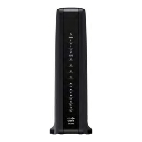
  9. Cisco DPC2325 User manual

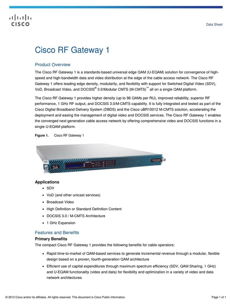
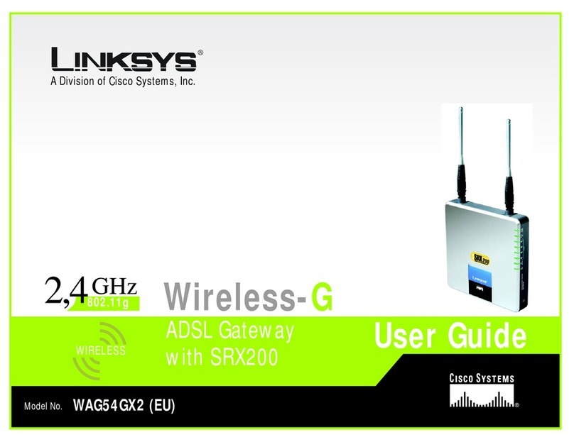
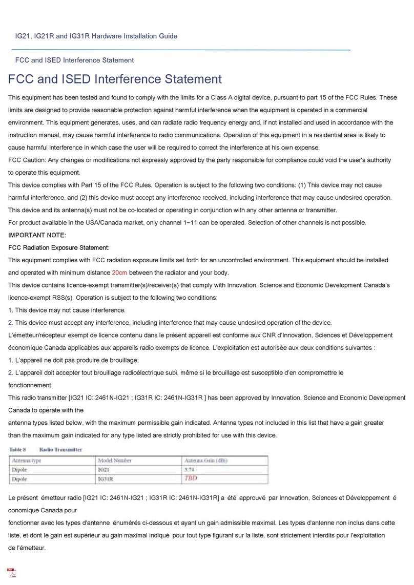
Cisco DPC2325 User manual

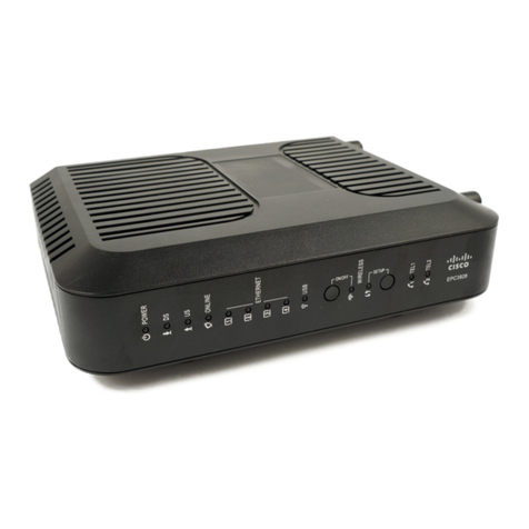
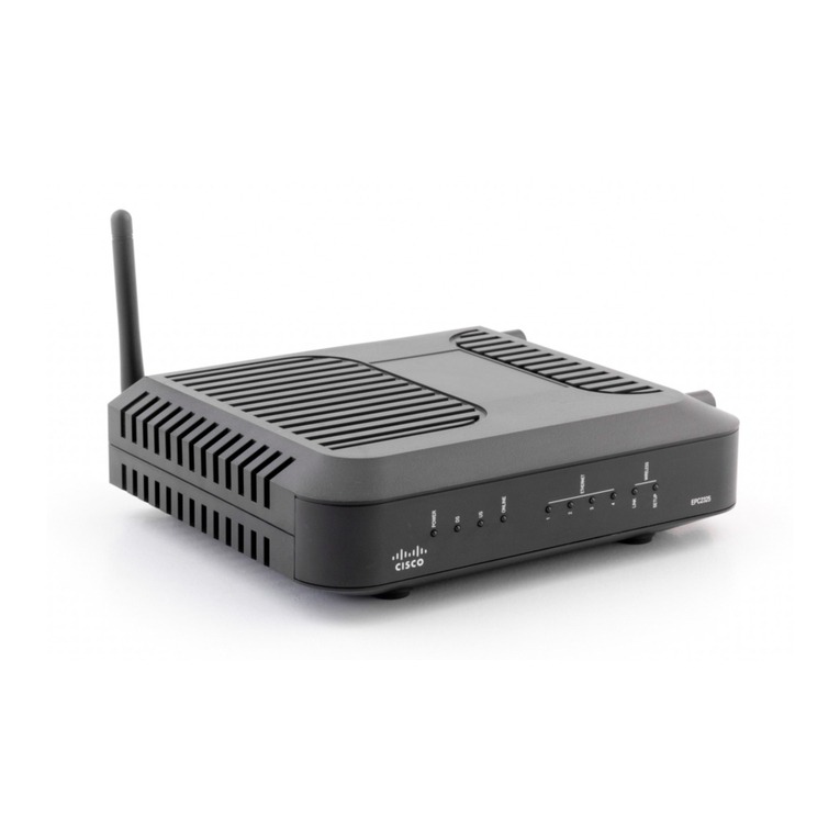
Cisco Model DPC/EPC2325 DOCSIS
Residential Gateway with Wireless
Access Point User Guide for Rogers
Cable, Inc.
2 TBD Rev A
Notice
to
Installers
In This Document

IMPORTANT SAFETY INSTRUCTIONS ...............................................................3

Introduction...............................................................................................................10

What' In the Carton?...............................................................................................12

Front Panel De cription ...........................................................................................13

Back Panel De cription ............................................................................................14

Where I the Be t Location for My DOCSIS Re idential Gateway? ..................15

How Do I Mount the Modem on a Wall? (Optional)...........................................16

What Are the Sy tem Requirement for Internet Service?..................................19

How Do I Sub cribe to High-Speed Internet Service?.........................................20

How Do I Connect My Device to U e the Internet?...........................................21

How Do I Configure My DOCSIS Re idential Gateway?...................................23

How Do I Trouble hoot My Internet Service In tallation?...............................103

Frequently A ked Que tion .................................................................................104

Having Difficulty? ..................................................................................................111

Tip for Improved Performance ...........................................................................112

Front Panel LED Statu Indicator Function .......................................................113

For Information.......................................................................................................116

Notice ......................................................................................................................117

Third Party Software Licen e Notice For Ci co Model DPC/EPC2325
DOCSIS Re idential Gateway with Wirele Acce .........................................118
TBD Rev A 3
IMPORTANT
SAFETY
INSTRUCTIONS
IMPORTANT SAFETY INSTRUCTIONS
Notice to Installers
The ervicing in truction in thi notice are for u e by qualified ervice per onnel only. To reduce the
ri k of electric hock, do not perform any ervicing other than that contained in the operating
in truction , unle you are qualified to do o.
Notice à l’attention es installateurs e réseaux câblés
Le in truction relative aux intervention d’entretien, fournie dan la pré ente notice, ’adre ent
exclu ivement au per onnel technique qualifié. Pour réduire le ri que de choc électrique , n’effectuer
aucune intervention autre que celle décrite dan le mode d'emploi et le in truction relative au
fonctionnement, à moin que vou ne oyez qualifié pour ce faire.
4 TBD Rev A
IMPORTANT
SAFETY
INSTRUCTIONS
Mitteilung für CATV-Techniker
Die in die er Mitteilung aufgeführten Wartung anwei ungen ind au chließlich für qualifizierte
Fachper onal be timmt. Um die Gefahr eine elektri chen Schlag zu reduzieren, ollten Sie keine
Wartung arbeiten durchführen, die nicht au drücklich in der Bedienung anleitung aufgeführt ind,
außer Sie ind zur Durchführung olcher Arbeiten qualifiziert.
Aviso a los instala ores e sistemas CATV
La in truccione de reparación contenida en el pre ente avi o on para u o exclu ivo por parte de
per onal de mantenimiento cualificado. Con el fin de reducir el rie go de de carga eléctrica, no realice
ninguna otra operación de reparación di tinta a la contenida en la in truccione de funcionamiento, a
meno que po ea la cualificación nece aria para hacerlo.
20080814_In taller820_Intl
TBD Rev A 5
IMPORTANT
SAFETY
INSTRUCTIONS
IMPORTANT SAFETY INSTRUCTIONS
1) Read the e in truction .
2) Keep the e in truction .
3) Heed all warning .
4) Follow all in truction .
5) Do not u e thi apparatu near water.
6) Clean only with dry cloth.
7) Do not block any ventilation opening . In tall in accordance with the
manufacturer' in truction .
8) Do not in tall near any heat ource uch a radiator , heat regi ter , tove ,
or other apparatu (including amplifier ) that produce heat.
9) Do not defeat the afety purpo e of the polarized or grounding-type plug. A
polarized plug ha two blade with one wider than the other. A grounding-
type plug ha two blade and a third grounding prong. The wide blade or
the third prong are provided for your afety. If the provided plug doe not
fit into your outlet, con ult an electrician for replacement of the ob olete
outlet.
10) Protect the power cord from being walked on or pinched particularly at
plug , convenience receptacle , and the point where they exit from the
apparatu .
11) Only u e attachment /acce orie pecified by the manufacturer.
12) U e only with the cart, tand, tripod, bracket, or table pecified by the
manufacturer, or old with the apparatu . When a cart i u ed, u e caution
when moving the cart/apparatu combination to avoid injury from tip-over.
13) Unplug thi apparatu during lightning torm or when unu ed for long
period of time.
14) Refer all ervicing to qualified ervice per onnel. Servicing i required when
the apparatu ha been damaged in any way, uch a a power- upply cord
or plug i damaged, liquid ha been pilled or object have fallen into the
apparatu , the apparatu ha been expo ed to rain or moi ture, doe not
operate normally, or ha been dropped.
Power Source Warning
A label on thi product indicate the correct power ource for thi product. Operate thi product only
from an electrical outlet with the voltage and frequency indicated on the product label. If you are
uncertain of the type of power upply to your home or bu ine , con ult your ervice provider or your
local power company.
The AC inlet on the unit mu t remain acce ible and operable at all time .
6 TBD Rev A
IMPORTANT
SAFETY
INSTRUCTIONS
Groun the Pro uct
WARNING: Avoid electric shock and fire hazard! If this product connects to coaxial
cable wiring be sure the cable system is grounded (earthed). Grounding provides some
protection against voltage surges and built-up static charges.
Protect the Pro uct from Lightning
In addition to di connecting the AC power from the wall outlet, di connect the ignal input .
Verify the Power Source from the On/Off Power Light
When the on/off power light i not illuminated, the apparatu may till be connected to the power
ource. The light may go out when the apparatu i turned off, regardle of whether it i till plugged
into an AC power ource.
Eliminate AC Mains Overloa s
WARNING: Avoid electric shock and fire hazard! Do not overload AC mains outlets
extension cords or integral convenience receptacles. For products that require battery
power or other power sources to operate them refer to the operating instructions for
those products.
Provi e Ventilation an Select a Location

Remove all packaging material before applying power to the product.

Do not place thi apparatu on a bed, ofa, rug, or imilar urface.

Do not place thi apparatu on an un table urface.

Do not in tall thi apparatu in an enclo ure, uch a a bookca e or rack, unle the in tallation
provide proper ventilation.

Do not place entertainment device ( uch a VCR or DVD ), lamp , book , va e with liquid , or
other object on top of thi product.

Do not block ventilation opening .
Protect from Exposure to Moisture an Foreign Objects
WARNING: Avoid electric shock and fire hazard! Do not expose this product to
liquids rain or moisture. Do not expose this product to dripping or splashing liquids
rain or moisture. Objects filled with liquids such as vases should not be placed on
this apparatus.
WARNING: Avoid electric shock and fire hazard! Unplug this product before cleaning.
Do not use a liquid cleaner or an aerosol cleaner. Do not use a magnetic/static cleaning
device (dust remover) to clean this product.
WARNING: Avoid electric shock and fire hazard! Never push objects through the
openings in this product. Foreign objects can cause electrical shorts that can result in
electric shock or fire.
TBD Rev A 7
IMPORTANT
SAFETY
INSTRUCTIONS
Service Warnings
WARNING: Avoid electric shock! Do not open the cover of this product. Opening or
removing the cover may expose you to dangerous voltages. If you open the cover your
warranty will be void. This product contains no user-serviceable parts.
Check Pro uct Safety
Upon completion of any ervice or repair to thi product, the ervice technician mu t perform afety
check to determine that thi product i in proper operating condition.
Protect the Pro uct When Moving It
Alway di connect the power ource when moving the apparatu or connecting or di connecting
cable .
20081112_Modem DSL_Safety
8 TBD Rev A
FCC
Compliance
FCC Compliance
Unite States FCC Compliance
Thi device ha been te ted and found to comply with the limit for a Cla B digital device,
pur uant to part 15 of the FCC Rule . The e limit are de igned to provide rea onable
protection again t uch interference in a re idential in tallation. Thi equipment generate ,
u e , and can radiate radio frequency energy. If not in talled and u ed in accordance with the
in truction , it may cau e harmful interference to radio communication . However, there i
no guarantee that interference will not occur in a particular in tallation. If thi equipment
doe cau e harmful interference to radio or televi ion reception, which can be determined by
turning the equipment OFF and ON, the u er i encouraged to try to correct the interference
by one or more of the following mea ure :

Reorient or relocate the receiving antenna.

Increa e the eparation between the equipment and receiver.

Connect the equipment into an outlet on a circuit different from that to which the
receiver i connected.

Con ult the ervice provider or an experienced radio/televi ion technician for help.
Any change or modification not expre ly approved by Ci co Sy tem , Inc., could void the
u er' authority to operate the equipment.
The information hown in the FCC Declaration of Conformity paragraph below i a
requirement of the FCC and i intended to upply you with information regarding the FCC
approval of thi device. The phone numbers listed are for FCC-related questions only and not
intended for questions regarding the connection or operation for this device. Please contact your
service provider for any questions you may have regarding the operation or installation of this device.
Declaration of Conformity
Thi device complie with Part 15 of FCC
Rule . Operation i ubject to the following two
condition : 1) the device may not cau e
harmful interference, and 2) the device mu t
accept any interference received, including
interference that may cau e unde ired
operation.
DOCSIS Re idential Gateway
Model: DPC/EPC2325
Manufactured by:
Ci co Sy tem , Inc.
5030 Sugarloaf Parkway
Lawrenceville, Georgia 30044 USA
Telephone: 770-236-1077
Cana a EMI Regulation
Thi Cla B digital apparatu complie with Canadian ICES-003.
Cet appareil numérique de la cla B e t conforme à la norme NMB-003 du Canada.
TBD Rev A 9
FCC
Compliance
Ra iation Exposure Statements
Note: Thi tran mitter mu t not be co-located or operated in conjunction with any other
antenna or tran mitter. Thi equipment hould be in talled and operated with a minimum
di tance of 7.9 inche (20 cm) between the radiator and your body.
US
Thi y tem ha been evaluated for RF expo ure for human in reference to ANSI C 95.1
(American National Standard In titute) limit . The evaluation wa ba ed on evaluation per
ANI C 95.1 and FCC OET Bulletin 65C rev 01.01. The minimum eparation di tance from the
antenna to general by tander i 7.9 inche (20 cm) to maintain compliance.
Cana a
Thi y tem ha been evaluated for RF expo ure for human in reference to ANSI C 95.1
limit . The evaluation wa ba ed on evaluation per RSS-102 Rev 2. The minimum eparation
di tance from the antenna to general by tander i 7.9 inche (20 cm) to maintain compliance.
EU
Thi y tem ha been evaluated for RF expo ure for human in reference to the ICNIRP
(International Commi ion on Non-Ionizing Radiation Protection) limit . The evaluation wa
ba ed on the EN 50385 Product Standard to Demon trate Compliance of Radio Ba e Station
and Fixed Terminal for Wirele Telecommunication Sy tem with ba ic re triction or
reference level related to Human Expo ure to Radio Frequency Electromagnetic Field from
300 MHz to 40 GHz. The minimum eparation di tance from the antenna to general
by tander i 20 cm (7.9 inche ).
Australia
Thi y tem ha been evaluated for RF expo ure for human a referenced in the Au tralian
Radiation Protection tandard and ha been evaluated to the ICNIRP (International
Commi ion on Non-Ionizing Radiation Protection) limit . The minimum eparation di tance
from the antenna to general by tander i 20 cm (7.9 inche ).
20081016 FCC DSL_Dom and Intl
10 TBD Rev A
Intro uction
Intro uction
Intro uction
Welcome to the exciting world of high- peed Internet! Your new Ci co® Model
DPC/EPC2325 DOCSIS® Re idential Gateway i a cable modem that meet indu try
tandard for high- peed data connectivity. The DPC/EPC2325 re idential gateway
deliver data via wired (Ethernet) or wirele gateway capabilitie to connect a
variety of device in the home or mall office and upport high- peed data acce all
in one device. With a DPC/EPC2325 re idential gateway, your Internet enjoyment,
home and bu ine communication , and per onal productivity will urely oar.
Thi guide provide procedure and recommendation for placing, in talling,
configuring, operating, and trouble hooting your DPC/EPC2325 re idential gateway
for high- peed Internet ervice for your home or office. Refer to the appropriate
ection in thi guide for the pecific information you need for your ituation. Contact
your ervice provider for more information about ub cribing to Internet ervice .
Benefits an Features
Your new DPC/EPC2325 re idential gateway offer the following out tanding
benefit and feature :
Compliant with DOCSIS/EuroDOCSIS™ 2.0, 1.1, and 1.0 tandard along with
PacketCable™/EuroPacketCable™ pecification to deliver high-end
performance and reliability
High performance broadband Internet connectivity to energize your online
experience
Four 10/100BASE-T Ethernet port to provide wired connectivity
802.11g Wirele Acce Point with 4 ervice et identifier (SSID )
Wi-Fi Protected Setup (WPS), including a pu h button witch to activate WPS for
implified and ecure wirele etup
U er configurable Parental Control block acce to unde irable Internet ite
Advanced firewall technology deter hacker and protect the home network
from unauthorized acce
Attractive compact de ign that allow for vertical, horizontal, or wall-mounted
operation
TR-068 compliant color-coded interface port and corre ponding cable implify
in tallation and etup
TBD Rev A 11
Intro uction
DOCSIS-5 compliant LED labeling and behavior provide a u er and technician
friendly method to check operational tatu and act a a trouble hooting tool
Allow automatic oftware upgrade by your ervice provider
12 TBD Rev A
What's
In
the
Carton?
What's In the Carton?
When you receive your wirele home gateway, you hould check the equipment
and acce orie to verify that each item i in the carton and that each item i
undamaged. The carton contain the following item :
One of the DPC/EPC2325 DOCSIS
Re idential Gateway ver ion
One power adapter (model
requiring external power upply)
One Ethernet cable (CAT5/RJ-45)
One CD-ROM containing the u er
guide
If any of the e item are mi ing or damaged, plea e contact your ervice provider
for a i tance.
Note: You will need an optional cable ignal plitter and additional tandard RF
coaxial cable if you want to connect a VCR, a Digital Home Communication
Terminal (DHCT) or a et-top converter, or a TV to the ame cable connection a
your wirele home gateway.
TBD Rev A 13
Front
Panel
Description
Front Panel Description
The front panel of your re idential gateway provide LED tatu indicator that
indicate how well and at what tate your re idential gateway i operating. See Front
Panel LED Status Indicator Functions (on page 113), for more information on front
panel LED tatu indicator function .
Model DPC2325
1
POWER—ON, power i applied to the wirele re idential gateway
2
DS—ON, the wirele re idential gateway i receiving data from the cable
network
3
US—ON, the wirele re idential gateway i ending data to the cable network
4
ONLINE—ON, the wirele re idential gateway i regi tered on the network and
fully operational
5
ETHERNET 1 - 4—ON, a device i connected to one of the Ethernet port .
BLINKING indicate that data i being tran ferred over the Ethernet connection
6
WIRELESS LINK—ON, the Wirele Acce Point i operational. BLINKING
indicate that data i being tran ferred over the wirele connection. OFF indicate
that the wirele acce point ha been di abled by the u er
7
WIRELESS SETUP—OFF (normal condition) wirele etup i not active.
BLINKING indicate the u er ha activated wirele etup to add new wirele
client on the wirele network
14 TBD Rev A
Back
Panel
Description
Back Panel Description
The following illu tration how the de cription and function of the back panel
component on the DPC/EPC2325.
External Power Supply Mo el
Model DPC/EPC2325
1
POWER—Connect the re idential gateway to the power adapter that i provided with
your re idential gateway
CAUTION:
Avoid damage to your equipment. Only use the power supply
that is provided with your residential gateway.
2
WIRELESS SETUP—Pre ing thi witch initiate wirele etup, thi feature allow the
u er to add new Wi-Fi Protected Setup (WPS) compliant wirele client to the home
network
3
ETHERNET—Four RJ-45 Ethernet port connect to the Ethernet port on your PC or your
home network
4
REBOOT—A momentary pre ing (1-2 econd ) of thi witch reboot the re idential
gateway. Pre ing the witch for more than ten econd cau e a re et-to-factory-default
of all etting and then reboot the gateway
CAUTION:
The Reboot button is for maintenance purposes only. Do not use
unless instructed to do so by your service provider. Doing so
may cause you to lose any cable modem settings you have
selected.
5
CABLE—F-connector connect to an active cable ignal from your ervice provider
6
ANTENNA—Connection for external 802.11 antenna
TBD Rev A 15
Where
Is
the
Best
Location
for
My
DOCSIS
Resi ential
Gateway?
Where Is the Best Location for My DOCSIS Resi ential
Gateway?
The ideal location for your re idential gateway i where it ha acce to outlet and
other device . Think about the layout of your home or office, and con ult with your
ervice provider to elect the be t location for your re idential gateway. Read thi
u er guide thoroughly before you decide where to place your re idential gateway.
Con ider the e recommendation :
Po ition your PC and re idential gateway o that they are located near an AC
power outlet.
Po ition your PC and re idential gateway o that they are located near an
exi ting cable input connection to eliminate the need for an additional cable
outlet. There hould be plenty of room to guide the cable away from the modem
and the PC without training or crimping them.
Airflow around the re idential gateway hould not be re tricted.
Choo e a location that protect the re idential gateway from accidental
di turbance or harm.
16 TBD Rev A
How
Do
I
Mount
the
Mo em
on
a
Wall?
(Optional)
How Do I Mount the Mo em on a Wall? (Optional)
You can mount the re idential gateway on a wall u ing two wall anchor , two
crew , and the mounting lot located on the unit. The modem can be mounted
vertically or horizontally.
Before You Begin
Before you begin, choo e an appropriate mounting place. The wall can be made of
cement, wood, or drywall. The mounting location hould be free of ob truction on
all ide , and the cable hould be able to ea ily reach the re idential gateway
without train. Leave ufficient clearance between the bottom of the re idential
gateway and any flooring or helving underneath to allow acce to cabling. In
addition, leave enough lack in all cable o that the re idential gateway can be
removed for any required maintenance without di connecting the cable . Al o,
verify that you have the following item :
Two wall anchor for #8 x 1-inch crew
Two #8 x 1-inch pan head heet metal crew
Drill with a 3/16-in. wood or ma onry bit, a appropriate for the wall
compo ition
A copy of the wall-mounting illu tration hown on the following page
TBD Rev A 17
How
Do
I
Moun
t
the
Mo em
on
a
Wall?
(Optional)
Mount the modem a hown in one of the following illu tration .
18 TBD Rev A
How
Do
I
Mount
the
Mo em
on
a
Wall?
(Optional)
Location an Dimensions of the Wall-Mounting Slots
The following illu tration how the location and dimen ion of the wall-mounting
lot on the bottom of the modem. U e the information on thi page a a guide for
mounting your modem to the wall.
Mounting the Resi ential Gateway on a Wall
1U ing a drill with a 3/16-inch bit, drill two hole at the ame height and 4 inche
apart.
Note: The preceding graphic illu trate the location of the mounting hole on the
back of the re idential gateway.
2Are you mounting the re idential gateway into a drywall or concrete urface
where a wooden tud i available?
If yes, go to tep 3.
If no, drive the anchor bolt into the wall, and in tall the mounting crew
into the anchor bolt ; leave a gap of about 1/4-inch between the crew head
and the wall. Then, go to tep 4.
3In tall the mounting crew into the wall; leave a gap of about 1/4-inch between
the crew head and the wall. Then, go to tep 4.
4Verify that no cable or wire are connected to the re idential gateway.
5Lift the re idential gateway into po ition. Slip the large end of both mounting
lot (located in the back of the re idential gateway) over the mounting crew ,
and then lide the re idential gateway down until the narrow end of the keyhole
lot contact the crew haft.
Important: Verify that the mounting crew ecurely upport the re idential
gateway before you relea e the unit.
TBD Rev A 19
What
Are
the
System
Requirements
for
Internet
Service?
What Are the System Requirements for Internet Service?
To en ure that your re idential gateway operate efficiently for high- peed Internet
ervice, verify that all of the Internet device on your y tem meet or exceed the
following minimum hardware and oftware requirement .
Note: You will al o need an active cable input line and an Internet connection.
Minimum System Requirements for a PC
A PC with a Pentium MMX 133 proce or or greater
32 MB of RAM
Web brow ing oftware
CD-ROM drive
Minimum System Requirements for Macintosh
MAC OS 7.5 or later
32 MB of RAM
System Requirements for an Ethernet Connection
A PC with Micro oft Window 2000 operating y tem (or later) with TCP/IP
protocol in talled, or an Apple Macinto h computer with TCP/IP protocol
in talled
An active 10/100BASE-T Ethernet network interface card (NIC) in talled
20 TBD Rev A
How
Do
I
Subscribe
to
High
-
Spee
Internet
Service?
How Do I Subscribe to High-Spee Internet Service?
Before you can u e your re idential gateway, you need to have a high- peed Internet
acce account. If you do not have a high- peed Internet acce account, you need to
et up an account with your local ervice provider. Choo e one of the two option in
thi ection.
I Do Not Have a High-Spee Internet Access Account
If you do not have a high- peed Internet acce account, your ervice provider will
et up your account and become your Internet Service Provider (ISP). Internet acce
enable you to end and receive e-mail, acce the World Wide Web, and receive
other Internet ervice .
You will need to give your ervice provider the following information:
The erial number of the modem
The Media Acce Control (MAC) addre of the modem
The e number appear on a bar code label located on the re idential gateway. The
erial number con i t of a erie of alphanumeric character preceded by S/N. The
MAC addre con i t of a erie of alphanumeric character preceded by CM MAC.
The following illu tration how a ample bar code label.
Write down the e number in the pace provided here.
Serial Number _______________________
MAC Addre ________________________
I Alrea y Have an Existing High-Spee Internet Access Account
If you have an exi ting high- peed Internet acce account, you mu t give your
ervice provider the erial number and the MAC addre of the re idential gateway.
Refer to the erial number and MAC addre information li ted previou ly in thi
ection.
Note: You may not be able to continue to u e your exi ting e-mail account with your
re idential gateway. Contact your ervice provider for more information.

Other manuals for DPC2325

1

This manual suits for next models

1

Other Cisco Gateway manuals

Cisco DPC3929CM User manual

Cisco

Cisco DPC3929CM User manual

Cisco AudioCodes MP-1288 User manual

Cisco

Cisco AudioCodes MP-1288 User manual

Cisco DPC3848 User manual

Cisco

Cisco DPC3848 User manual

Cisco RF 1 User manual

Cisco

Cisco RF 1 User manual

Cisco VG204 User manual

Cisco

Cisco VG204 User manual

Cisco DPA 7610 Instruction Manual

Cisco

Cisco DPA 7610 Instruction Manual

Cisco DPC2434 User manual

Cisco

Cisco DPC2434 User manual

Cisco 3527 PRI G Installation and operation manual

Cisco

Cisco 3527 PRI G Installation and operation manual

Cisco 450 Manual

Cisco

Cisco 450 Manual

Cisco Linksys AG310 User manual

Cisco

Cisco Linksys AG310 User manual

Cisco IC3000 Manual

Cisco

Cisco IC3000 Manual

Cisco ENH900EXT User manual

Cisco

Cisco ENH900EXT User manual

Cisco AS5400XM Original instructions

Cisco

Cisco AS5400XM Original instructions

Cisco SIEMENS HICOM 330E Installation and operating instructions

Cisco

Cisco SIEMENS HICOM 330E Installation and operating instructions

Cisco ISDN GW 3241 User manual

Cisco

Cisco ISDN GW 3241 User manual

Cisco DPC2425 User manual

Cisco

Cisco DPC2425 User manual

Cisco Expressway CE1000 Appliance User manual

Cisco

Cisco Expressway CE1000 Appliance User manual

Cisco VGD-1T3 User manual

Cisco

Cisco VGD-1T3 User manual

Cisco LINKSYS RFC 2364 Original operating instructions

Cisco

Cisco LINKSYS RFC 2364 Original operating instructions

Cisco 1100 Series Manual

Cisco

Cisco 1100 Series Manual

Cisco Linksys WAG310G User manual

Cisco

Cisco Linksys WAG310G User manual
Cisco DPC3825 User manual

Cisco

Cisco DPC3825 User manual

Cisco DPC2434 Operating instructions

Cisco

Cisco DPC2434 Operating instructions

Cisco VG248 - Gateway User manual

Cisco

Cisco VG248 - Gateway User manual

Popular Gateway manuals by other brands

eTactica EG-200 installation manual

eTactica

eTactica EG-200 installation manual

Weinzierl KNX 886 Operation and installation manual

Weinzierl

Weinzierl KNX 886 Operation and installation manual

CloudGate Marwis user manual

CloudGate

CloudGate Marwis user manual

Motorola SURFBOARD SBG1000 White paper

Motorola

Motorola SURFBOARD SBG1000 White paper

D-Link DVG?6001G quick guide

D-Link

D-Link DVG?6001G quick guide

Teltonika TRB140 quick start guide

Teltonika

Teltonika TRB140 quick start guide

ZyXEL Communications P-27xx Series user guide

ZyXEL Communications

ZyXEL Communications P-27xx Series user guide

Vanderbilt SPCG310 quick start guide

Vanderbilt

Vanderbilt SPCG310 quick start guide

Allo.com E1 user manual

Allo.com

Allo.com E1 user manual

Epygi QUADRO FXO Specifications

Epygi

Epygi QUADRO FXO Specifications

Johnson Controls WNC1800 user guide

Johnson Controls

Johnson Controls WNC1800 user guide

Maretron IPG100 Firmware recovery procedure

Maretron

Maretron IPG100 Firmware recovery procedure

ICP DAS USA PFN-2000 Series HOW TO UPDATE FIRMWARE

ICP DAS USA

ICP DAS USA PFN-2000 Series HOW TO UPDATE FIRMWARE

AudioCodes Media Pack MP-11x Configuration guide

AudioCodes

AudioCodes Media Pack MP-11x Configuration guide

Yes Zoom quick start guide

Yes

Yes Zoom quick start guide

TECOM AG-300 Plus2 Operation manual

TECOM

TECOM AG-300 Plus2 Operation manual

WeBeHome Home Gateway 2 Plus quick start guide

WeBeHome

WeBeHome Home Gateway 2 Plus quick start guide

Watts TekmarNet 4 Installation, operation and maintenance manual

Watts

Watts TekmarNet 4 Installation, operation and maintenance manual

manuals.online logo
manuals.online logoBrands
  • About & Mission
  • Contact us
  • Privacy Policy
  • Terms and Conditions

Copyright 2025 Manuals.Online. All Rights Reserved.