Cisco TelePresence VX Clinical Assistant User manual

141299.21 Cisco TelePresence VX Clinical AssistantTM CTS-CA2-K9/CTS-CA2-P240V-K9 v1.2 | 2013 JAN | © 2012-2013 Cisco Systems, Inc. All rights reserved. 1
Cisco TelePresence VX Clinical AssistantTM
INSTALLATION AND USER GUIDE

141299.21 Cisco TelePresence VX Clinical AssistantTM CTS-CA2-K9/CTS-CA2-P240V-K9 v1.2 | 2013 JAN | © 2012-2013 Cisco Systems, Inc. All rights reserved. 2
Table of Contents
Contraindications.................................................................3
Introduction .........................................................................4
Safety Precautions ..............................................................5
Warning ...........................................................................5
Environmental Issues .......................................................5
Waste Handling ...............................................................5
Important Safeguards..........................................................6
Using System in a Medical Environment..........................6
Wireless Access Point Compliance .................................6
ElectroStatic Discharge (ESD) .........................................6
Battery Maintenance........................................................6
Operator Safety Summary...................................................7
Equipment Markings ........................................................7
Warnings .............................................................................8
Not Intended For Dialing Emergency Medical Services ..8
Improper Transport Methods ..........................................8
Loss of Connectivity .......................................................8
Proper Training Is Required ........................................8
Camera May Not Focus ..................................................8
Audio Distortions ............................................................8
PAL-N Video Signal Not Available....................................8
System Assembly................................................................9
Tools Required for Assembly ...........................................9
Installing the Cisco PrecisionHD Camera...........................10
Installing the Rechargeable Battery ...................................11
Installing Options ...............................................................12
Drawer Module, PC Cabinet Module, PC Shelf, and
Storage Pods.................................................................12
Laptop Shelf ..................................................................13
Scope Hooks.................................................................14
Wireless Access Point Mount ........................................14
Splash Cover .................................................................14
Retractable AC Cord Caddy ..........................................15
Retractable Network Cord Caddy..................................15
PC Cabinet with Switch .................................................16
Installing Optional Wireless Access Point (WAP) ...........17
Installing Optional Network Switch.................................17
Installing Optional WAP and Switch ...............................18
Enabling the Dual Display Option ...................................19
Power Schematics ............................................................20
Audio Schematics .............................................................21
Video Schematics .............................................................22
Control Schematics...........................................................23
Using the System..............................................................24
Turning the System On ..................................................24
Call Controls......................................................................25
Source Control and Rear Interface....................................26
Headphone and Audio Input..............................................27
Headphone Output ........................................................27
Audio Input ....................................................................27
Cleaning the System .........................................................28
Troubleshooting.................................................................29
Frequently Asked Questions..............................................30
Technical Specifications ....................................................31
Electromagnetic Emissions and Immunity Summary..........32
What’s in this guide?
For more information about configuring and using your
Cisco product, refer to the following URL:
http://www.cisco.com/go/telepresence/docs

141299.21 Cisco TelePresence VX Clinical AssistantTM CTS-CA2-K9/CTS-CA2-P240V-K9 v1.2 | 2013 JAN | © 2012-2013 Cisco Systems, Inc. All rights reserved. 3
Indications for Use
The Cisco TelePresence VX Clinical AssistantTM (VX
Clinical Assistant) enables secure and effective audio/
video communication between multiple healthcare
providers and between providers and patients.
The system transmits real-time audio and video
captured by a high-definition camera and integrated
microphone. It also receives real-time audio and
video from a corresponding functionally like system
in a remote location. Finally, the VX Clinical Assistant
supports transmission of real-time audio and video
from peripheral audio/visual medical devices, which
may be connected to standard audio and video inputs
provided on the system.
The VX Clinical Assistant is intended to facilitate remote
provider/patient and provider/provider consultations.
These consultations should always be conducted with
a licensed medical professional physically in the room
with the patient.
Contraindications
The VX Clinical Assistant is not intended to substitute
for the in-person physical examination of a patient or
as a substitute for direct medical intervention. It is also
not intended for real-time, active, or online patient
monitoring, nor is it intended to provide time sensitive
data or alarms. The VX Clinical Assistant does not
support transmission of numerical telemetric/serial
data and is not intended for use with non-audio/visual
medical devices.
33 in
(83.82 cm)
35 in
(88.9 cm)
71 in
(180.34 cm)
280 lbs / 127 kg
Diameter: 27 in. (68.5 cm)
Height: 67 in. (170 cm)
Weight: 170 lb (76.2 kg) (without accessory options)

141299.21 Cisco TelePresence VX Clinical AssistantTM CTS-CA2-K9/CTS-CA2-P240V-K9 v1.2 | 2013 JAN | © 2012-2013 Cisco Systems, Inc. All rights reserved. 4
Introduction
The VX Clinical Assistant brings the power of
telepresence to healthcare environments. Designed for
mobility and ease of use at the point of care, the VX
Clinical Assistant is a high-definition video collaboration
system with functionality that facilitates medical use
cases ranging from remote patient consultations
to virtual care teams and medical education. This
mobile telemedicine endpoint is part of the Cisco
TelePresence portfolio, which offers a total solution
approach including content sharing, recording, firewall
traversal, and management capabilities. With the VX
Clinical Assistant healthcare providers can overcome
the barrier of distance and work more productively
through remote face-to-face collaboration in a medical
setting.
Key Features of VX Clinical Assistant:
•Lightweight and highly mobile with integrated industrial
design to maximize durability and functionality in a
medical environment
•Cisco TelePresence SX Series codec featuring 1080p30
video, full-duplex audio, and high-definition (HD) content
sharing
•1080p HD camera with full pan-tilt-zoom (PTZ) capability
- 4x zoom standard, 12x zoom optional
•24-inch 1080p HD LED backlit display
•Tactile control panel offering simple system control with
minimal training, plus infrared remote control for full
untethered system operation
•Both AC and rechargeable battery power through
medical-grade isolation transformer
•Flexible range of storage module options for computers,
medical devices, supplies, etc.
•Five 5-inch hospital-grade, antistatic free running
castors with foot locks
24” Display
PrecisionHD Camera
Integrated
Microphone
Integrated
Speakers
Source
Control
Camera Shelf
Handle
Audio Input
(3.5mm)
Headphone
Audio Output
(1/4”)
Potential
Equalization
Terminal
Ethernet
Handles (4x)
Power
Outlet (2x)
5” Locking Wheels
(5x)
Power Control
and Battery
Meter Panel
Internal Rechargeable Battery
and Isolation Transformer
AC Power Inlet
Cable
Management
Rear
Interface
Height-adjustable
Locking Drawer
(OPTION)
Height-adjustable
Shelf (OPTION)
Retractable Network
Cable (OPTION)
Fuse (2A)
Height-adjustable
Storage Bin
(OPTION)
Retractable Power
Cable (OPTION)
Wireless Access
Point (OPTION)
Codec Remote
and Holder
Splash Cover
(OPTION)
Work Surface
Height-
adjustable
Locking PC
Cabinet
(OPTION)
Laptop Tray
(OPTION)
Scope Hooks
(OPTION)

141299.21 Cisco TelePresence VX Clinical AssistantTM CTS-CA2-K9/CTS-CA2-P240V-K9 v1.2 | 2013 JAN | © 2012-2013 Cisco Systems, Inc. All rights reserved. 5
Safety Precautions
Warning
Precaution should be taken during transportation of
the system. It is recommended that the operator use
caution when wheeling the unit over doorstops and/
or into elevators to ensure their safety and prevent
damage to the unit.
For Customers In North America
This equipment complies to the limits for a Class A
digital device, pursuant to Part 15 of the FCC Rules.
These limits are designed to provide reasonable
protection against harmful interference when the
equipment is operated in a commercial environment.
This equipment generates, uses, and can radiate
radio frequency energy, which may cause harmful
interference to radio communications.
You are cautioned that any changes or modifications
not expressly approved in this manual could void your
authority to operate this equipment
Environmental Issues
Thank you for buying a product, which contributes
to a reduction in pollution, and thereby helps save
the environment. Our products reduce the need for
travel and transport and thereby reduce pollution. Our
products have either none or few consumable parts
(chemicals, toner, gas, paper). Our products are low
energy consuming products.
Battery handling
Batteries for the Remote Control are Long Life Alkaline
batteries; please follow guidelines on the packing
material for handling and disposal of the batteries.
The system enclosed battery (rechargeable battery for
wireless use) in this product is non-user replaceable
and should be removed by a service technician only.
CAUTION
RISK OF EXPLOSION IF BATTERY IS REPLACED BY
AN INCORRECT TYPE. DISPOSE OF USED BATTERIES
ACCORDING TO MANUFACTURER INSTRUCTIONS.
Production of Products
Our factories employ efficient environmental methods
for reducing waste and pollution and ensuring the
products are recyclable.
Waste Handling
EU Battery and WEEE Directives
Your Cisco product may contain a user replaceable
battery or a permanently affixed battery as indicated in
the user manual. For product safety and data integrity
reasons a permanently affixed battery should only
be removed or replaced professionally by a repair
technician or waste management professional. Please
contact Cisco or an authorized service agent if the
product fails to perform due to malfunction of the
permanently affixed battery.
This symbol on a Cisco product, battery
or packaging means that the product and/
or battery should not be disposed of with
your household waste.
It is your responsibility to dispose of your waste
equipment and batteries separately from your
household waste and in accordance with local laws and
regulations. The correct disposal of your old equipment
and batteries will help prevent potential negative
consequences for the environment and human health.
Please use the nearest waste collection facility as
directed by your municipality or your retailer.

141299.21 Cisco TelePresence VX Clinical AssistantTM CTS-CA2-K9/CTS-CA2-P240V-K9 v1.2 | 2013 JAN | © 2012-2013 Cisco Systems, Inc. All rights reserved. 6
Important Safeguards
Using System in a Medical Environment
No currently available technology can completely
substitute for the in-person physical examination of an
individual patient. Cisco Telepresence products have
the ability to provide high quality audio/high resolution
video over long distances; and when used properly,
these products can provide tools for physicians and
other medical professionals who are unable to examine
a patient in person. The use and value of the system
will vary depending on the specific circumstances of
the patient’s condition, transmission speed and the
ability of audio/visual technology to be used for remote
evaluations. Ultimately, judgments on how this tool
should be used must be at the individual discretion of
the physician or other medical personnel supervising
the patient’s care.
All the equipment connected to this system shall be
certified according to UL Standard UL60601-1 or other
IEC/ISO/CSA Standards applicable to the equipment.
When this system is used
together with other
equipment in the patient
area*, the equipment shall
be either powered by an
isolation transformer or
connected to the power
outlet that is at the rear of
the cart, unless it is
certified according to UL Standard UL60601-1.
NOTE: The power outlet provided in the system is
powered from an isolation transformer. The maximum
output rating of this outlet is 150 Watts.
CAUTION:
The leakage current could increase when connected to
other equipment.
The operator should take precautions to avoid touching
the rear panel input and output circuitry and the patient
at the same time.
To isolate the system from the mains supply remove
the mains plug from the wall socket.
Warning on Power Connection
Use only with the supplied power cords or cords that
meet local hospital-grade requirements. Users in the
United States and Canada should use hospital-grade
cords that meet the following requirements:
United States Canada
Plug Type Hospital Grade Hospital Grade
Cord Type SJT3 x 18 AWG SJT3 x 18 AWG
Minimum Cord
Det Rating 10A/125V 10A/125V
Saftey Approval CSA NRTLus CSA
NEVER USE AN EXTENSION CABLE TO POWER THE
SYSTEM.
Wireless Access Point Compliance
Any customer-supplied Wireless Access Point used
with the VX Clinical Assistant must comply with
appropriate regulations in the country of use.
ElectroStatic Discharge (ESD)
When subjected to an electrostatic discharge the
12x system camera image may suffer momentary
interruption - this will self-recover in a few seconds
after the discharge.
To avoid excess electrostatic discharge, floors
should be wood, concrete or ceramic tile. If floors are
covered with synthetic material, the relative humidity
should be at least 30%
Battery Maintenance
To insure maximum longevity of the battery, the VX
Clinical Assistant should periodically be operated on
battery power until the “Low Battery ” warning comes
on. Once the warning sounds the system should be
reconnected to an AC power source until the battery is
fully charged.
[ PATIENT AREA ]

141299.21 Cisco TelePresence VX Clinical AssistantTM CTS-CA2-K9/CTS-CA2-P240V-K9 v1.2 | 2013 JAN | © 2012-2013 Cisco Systems, Inc. All rights reserved. 7
Operator Safety Summary
For your protection, please read these safety
instructions completely before operating the equipment
and keep this manual for future reference. The
information in this summary is intended for persons
who operate the equipment as well as repair (servicing)
personnel. Carefully adhere all warnings, precautions
and instructions on the apparatus, or the ones
described in the operating instructions.
Also, adhere to safety guidelines found in manuals
for any peripheral equipment. For your protection, the
instruction manual for the LCD display is provided.
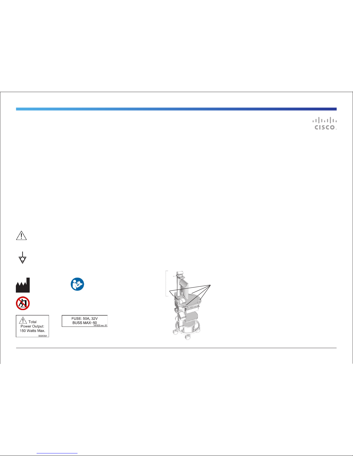
Equipment Markings
The “exclamation mark” within an equilateral triangle
is intended to alert the user to the presence of
important operating and maintenance (servicing)
instructions within literature accompanying the equipment.
The potential equalization terminal is connected to the
system chassis. It can be connected to corresponding
terminals on other equipment to eliminate potential
differences. This terminal is not intended for a protective earth
(grounding) connection near this symbol
Manufacturer
Do not push or pull the unit by the support column.
Use the handles found around the work surface.
• Water and moisture - Do not operate the equipment under
or near water - for example near a bathtub, kitchen sink, or
laundry tub, in a wet basement, or near a swimming pool
or in areas with high humidity.
• Cleaning - Unplug the apparatus from the wall outlet
before cleaning or polishing. Please adhere to the general
cleaning guidelines found in this document’s section:
“Cleaning the System.”
• Grounding- This equipment must be grounded. Never
defeat the ground conductor or operate the equipment
in the absence of a suitably installed ground conductor.
Contact the appropriate electrical inspection authority or
an electrician if you are uncertain that suitable grounding is
available.
• Power-Cord Protection - Route the power cord so as
to avoid it being walked on or pinched by items placed
upon or against it, paying particular attention to the plugs,
receptacles, and the point where the cord exits from the
apparatus.
• Mobility – Before moving the system unplug the power cord
and securely wrap them around the cable wrap brackets.
Unplug connected microphone(s) and carry separately. To
move the cart, use one or more of the cart handles. You
may use the camera tilt handle for local repositioning of the
camera only.
• Ventilation - Do not block any of the ventilation openings
of the apparatus. Install in accordance with the installation
instructions. Never cover the slots and openings with a
cloth or other material. Never install the apparatus near
heat sources such as radiators, heat registers, stoves, or
other apparatus (including amplifiers) that produce heat.
• Attachments - Only use attachments as recommended by
the manufacturer.
• Accessories - Use only with a cart, stand, tripod, bracket,
or table specified by the manufacturer, or sold with the
apparatus. When a cart is used, use caution when moving
the cart/apparatus combination to avoid injury from tip-
over.
• Lightning - Unplug this apparatus during lightning storms
or when unused for long periods of time.
• Servicing - Do not attempt to service the apparatus
yourself as opening or removing covers may expose you
to dangerous voltages or other hazards, and will void the
warranty. Refer all servicing to qualified service personnel.
• Storage - If you need to store the system, ensure that it is
stored in a controlled environment to avoid damage. Refer
to the codec documentation for further guidelines.
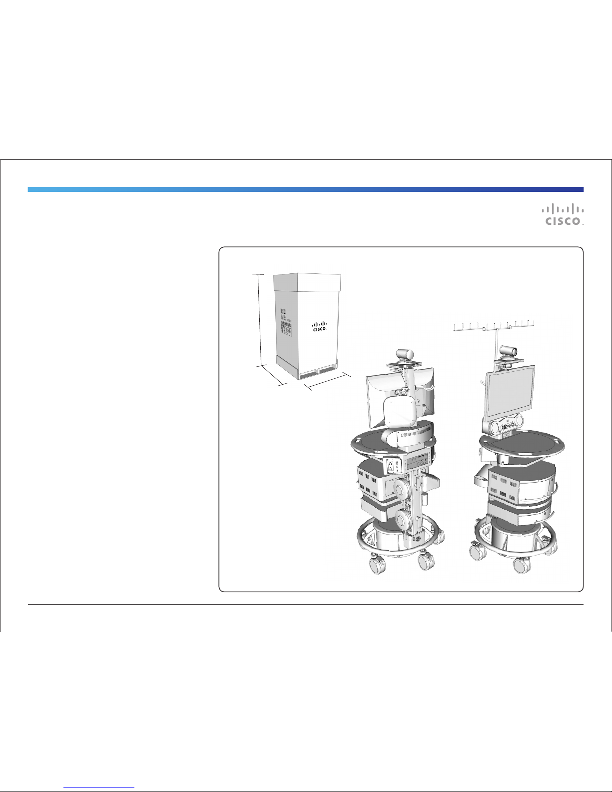
• Repacking – Do not throw away the carton and packing
materials. They make for an ideal container with which to
transport the system.
• Damaged Equipment - Unplug the apparatus from the
outlet and refer servicing to qualified personnel under the
following conditions:
- When the power cord or plug is damaged or frayed
- If liquid has been spilled or objects have fallen into the
apparatus
- If the apparatus has been exposed to rain or moisture
- If the apparatus has been subjected to excessive shock
by being dropped, or the unit has been damaged
- If the apparatus fails to operate in accordance with the
operating instructions.
Cart Handles (4x)
DO NOT PUSH OR
PULL THE UNIT
BY THE SUPPORT
COLUMN ABOVE THE
WORK SURFACE!
Use two or more
people to move the
unit over a threshold.
Follow instructions
for use. / Suivez les
instructions d’utilisation.

141299.21 Cisco TelePresence VX Clinical AssistantTM CTS-CA2-K9/CTS-CA2-P240V-K9 v1.2 | 2013 JAN | © 2012-2013 Cisco Systems, Inc. All rights reserved. 8
Warnings
Not Intended For Dialing Emergency
Medical Services
The VX Clinical Assistant is not intended to make
emergency calls. In the event of an emergency, the
user should use a telephone or device other than the
Cisco Telepresence VX Clinical Assistant™ to call local
emergency services.
Improper Transport Methods
When transporting the mobile cart over an obstacle
greater than 10 mm, it is recommended that 2 people
assist in the transport. The preferred method is to
backing the rear wheels over the threshold and then
rotating such that the front two wheels are not both
elevated off the ground at the same time while the front
of the cart is being tipped over the threshold. There
are handles on the work surface designed for assisting
in moving and will serve as the fixed transport position.
There will be a “Do Not Push” label place on a visible
area of the front of the cart. Label information will be in
the User Guide.
Please refer to the Cisco TelePresence VX Clinical
Assistant ™ (VXCA) Installation and User Guide
under “Operator Safety Summary” and “Important
Safeguards. See http://www.cisco.com/en/US/
products/ps12152/tsd_products_support_series_
home.html.
Loss of Connectivity
During the use of the VX Clinical Assistant, a
healthcare professional may lose connectivity with the
system. Loss of connectivity can result from power
outages, network outages, failure in the VX Clinical
Assistant software/hardware, or other causes. Loss
of connectivity can prevent a health care professional
from completing a patient session in a timely manner.
In cases where time is critical, the user should not
use the VX Clinical Assistant and seek an in-person
examination from a licensed health care professional.
Delay or Choppiness of Audio or Video
Transmission
The VX Clinical Assistant may operate at a delay of up
to 150 milliseconds, depending on network condition.
This means that the provider may experience the
audio and video transmissions later then they are really
occurring. In cases where the remote health care
provider needs to make time sensitive assessments or
give instructions this delay may result in misalignment
of audio and visual transmissions to the real-time
procedure and/or inappropriate treatment or diagnosis.
Proper Training Is Required
Healthcare professionals using the VX Clinical Assistant
should be sufficiently trained and familiar with the
Installation and User Guide and the instructions for
use. Please refer to the Cisco Telepresence VX
Clinical Assistant™ Installation and User Guide (under
“Troubleshooting & Frequently Asked Questions,”
“Safety Precautions” and “Operator Safety Precaution.”
See http://www.cisco.com/en/US/products/
ps11417/tsd_products_support_install_and_
upgrade.html.
Camera May Not Focus
There may be times when the system’s main camera
or a connected peripheral camera does not focus or
loses focus. This problem can result from equipment
malfunction, improper use of the camera, improper
configuration, or other reasons. An improperly
configured or poorly focused camera may reduce the
quality of the image. The camera can be maximized on
the inputs on frame rate and resolution. Please refer
to the Cisco TelePresence System Codec C Series
“Getting Started Guide” at http://www.cisco.com/en/
US/products/ps11422/prod_installation_guides_list.
html.
Audio Distortions
The VX Clinical Assistant can experience audio
distortions due to network latency, software/hardware
malfunction, insufficient bandwidth, or for other
reasons. If audio is not of sufficient quality for the
intended use of the VX Clinical Assistant, please refer
to the Cisco Telepresence VX Clinical Assistant™
Installation and User Guide (under ”Source Controls,”
“Technical Specifications,” and “Troubleshooting
& Frequently Asked Questions.” See http://www.
cisco.com/en/US/products/ps11417/tsd_products_
support_install_and_upgrade.html.
PAL-N Video Signal Not Available
The PAL-N standard video signal is not available on the
VX Clinical Assistant.

141299.21 Cisco TelePresence VX Clinical AssistantTM CTS-CA2-K9/CTS-CA2-P240V-K9 v1.2 | 2013 JAN | © 2012-2013 Cisco Systems, Inc. All rights reserved. 9
System Assembly
The VX Clinical AssistantTM comes fully assembled with
the exception of the Cisco PrecisionHD Camera, any
optional accessories, and some cable connections.
• Cisco PrecisionHD 4xS2 Camera (or 12x option)
• Rechargeable Battery
OPTIONS:
• Locking Drawer
• Locking PC/Switch Cabinet
• PC Shelf
• Laptop Tray
• Storage Pod
• Retractable AC Cord Caddy
• Retractable Network Cable Caddy
• Scope Hooks (2)
• Splash Cover
• Wireless Access Point Mount
Tools Required for Assembly
There are no tools required for the base cart
configuration.
A Phillips Screwdriver will be needed for installing PHD
Camera and some optional accessories.
- Locking Drawer
- Locking PC/Switch Cabinet
PC Shelf
Retractable Cord Caddy
- AC Power option
- Network cable option
Scope Hooks
Splash Cover
Wireless Access
Point Mount
Laptop Tray
Storage Pod

141299.21 Cisco TelePresence VX Clinical AssistantTM CTS-CA2-K9/CTS-CA2-P240V-K9 v1.2 | 2013 JAN | © 2012-2013 Cisco Systems, Inc. All rights reserved. 10
Installing the Cisco PrecisionHD Camera
1. Reach behind the mounted DISPLAY to remove the
THUMBSCREW and COVERPLATE just under the
camera mounting surface.
2. Secure the PRECISIONHD CAMERA to the
CAMERA SHELF using the THUMBSCREW from
the camera mounting surface.
3. Replace the COVER PLATE with THUMBSCREW.
4. Connect the camera cables to the camera. The
cable slack can be stored within the column as
desired:
PHD 4xS2: Requires Camera Adapter Cable,
which extends from cables provided in column, to
the camera.
PHD 12x: Uses cables provided in the column --
no adapter required.
Coverplate
Display
PHD Camera
Camera Cables
(to PHD 4xS2 Camera
Adapter Cables or directly
to PHD 12x Camera)
Thumbscrews
CAMERA ADAPTER CABLE
FOR PHD 4xS2
CAMERA
CONTROL
CUSTOM
HDMI
PHD 4xS2 PHD 12x
(optional)
HDMI
VIDEO OUT
CAMERA
ADAPTER
CABLE
CAMERA CABLES
WITHIN COLUMN
CAMERA CABLES
WITHIN COLUMN

141299.21 Cisco TelePresence VX Clinical AssistantTM CTS-CA2-K9/CTS-CA2-P240V-K9 v1.2 | 2013 JAN | © 2012-2013 Cisco Systems, Inc. All rights reserved. 11
Installing the Rechargeable Battery
The system’s rechargeable battery is disconnected for
shipping and must be connected for proper operation.
NOTE: Ensure AC Power is not connected to the cart
when installing the battery.
1. Remove the ACCESS PANEL on the lower column
by unscrewing the THUMBSCREW (1) near the top
of the plate.
2. Remove the WING NUT (1) holding the BASE PLATE
in place.
3. Remove the BASE PLATE by gently pulling the plate
forward and then up.
4. Locate the YELLOW BATTERY CONNECTOR that
extends from the battery and plug into the POWER
SUPPLY UNIT.
5. Replace the BASE PLATE and the ACCESS PANEL.
If the BATTERY has enough charge, then the VX Clinical
Assistant is ready to be configured and begin making
calls.
If the BATTERY does not have enough charge, provide
power by plugging the system into an appropriate
outlet (120V or 240V) -- this charges the BATTERY
while powering the system with AC power.
It is recommended that the unit is initially charged 4-6
hours or until the batter meter indicates a full charge.
Make sure the display is ON if it has not turned on
automatically.
NOTE: Providing power to the system via the AC
power cord will automatically switch the system from
battery power to AC power; the battery power will
shut o and will begin to charge from the AC power.
Ensure the POWER SWITCH is in the OFF position
when connecting to AC power, and then switch to the
ON position to use AC power and charge the battery.
BATTERY MAINTENANCE: To insure maximum longevity
of the battery, the VX Clinical Assistant should periodi-
cally be operated on battery power until the “Low Bat-
tery ” warning comes on. Once the warning sounds the
system should be reconnected to an AC power source
until the battery is fully charged.
50A FUSE
(Field Replaceable -- see
Troubleshooting Section)
BATTERY CONNECTOR
ACCESS PANEL
BASE PLATE

141299.21 Cisco TelePresence VX Clinical AssistantTM CTS-CA2-K9/CTS-CA2-P240V-K9 v1.2 | 2013 JAN | © 2012-2013 Cisco Systems, Inc. All rights reserved. 12
Installing Options
The following describes how the storage options are
installed. While some items are easily installed without
the need for any tools, there are some that will require
a screwdriver and minor assembly.
Drawer Module, PC Cabinet Module, PC
Shelf, and Storage Pods
Determine the desired location(s) of the optional
DRAWER, CABINET, SHELVES, or BINS.
• Align and insert the set of hooks, at the back of
each module, to the SUPPORT COLUMN.
• Slide in to hook
• Press down to secure
• Verify locking mechanism on the upper-right hook of
the accessory has “clicked” in place.
TO REMOVE an accessory:
• PULL and HOLD the LOCK RELEASE TAB on the
upper-right hook of the accessory
• LIFT and PULL the accessory away from the column.
MAXIMUM WEIGHT CONSIDERATIONS
Locking Drawer: 15lbs / 6.8kg
PC Cabinet: 25lbs / 11.3kg
Laptop Tray: 8lbs / 3.6kg
PC Shelf: 10lbs / 4.5kg
Storage Pod: 5lbs / 2.3kg
Scope Hook: 3lbs / 1.3kg
Mounting
Hooks
Lock
Release Tab
PULL

141299.21 Cisco TelePresence VX Clinical AssistantTM CTS-CA2-K9/CTS-CA2-P240V-K9 v1.2 | 2013 JAN | © 2012-2013 Cisco Systems, Inc. All rights reserved. 13
Installing Options
Laptop Shelf
1. Remove the WORK SURFACE
• Unscrew the screw at bottom of WORK SURFACE
• Lift and pull the WORK SURFACE from the system
to remove.
• If needed, flip the codec up to gain access to the
side holes for mounting the shelf by removing the
small Phillips screw at the bottom of the codec
shelf.
2. Mount the LAPTOP SHELF to the system with the
supplied screws (4) as shown.
To operate the LAPTOP SHELF, pull the knob to release
the tray’s locking mechanism and slowly swing the tray
to lock in the closed position (under the work surface)
or in the extended position.
CAUTION: During adjustment of laptop tray, the spring-
loaded knob may pinch finger if the knob is grasped
beyond the knob’s head, and pinching may occur while
the tray is adjusted.
1
2

141299.21 Cisco TelePresence VX Clinical AssistantTM CTS-CA2-K9/CTS-CA2-P240V-K9 v1.2 | 2013 JAN | © 2012-2013 Cisco Systems, Inc. All rights reserved. 14
Installing Options
To properly mount the optional SCOPE HOOKS,
WIRELESS ACCESS POINT MOUNT, and SPLASH
GUARD, remove the BACK PANEL of the MONITOR
SUPPORT COLUMN by removing the THUMB SCREW
located at the top of the support column. This provides
access to mount the options.
Each of these options are installed using the provided
WING NUTS.
Replace the BACK PANEL when finished.
Scope Hooks
Use the provided WING NUTS to mount the scope
hooks to the column as shown.
Wireless Access Point Mount
Mount the WIRELESS MOUNTING BRACKET to the
column using the provided WING NUTS.
Secure the Cisco Wireless Access Point, or similar,
to the mounting bracket, as shown, by aligning the
mounting pegs to the bracket.
Splash Cover
Mount the splash cover’s BRACKET to the MONITOR
SUPPORT COLUMN with the provided WING NUTS.
Secure the SPLASH COVER to the BRACKET.
Hang the transparent, plastic guard, as needed, onto
the posts atop the SPLASH COVER.
Scope Hooks
Splash Cover
and Bracket
Thumb Screw
for Back Panel
of Monitor
Support
Column
Back Panel of Monitor
Support Column
Wireless
Mounting
Bracket

141299.21 Cisco TelePresence VX Clinical AssistantTM CTS-CA2-K9/CTS-CA2-P240V-K9 v1.2 | 2013 JAN | © 2012-2013 Cisco Systems, Inc. All rights reserved. 15
Installing Options
Retractable AC Cord Caddy
This option is available for North America ONLY.
1. Insert the MOUNTING BRACKETS to the side of the
SUPPORT COLUMN as shown.
2. Position the RETRACTOR HOUSING to fit the flanges
over the screws of the MOUNTING BRACKETS.
3. Secure the RETRACTOR HOUSING with the
FASTENING KNOBS.
4. Remove the existing power cord by unscrewing the
CORD STRAIN RELIEF and replace with the power
cord from the rear of the RETRACTOR HOUSING.
5. Secure the CORD STRAIN RELIEF over the power
cord with an appropriate amount of slack.
6. Pull and plug the retractable cable into an
appropriate outlet to provide AC power to the
system.
To retract the power cord, unplug from outlet, gently
tug on cable to retract into the housing.
Retractable Network Cord Caddy
This option installs similarly as the AC Cord Caddy
option. Once it is mounted to the cart:
1. Connect the loose end of the cable to the
NETWORK port on the rear of the cart. If using an
optional switch, connect to the switch instead.
2. Connect the retractable end of the cable to an
appropriate network source.
TO OUTLET
CORD
STRAIN
RELIEF
FASTENING
KNOBS (2x)
RETRACTOR
HOUSING
MOUNTING
BRACKETS
TO IEC INLET
SUPPORT
COLUMN
1
2
3
4
6
5

141299.21 Cisco TelePresence VX Clinical AssistantTM CTS-CA2-K9/CTS-CA2-P240V-K9 v1.2 | 2013 JAN | © 2012-2013 Cisco Systems, Inc. All rights reserved. 16
Installing Options
PC Cabinet with Switch
The locking PC CABINET option provides a shelf to
mount and house an optional network switch to provide
greater network flexibility.
1. Attach the ANGLE BRACKETS to the sides of the
SWITCH with the provided THUMB SCREWS.
2. Align and mount the SWITCH to the SHELF with
the provided WING NUTS.
3. Insert the SHELF with the mounted SWITCH into
the PC CABINET.
4. Secure the SHELF to the PC CABINET with the
provided WING NUTS.
Use the rear ACCESS PANELS for cable management.
CAUTION: Remove the locking KEY when moving the
VX Clinical Assistant. Failure to remove the key may
result in damaging the key, damaging other equipment,
or personal injury.
1
2
3
4

141299.21 Cisco TelePresence VX Clinical AssistantTM CTS-CA2-K9/CTS-CA2-P240V-K9 v1.2 | 2013 JAN | © 2012-2013 Cisco Systems, Inc. All rights reserved. 17
Installing Optional Network Switch
If additional network ports are requires, mount a network switch into the PC Cabinet
(see PC Cabinet with Switch). NOTE: Power to the cart should be removed
before installing the WAP or switch.
1. Mount the Power Supply for the Switch into the
base of the cart, up against the system’s Isolation
Transformer, and plug into the provided Power Bar.
2. Run the Switch’s Power Cable up through the
column and plug into the Switch housed inside the
PC Cabinet.
3. Route a supplied Network Cable from the
NETWORK port on the rear of the cart to the rear
of the PC Cabinet and plug into the Switch.
NOTE: Clip the Network
Cable to the Strain Relief
Clip at the bottom right
corner of the interface place
with the NETWORK port.
4. Connect a Network Cable
from the Switch to an
appropriate network source.
NOTE: If using the optional
Retractable Network Caddy,
connect the loose end of the
cable to the Switch, and connect
the retractable end of the
cable to an appropriate
network source.
5. Make the appropriate
network configurations per
the requirements of your
organization.
Installing Options
Installing Optional Wireless Access Point (WAP)
If wireless network connectivity is required, mount a
wireless access point (WAP) securely to the cart (see
Wireless Access Point Mount). NOTE: Power to the
cart should be removed before installing the WAP or
switch.
1. If required, install the Power Injector into the base
of the cart, up against the system’s Isolation
Transformer, and plug into the provided Power Bar.
2. Use the integrated Network Cable, available inside
the column, to connect the WAP and the “AP”
(Access Point) port on the Power Injector.
3. Connect a supplied Network Cable from the
“Switch” port on the Power Injector to the
NETWORK port on the rear
of the VX Clinical Assistant.
NOTE: Clip the Network
Cable to the Strain Relief
Clip at the bottom right
corner of the interface place
with the NETWORK port.
4. Make the appropriate
network configurations per
the requirements of your
organization.
POWER for
SWITCH
to POWER BAR
inside BASE
NETWORK
SWITCH
Optional Retractable
Network Caddy
Strain
Relief Clip
POWER
INJECTOR
to POWER BAR
inside BASE
ACCESS
POINT
SWITCH
WAP
Strain
Relief Clip
Integrated
Network Cable

141299.21 Cisco TelePresence VX Clinical AssistantTM CTS-CA2-K9/CTS-CA2-P240V-K9 v1.2 | 2013 JAN | © 2012-2013 Cisco Systems, Inc. All rights reserved. 18
Installing Options
Installing Optional WAP and Switch
NOTE: Power to the cart should be removed before
installing the WAP or switch.
1. Mount the Power Supply for the Switch into the
base of the system and plug into the provided
Power Bar.
2. Run the Switch’s Power Cable up through the
column and plug into the Switch housed inside the
PC Cabinet.
3. Reroute the integrated Network Cable, available
inside the column, up into the rear of the PC
Cabinet and plug into the Switch. Connect the
other end to the WAP.
4. Connect a supplied Network
Cable from the Switch to the
NETWORK port on the rear
of the cart.
NOTE: Clip the Network
Cable to the Strain Relief
Clip at the bottom right
corner of the interface place
with the NETWORK port.
5. Make the appropriate
network configurations per
the requirements of your
organization.
POWER for
SWITCH
to POWER BAR
inside BASE
NETWORK
SWITCH
WAP
Strain
Relief Clip
Integrated
Network Cable

141299.21 Cisco TelePresence VX Clinical AssistantTM CTS-CA2-K9/CTS-CA2-P240V-K9 v1.2 | 2013 JAN | © 2012-2013 Cisco Systems, Inc. All rights reserved. 19
Installing Options
Enabling the Dual Display Option
The VX Clinical Assistant can accommodate a second
display for an enhanced telepresence session or
presentation. An HDMI EXTENSION CABLE is made
available for easy access to connect to within the
support column.
1. Remove the ACCESS PANEL on the lower column by
unscrewing the THUMBSCREW (1) near the top of the
plate.
2. Locate the HDMI EXTENSION and securely connect the
USER SUPPLIED HDMI CABLE to the EXTENSION.
3. Replace the ACCESS PANEL while ensuring the HDMI
CABLE is able to exit the COLUMN through the egress
at the top of the ACCESS PANEL.
4. Connect the HDMI Cable to the display you intend to
use.
NOTE: Ensure power is provided to the display and is ON.
NOTE: Place the second display on a secure and stable
location to avoid damage or injury.
5. Press and hold (LAYOUT Button) on the SOURCE
CONTROL interface for five seconds to enable the Dual
Display option.
NOTE: When a second display is connected, the default
mode will present Single Display mode where the displays
are mirrored.
6. Use the SOURCE CONTROLS to present different
content on the second display.
NOTE: Turning the system off with the Power Button on
the Battery Meter Panel will revert the Dual Display setting
to Single Display mode. Placing the system on Standby
does not alter the Dual Display setting.
1
2
5
4
3

141299.21 Cisco TelePresence VX Clinical AssistantTM CTS-CA2-K9/CTS-CA2-P240V-K9 v1.2 | 2013 JAN | © 2012-2013 Cisco Systems, Inc. All rights reserved. 20
Power Schematics
Power Schematics
Audio Schematics
Video Schematics
Control Schematics
NOTE: The battery in this product is non-user replaceable
and should be removed by a service technician only.
Other manuals for TelePresence VX Clinical Assistant
1
Table of contents
Other Cisco Medical Equipment manuals
Popular Medical Equipment manuals by other brands

DENTSPLY
DENTSPLY Cavitron Prophy-Jet Directions for use

Gima
Gima LUXOR user manual

PLUSOPTIX
PLUSOPTIX S12C Software update

Symmetry Surgical
Symmetry Surgical GREENBERG manual

Weinmann
Weinmann OXYWAY Series Description of the equipment and instructions for use

Abbott
Abbott AMPLATZER TorqVue LP Instructions for use