Cisco uBR904 User manual

CHAPTER
Product Overview 1-1
1
Product Overview
This chapter provides physical and functional overviews of the Cisco uBR904 cable
modem. It contains physical descriptions of the cable modem hardware and functional
descriptions of hardware-related features.
The Cisco uBR904 cable modem is a part of a new class of Cisco data-over-cable products.
The Cisco uBR904 cable modem is a compact, easy-to-install device that can receive and
transmit digital data over hybrid fiber coaxial (HFC) cable; the same cable that brings
television broadcast transmissions into a cable television (CATV) subscriber’s home.
With a Cisco uBR904 cable modem, a personal computer can be connected to the HFC
cable network for high-speed access to the Internet. The link that enables the transmission
of two-way digital data from the HFC network to the Internet is provided by the
Cisco uBR7246 universal broadband router installed at the cable headend.
The Cisco data-over-cable products, the Cisco uBR904 cable modem and the
Cisco uBR7246 universal broadband router, are based on the Multimedia Cable Network
Partners, Ltd. (MCNS) Data Over Cable Service Interface Specification (DOCIS)
standards-based specifications. MCNS is a consortium of cable television companies
whose goal is to create standards for interoperable data-over-cable systems.
The Cisco uBR904 cable modem operates with one external AC-input power supply.
The Cisco uBR904 cable modem provides the following features:
•High-speed access to the Internet—Downstream (receive) connection speeds of up to
36 Mbps, and upstream (send) connection speeds of up to 2 Mbps
•Multicast messages—Multiple users can receive important information at the same time

Cable Modem Terminology
Cisco uBR904 Cable Modem Installation and Configuration Guide
1-2
•User data privacy—Upstream and downstream data is encrypted to provide data privacy
protection
•Downloadable software—Software and configuration information is downloaded from
the cable headend to the cable modem
Note Data-over-cable systems are capable of providing access speeds up to 36 Mbps.
That bandwidth, however, is shared by several subscribers because there are very few
computers today that can connect to a network at such high speeds. Typical connection
speeds to be expected are 5 Mbps downstream and 1 Mbps upstream.
To compare data-over-cable speeds with other Internet access technologies available
today, a file that would take eight minutes to download over standard telephone lines
with a 28.8 kbps modem would take two minutes to download over ISDN. The same file
would take approximately eight seconds to download over a data-over-cable system.
Cable Modem Terminology
CATV Originally stood for Community Antenna Television. Now refers to any cable
(coaxial/fiber) based system that provides television services.
Cable modem Any device that modulates and demodulates digital data onto a CATV plant.
Cable router A modular chassis-based router optimized for the data over CATV HFC
application.
Channel A specific frequency allocation and bandwidth. Downstream channels used for
television in the U.S. are 6 MHz wide.
CM Cable modem.
Downstream The set of frequencies used to send data from a headend to a subscriber.
Headend Central distribution point for a CATV system. Video signals are received here
from satellite (either co-located or remote), frequency converted to the
appropriate channels, combined with locally originated signals, and rebroadcast
onto the HFC plant. For a CATV data system, the headend is the typical place to
link between the HFC system and any external data networks.

Product Overview 1-3
Cable Modem Terminology
HFC Hybrid fiber-coaxial (cable). Older CATV systems were provisioned using only
coaxial cable. Modern systems use fiber transport from the headend to an optical
node located in neighborhood to reduce system noise. Coax runs from the node to
the subscriber. The fiber plant is generally a star configuration with all optical
node fibers terminating at a headend. The coaxial cable part of the system is
generally a trunk-and-branch configuration.
Host Any end-user computer system that connects to a network. In this guide, the term
host refers to computer systems connected to the LAN interface of the cable
modem.
Host Device See Host for details.
MCNS Multimedia Cable Network System Partners Ltd., a consortium of cable
companies representing the majority of homes in the U.S. and Canada who have
decided to drive a standard with the goal of having interoperable cable modems.
QAM Modulation scheme mostly used in the downstream direction (QAM-64,
QAM-256). QAM-16 is expected to be usable in the upstream direction.
Numbers indicate number of code points per symbol. Number of bits per symbol
can be computed by 2^(number of bits/symbol) = number of code points.
QPSK Modulation scheme used in the upstream direction. Supports two data bits per
symbol.
Subscriber Unit (SU) A term used for cable modems. See Cable Modem for a description.
Upstream The set of frequencies used to send data from a subscriber to the headend.

Physical Description
Cisco uBR904 Cable Modem Installation and Configuration Guide
1-4
Physical Description
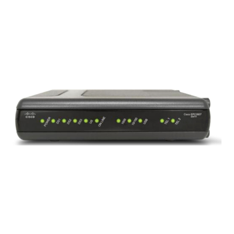
The front of the Cisco uBR904 cable modem (see Figure 1-1) provides a basic operating
status display using 16 LEDs. For a description of the LEDs, see the section,
“Troubleshooting the Power Subsystem Using LEDs” in the chapter, “Troubleshooting the
Installation.”
Figure 1-1 Cisco uBR904 Cable Modem—Front View
The rear of the Cisco uBR904 cable modem (see Figure 1-2) provides the receptacles to
connect the unit to the CATV network, a console device, and a personal computer.
Figure 1-2 Cisco uBR904 Cable Modem—Rear View
The Cisco uBR904 cable modem operates as a desktop device. Place it on a sturdy desktop
or platform near the personal computer to which it will be connected.
11578
12051
Cable F-connector
Reset
switch
Power
receptacle
Ethernet 10BaseT
(RJ-45)
Console
(RJ-45)

Product Overview 1-5
Physical Description
System Specifications
Table 1-1 lists the Cisco uBR904 cable modem physical specifications and power
requirements.
Table 1-1 Cisco uBR904 Cable Modem Physical Specifications
Description Specification
Dimensions (H x W x D) 2.30 x 13.50 x 9.30 in. (5.08cm x 34.29cm x 24.77cm)
Weight ~ 4.5 lb (~ 2.04 kg) for the Cisco uBR904
~ 0.5 lb (~ 0.23 kg) for the AC-input external power supply
AC-input voltage 120 to 240 VAC1wide input with power factor correction
1. VAC = volts alternating current.
AC-input current rating 1.2A2maximum at 120 VAC and 0.6A maximum at 240 VAC
2. A = ampere.
AC-input cable 18 AWG3three-wire cable, with a three-lead receptacle on the power supply end, and a
North American (NEMA 5-15P) plug on the power source end
3. AWG = American Wire Gauge.
Power dissipation 12 to 15W
Frequency 50/60 Hz4
4. Hz = hertz.
Temperature 23 to 113°F (0 to 40°C) operating; -13 to 95°F (-25 to 70°C) nonoperating
Humidity 5 to 95% noncondensing
Noise level 38 dBa5maximum at desktop, 43 dBa maximum in an office
5. dBa = adjusted decibels.
Software requirement Cisco uBR904 Cable Modem software and Cisco IOS Release 11.3(7) NA or later.
Agency approvals Safety: UL 1950, CSA 22.2 No. 950, EN60950
EMI: FCC Class A, FCC Class B, CSA Class A, EN60555-2, EN55022 Class B,
VCC1 Class 2, AS/NZS 3548 Class A
Immunity: IEC-1000-4-2, IEC-1000-4-3, IEC-1000-4-4, IEC-1000-4-5, IEC-1000-4-6,
IEC-1000-4-11, IEC-1000-3-2, IEC 60950, AS3260, TS001
See also the Regulatory Compliance and Safety Information for the Cisco uBR904
document.
Physical Description
Cisco uBR904 Cable Modem Installation and Configuration Guide
1-6
Note For footprint information and additional dimensions, refer to the section “Site
Requirements” in the chapter “Preparing for Installation.”
Power Supply
The Cisco uBR904 cable modem uses one external AC-input power supply. The OK
(power) LED on the front of the cable modem indicates that the power supply is supplying
power to the unit. Table 1-1 lists the AC-input power supply power specifications, including
input voltage and operating frequency ranges.
The bottom, sides, and rear of the cable modem must remain unobstructed to ensure
adequate airflow and prevent overheating inside the unit. The rubber feet on the bottom of
the cable modem provide enough clearance when the unit is placed on a flat, hard surface.
Do not place the cable modem on an uneven or soft surface. We recommend at least
3 inches of clearance at the rear of the cable modem. (See the section “Site Requirements”
in the chapter “Preparing for Installation.”)
Compliance with U.S. Export Laws and Regulations Regarding
Encryption
Cisco cable modem cards perform encryption and are regulated for export by the U.S.
Government. Following is specific information regarding compliance with U.S. export laws
and regulations for encryption products:
•Cisco cable modem cards are not authorized for use by persons located outside the
United States and Canada that do not have export license authority from the U.S.
Government.
•Cisco cable modem cards may not be exported outside the U.S. and Canada either by
physical or electronic means without the prior written approval of the U.S. Government.
•Persons outside the U.S. and Canada may not reexport, resell, or transfer Cisco cable
modem cards by either physical or electronic means without prior written approval of
the U.S. Government.

Product Overview 1-7
Functional Overview
Functional Overview
This section provides a functional overview of the Cisco uBR904 cable modem. It describes
the cable modem Media Access Control (MAC) address, connection, and configuration.
These descriptions will help you become familiar with the functions of the Cisco uBR904
cable modem.
MAC-Layer Address
All local-area network (LAN) devices, such as cable modems, require unique MAC-layer
addresses, also known as hardware addresses. The MAC address of a Cisco uBR904 cable
modem is stored in the unit. You should record the MAC address on the site installation
sheet provided in the chapter, “Preparing for Installation.”
Cisco uBR904 Cable Modem Cable Connections
The Cisco uBR904 cable modem is connected to CATV coaxial cable and to an Ethernet
port on a personal computer. The personal computer must have an Ethernet network card
installed; either an internal card installed in the computer chassis, or a PCMCIA adapter
card and cable installed on a laptop computer.
The coaxial cable connection uses standard connectors at both ends of the coaxial cable,
and an F-connector on the back of the cable modem. The F-connector is labeled
“Cable TV In.” The Ethernet connections use straight-through Ethernet cables with RJ-45
connectors at both ends, and RJ-45 receptacles on the back of the cable modem. The
RJ-45 connectors are labeled 1X, 2X, 3X, and 4X.
Note One straight-through Ethernet cable with RJ-45 connectors has been included with
your Cisco uBR904 cable modem. Additional RJ-45 cables are also available from outside
commercial cable vendors.

Functional Overview
Cisco uBR904 Cable Modem Installation and Configuration Guide
1-8
If you are connecting the Cisco uBR904 cable modem to a hub at the installation site (to
provide access to the cable modem from multiple computers), you need to use a crossover
Ethernet cable with RJ-45 connectors.
Note Crossover Ethernet cables are not available from Cisco Systems; they are available
from Cisco and outside commercial cable vendors. Optionally, you can use a straight-
through Ethernet cable and connect to the uplink port on your hub (often labeled Uplink or
MDI).
Airflow and Cooling
To keep the Cisco uBR904 cable modem operating at optimal internal temperature, keep
the bottom, sides, and rear of the cable modem clear of obstructions and away from the
exhaust of other equipment.
Other manuals for uBR904
3
Table of contents
Other Cisco Modem manuals

Cisco
Cisco SPA122 ATA User manual

Cisco
Cisco DPC3212 User manual

Cisco
Cisco Cisco 2900 series User manual

Cisco
Cisco BWX 120 User manual

Cisco
Cisco DPC2607 User manual

Cisco
Cisco EPC2203 User manual

Cisco
Cisco BWX360 WiMAX User manual

Cisco
Cisco EPC3925 User manual

Cisco
Cisco 3848 User manual

Cisco
Cisco DPC3000 User manual

Cisco
Cisco DPC2505 User manual

Cisco
Cisco DPQ2160 User manual

Cisco
Cisco DPC3208 User manual

Cisco
Cisco EPC3208G EuroDOCSIS 3.0 8x4 User manual

Cisco
Cisco DPC2203C Operating instructions

Cisco
Cisco Linksys E800 User manual

Cisco
Cisco DPC2100 User manual

Cisco
Cisco DPC3848 Instruction Manual

Cisco
Cisco DPC3848 User manual

Cisco
Cisco DPC3202 User manual