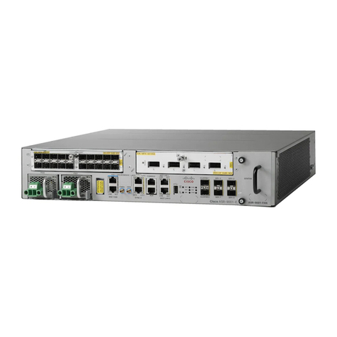
Cisco 7505 User manual

INSTALL THE HARDWARE
CONNECT THE RSP
START AND CONFIGURE THE SYSTEM
INSTALL FIELD REPLACEABLE UNITS (FRUS)
1
2
3
4
5
Quick Start Guide
Is Cisco documentation helpful? Click here or go to http://www.cisco.com/warp/public/732/docsurvey/rtg/ to
give us your feedback. CISCO 7505 ROUTER
H2761
RSP slot
DC OK LED
Power switch
Chassis
grounding
receptacles
Power receptacle AC-input power suppl
y
EJECT
SLOT 0
SLOT 1
NORMAL
CPU HALT
RESET
AUX.
CONSOLE
ROUTE SWITCH PROCESSOR
ENABLE
ENABLE
Interface processor slot 1
Interface processor slot 2
Interface processor slot 0
Interface processor slot 3


1
Install the Hardware
H2761
RSP slot
DC OK LED
Power switch
Chassis
grounding
receptacles
Power receptacle AC-input power supply
EJECT
SLOT 0
SLOT 1
NORMAL
CPU HALT
RESET
AUX.
CONSOLE
ROUTE SWITCH PROCESSOR
ENABLE
ENABLE
Interface processor slot 1
Interface processor slot 2
Interface processor slot 0
Interface processor slot 3
The Cisco 7505 has five slots: one slot for the Route
Switch Processor (RSP) and slots 0, 1, 2, and 3 for
the interface processors. The Cisco 7505 uses a
single power supply, with two models available: DC
input or AC input.
Packing List
• 1 Cisco 7505 router
• 1 Route Switch Processor (RSP)
• Y-Adapter cables, 1 auxiliary and 1 console
• 1 AC power supply
• 1 AC power supply cable
• 1 Power cord
• 1 Anti-static wrist strap and documentation

2
Prepare to Install the Router
Install the Hardware
Note For detailed hardware installation
instructions and safety guidelines, refer to the Cisco
7500 Series Router Installation and Configuration
Guide, Site Preparation and Safety Guide, and the
Cisco 7500 Regulatory Compliance and Safety
Guide.
Warning Only trained and qualified
personnel should install, replace, or service
this equipment.
Step 1 Lift the router safely out of the packing
container.
Step 2 Ensure the power service at the site is
suitable for the router you are installing.
Step 3 Check the packing slip to ensure that all
the proper components are present.
Step 4 Confirm that you have the required tools
and parts:
For rack-mounting (optional):
• Number 1 and Number 2 Phillips screwdrivers
• 1/4-inch and 3/16-inch flat-blade screwdrivers
• Tape measure
• Level (optional)
• Two chassis ears (rack brackets included with
Cisco 7505)
• Four M4 x 10-mm Phillips flathead screws to
secure the ears to the chassis (included)
• Eight 10-32 x 3/8-inch slotted binderhead
screws to secure the chassis ears to the mounting
strips (also called rails) in the rack
For cable-management brackets:
• Number 1 Phillips screwdriver
• Two cable-management brackets
• Six M3 x 8-mm Phillips panhead screws
For interface modules:
• Number 1 Phillips or 3/16-inch flat-blade
screwdriver
For DC-Input Power Supply:
• Twin-lead, 10-AWG cable terminal block
connection
• Single 10-AWG wire for the ground connection
• 3/16-inch flat-blade screwdriver

3
Rack-Mount the Router (Optional)
Install the Hardware
53373
18.312"
(46.51 cm)
hole centerline
to hole centerline
17.72" min.
(45 cm)
Ears (2) M4 x 10-mm
screws (4)
10-32 x 3/8-inch
screws (8)
Mounting strips
A
B
C
Step 1 Measure the space between the vertical
mounting strips on the rack. Confirm that
the rack conforms to the measurements
shown in A.
Step 2 Use the four M4 x 10-mm screws
provided to attach the ears to the sides of
the chassis, as shown in B. (Use two
screws per ear.)
Warning To prevent injury, two people
are required to lift the chassis. Grasp the
chassis underneath the lower edge, and lift
with both hands. To prevent injury, keep
your back straight and lift with your legs,
not your back.
Step 3 Use the eight 10-32 x 3/8-inch screws
provided to attach the ears to the
mounting strips, as shown in C. Use four
screws per ear and mounting strip.
Step 4 Level the chassis as required. Provide
two inches of clearance on either side of
the chassis.

4
Install Interface Processors, Fillers, VIPs, and RSPs
Install the Hardware
Card carrier guide (black)
Captive
installation
screw
53375
A
B
C
TheRouteSwitchProcessor(RSP)comesuninstalled
withyourCisco7505router, but is a required system
component. Install the RSP in the RSP slot, and
install any interface processors, fillers, or Versatile
Interface Processors (VIPs) in slots 0, 1, 2, and 3.
Step 1 Hold the interface processor, filler, VIP, or
RSP with one hand, and place your other
hand under the carrier to support the card
and guide it into the slot. Avoid touching
the card.
Step 2 Place the interface processor, filler, VIP, or
RSP in the slot and align the guide on the
carrier with the groove in the slot, as
shown in A.
Step 3 Carefully slide the interface processor,
filler, VIP, or RSP into the slot until the
faceplate makes contact with the ejector
levers.
Step 4 Usethethumbandforefingerofeachhand
to push the ejector levers flat against the
interface processor, filler, VIP, or RSP, as
shown in B.
Step 5 Use a screwdriver to tighten the captive
installation screws, as shown in C.
Step 6 RepeatStep 1throughStep 5toinstallthe
RSP or any additional interface
processors, fillers, or VIPs.
Note Refer to the “Check the RSP Installation”
section on page 19 to check the RSP installation.
Refer to the “Check the Interface Processor or VIP
Installation” section on page 20 to check the
interface processor or VIP installation.

5
Attach the Cable-Management Brackets
Install the Hardware
Bracket (2)
M3 screw (6)
53372
EJECT
SLOT 0
SLOT 1
NORMAL
CPU HALT
RESET
CONSOLE
ROUTE SWITCH PROCESSOR
Step 1 Place the bracket on the rear of the
chassis, as shown.
Step 2 Insert three M3 x 8-mm Phillips screws,
and tighten slightly with your finger.
Step 3 Use a Phillips Number 1 screwdriver to
tighten all three screws.
Step 4 Repeat Step 1 through Step 3 for the
second bracket.
Step 5 Route the interface cables through the
brackets.

6
Connect the Power Supply
Install the Hardware
The Cisco 7505 router supports AC-input and DC-input power supplies. The power supply is already installed
in the router when you receive it. You connect the power to it.
Note The AC-input power supply is the shipped as the default if no power supply is specified at the time of
purchase.
Connect the AC-Input Power Supply
Step 1 Push the cable retention clip away from the power supply receptacle, and push the power cable in
until the cable retention clip snaps into place.
Step 2 Connect the opposite end of the power cable to an appropriate power source.
Connect the DC-Input Power Supply
Step 1 Turn off the power source. Locate the circuit breaker on the panel board that services the DC circuit,
and switch it off, then tape the switch handle of the circuit breaker in the off position.
AC receptacle
On/off switch
Cable retention
clip
DC OK LED
H1998
DC OK LED
Terminal block
(cover removed)
H9713
On/off switch

7
Install the Hardware
Caution: Do not strain the connection at the terminal block
53422
Terminal block
cover and
captive screws
-48/-60V
20/16A —
RTN -48
POWER SUPPLY
TERM. BLOCK COVER
- USE ONLY WITH
NEC CLASS 3
WIRING
- USE COPPER
CONDUCTORS
-48/-60V
20/16A —
RTN -48
-48/-60V
20/16A —
RTN -48
POWER SUPPLY
TERM. BLOCK COVER
- USE ONLY WITH
NEC CLASS 3
WIRING
- USE COPPER
CONDUCTORS
Cable strain relief
nylon cable tie
AB
D
C
Ground
terminal
Step 2 Loosen the two captive screws that secure
the terminal block cover, as shown in A.
Step 3 Pull the terminal block cover away from
the terminal block, as shown in B.
Step 4 Feed the return (RTN) and –48V wires
through the large hole in the terminal
block cover, as shown in C.
Step 5 Attach a nylon cable tie to secure the
cables to the terminal block cover.
Step 6 Attach the RTN and –48 leads to the
terminal block, as shown in C.
Note Match the color coding at the DC source.
Typically, green or green/yellow is used for ground,
black is used for RTN, and red or white is used for
–48V.
Step 7 Attach the ground cable to the ground
terminal.
Step 8 Replace the terminal block cover, as
shown in B.
Step 9 Tightenthecaptivescrews on the terminal
block cover, as shown in A.

8
Connect the RSP
H3538
Modem
Console terminal
Auxiliary
port
Console
port
DB-25 female
DB-25 male
RSP
Connect the Console Port
The system console port on the RSP is a DB-25
receptacle DCE port for connecting a data terminal,
which allows you to configure and manage the
system. The console port is labeled Console.
Step 1 Connect the console cable from the
terminal to the console port on the RSP.
Step 2 Check your terminal’s documentation to
determine the baud rate of the terminal
you will be using.
Note The baud rate of the terminal you are using
must match the default baud rate (9600 baud).
Step 3 Setup the terminalas follows: 9600baud,
8 data bits, no parity, and 2 stop bits
(9600, 8N2).
Connect the Auxiliary Ports
The auxiliary port on the RSP is an ETA/TIA DTE
DB-25 plug to which you can attach external
equipment in order to access the router from the
network. The port is located next to the console port
on the RSP and is labeled AUX.
Step 1 Connect the cable from the auxiliary
device to the auxiliary port on the RSP.
Step 2 Check your terminal’s documentation to
determine the baud rate of the terminal.
Note The baud rate of the terminal must match the
default baud rate (9600 baud).
Step 3 Setup the terminalas follows: 9600baud,
8 data bits, no parity, and 2 stop bits
(9600, 8N2).

9
Start and Configure the System
Step 1 Check the following components to make
sure they are secure:
• Each interface processor is inserted all the way
into its slot, and the captive installation screws
are tightened.
• All interface cable connections are secured, and
any Flash memory cards are secured in their PC
slots.
• The system power cable is connected.
Step 2 Checktheconsoleterminaltomakesureit
is connected to the console port and
turned on.
Step 3 Turn the system power switch to the on (|)
position. The green AC (or DC) OK and
fan OK LEDs on each power supply
should go on. After a few seconds, the red
output fail LED will turn off.
Step 4 Listen for the system blower; you should
immediately hear it operating.
Step 5 Observe the normal LED indicator on the
RSP.Ifthisindicator is noton after system
initialization, an error has occurred. If
necessary, refer to Appendix A in the
Cisco 7500 Series Installation and
Configuration Guide.
Step 6 Wait until the system boot is complete
before attempting to verify the status of
interface processor indicators. During the
boot process, the LED indicators on most
of the interfaces go on and off in irregular
sequence.
Step 7 Observe the LED indicators on the
interfaceprocessorsin your system. When
the system boot is complete (a few
seconds), the RSP begins to initialize the
interface processors. During this
initialization, the indicators on each
interface processor behave differently
(most flash on and off).
The enabled LED on each interface
processor goes on when initialization has
been completed, and the console screen
displays a script and system banner
similar to the following:
GS Software (RSP-K ), Version 11.1(8)CA
Copyright (c) 1986-1995 by Cisco Systems, Inc.
This RSP2 is system master
Other RSP2 is not plugged in
Compiled Wed 10-May-95 11:06
Step 8 Observe the system startup banner. When
you start up the router for the first time,
the system automatically enters the setup
command facility, which determines
whichinterfacesareinstalledandprompts
you for configuration information for
each one. On the console terminal, after
the system displays the system banner and
hardware configuration, you will see the
following System Configuration Dialog
prompt:
--- System Configuration Dialog ---
At any point you may enter a questions mark
`?' for help.
Refer to the `Getting Started' Guide for
additional help.
Default settings are in square brackets `[]'.
continue with configuration dialog? [yes]:

10
Start and Configure the System
Start a Basic Configuration
Many privileged-level EXEC commands are used to
set operating parameters. To enter the
privileged-level:
Step 1 Enter the enable command at the EXEC
prompt (>), and then enter a
privileged-level password, as follows:
Router> enable
Password:
Router#
Step 2 Enter the configure terminal command to
enter configuration mode:
Router# configure terminal
Enter configuration commands, one per line.
End with CNTL/Z.
Router(config)#
Step 3 Enter the config-register value
configuration command, where value is a
hexadecimalnumberprecededby0x,asin
the following example:
Router(config)# config-register 0x010F
Step 4 Press Ctrl-Z to exit configuration mode.
Step 5 Save the new settings to NVRAM. Enter
the copy running-config startup-config
command.
Note The new settings do not take effect until the
system software is reloaded by rebooting the router.
Step 6 Enter the show version command to view
the configuration register value currently
in effect. The value is displayed on the last
line of the screen display:
Configuration register is 0x141 (will be 0x101
at next reload)
Step 7 Reboot the router, and then perform a
basic configuration using:
• AutoInstall (proceed to Step 8)
• Setup facility (proceed to the “Perform a Basic
Configuration Using Setup” section on page 11)
• Configuration mode (proceed to the “Perform a
Basic Configuration Using Configuration
Mode” section on page 13)
Note Configuration register changes take effect
only when the system reloads, such as when you
issue a reload command from the console.
Configure Using AutoInstall
Step 8 Connect to the network using a serial
(WAN) cable to the channel service
unit/data service unit (CSU/DSU).
Step 9 Contact your system administrator to
verify that the TCP/IP host on your
network is preconfigured.
Step 10 Press Ctrl-Z to exit configuration mode.
Step 11 At the # prompt, enter the copy
running-config startup-config command
to save the configuration to NVRAM as
follows:
Hostname# copy running-config startup-config
This completes the procedure for performing a basic
configuration using AutoInstall.

11
Perform a Basic Configuration Using Setup
Start and Configure the System
Note Therouter’sserial(WAN)cableshouldnotbe
connected to the CSU/DSU unless you are planning
to use AutoInstall. If you are using the console
Y-cable that shipped with your router, use either of
the two DB-25 male plug ends of the Y-cable.
Step 1 Select the protocols supported on your
interfaces. For Internet Protocol (IP)-only
installations, accept the default values. A
typical minimal configuration using IP,
IPX, and AppleTalk follows:
Configuring global parameters:
Enter host name [Router]: Router
Step 2 Enter the enable secret password and the
enable password when the following is
displayed:
The enable secret is a one-way cryptographic
secret used
instead of the enable password when it exists.
Enter enable secret: barney
The enable password is used when there is no
enable secret
and when using older software and some boot
images.
Enter enable password: betty
Step 3 Enter yes or no to accept or refuse SNMP
management:
Configure SNMP Network Management? [yes]: yes
Community string [public]:
Step 4 Enter no to refuse to enable CLNS:
Configure CLNS? [no]: no
Step 5 Enter yes to enable routing on AppleTalk
and IPX:
Configure AppleTalk? [no]: yes
Multizone networks? [no]: yes
Configure IPX? [no]: yes
Step 6 Enter no to refuse to enable Vines, XNS,
DECnet, or bridging:
Configure Vines? [no]: no
Configure XNS? [no]: no
Configure DECnet? [no]: no
Configure bridging? [no]: no
Step 7 Enter yes or press Return to configure IP,
and then select an interior routing
protocol for IP, if you are using IP routing:
Configure IP? [yes]: yes
Configure IGRP routing? [yes]: yes
Your IGRP autonomous system number [1]: 15
Step 8 At the # prompt, enter the copy
running-config startup-config command
to save the configuration to NVRAM as
follows:
Hostname# copy running-config startup-config
Note Consult your network administrator to
obtain network addresses and subnet mask
information.

12
Start and Configure the System
Configure an Ethernet Interface
Step 1 To configure your system for an Ethernet
LAN, respond to the prompts as follows,
using your own IP address and subnet
mask information:
Configuring interface parameters:
Configuring interface Ethernet0/0:
Is this interface in use? [no]: yes
Configure IP on this interface? [no]: yes
IP address for this interface: 1.1.1.10
Number of bits in subnet field [0]:
Class A network is 1.0.0.0, 0 subnet bits;
mask is 255.0.0.0
Step 2 Enter yes to enable IPX on this interface,
using the IPX network number:
Configure IPX on this interface? [no]: yes
IPX network number [2]:
Step 3 Enter yes to enable AppleTalk on this
interface, to configure for extended
AppleTalk networks, and then enter the
cable range number. Enter the zone name
and any other additional zones that will
be associated with your local zone:
Configure AppleTalk on this interface? [no]:
yes
Extended AppleTalk network? [no]: yes
AppleTalk starting cable range [0]:
Step 4 At the # prompt, enter the copy
running-config startup-config command
to save the configuration to NVRAM as
follows:
Hostname# copy running-config startup-config
Configure a Synchronous Serial
Interface
Step 1 Enter yes to configure serial port 0:
Configuring interface Serial1/0:
Is this interface in use? [no]: yes
Step 2 Determine which protocols you want to
allow on the synchronous serial interface
and enter the appropriate responses:
Configure IP unnumbered on this interface?
[no]:
IP address for this interface: 1.1.1.20
Number of bits in subnet field [0]:
Class A network is 1.0.0.0, 0 subnet bits;
mask is 255.0.0.0
Configure IPX on this interface? [no]: yes
IPX network number [2]:
Configure AppleTalk on this interface? [no]:
yes
Extended AppleTalk network? [no]:
AppleTalk network number [1]:
Step 3 Press Ctrl-Z to exit configuration mode.
Step 4 At the # prompt, enter the copy
running-config startup-config command
to save the configuration to NVRAM as
follows:
Hostname# copy running-config startup-config
YourCisco 7505 routerisnow minimally configured
and ready to use. If you want to modify the
parameters after the initial configuration, use the
setup command. To perform more complex
configurations, use the configure command. For
more information on additional interface
configuration and information on more specific
system configurations, refer to the Cisco 7500 Series
Installation and Configuration Guide.

13
Perform a Basic Configuration Using Configuration Mode
Start and Configure the System
At the reboot, the following example appears:
Any interface listed with OK? value "NO" does
not have a valid configuration.
Interface IP-Address OK? Method Status
Protocol
Ethernet0/0 unassigned NO not set down down
Serial1/0 unassigned NO not set down down
Step 1 Enter the configure terminal command at
the enable prompt to enter configuration
mode from the terminal, as follows:
Router# configure terminal
Enter configuration commands, one per line.
End with CNTL/Z.
Router(config)#
Step 2 Enter the interface type slot/port
command at the enable prompt to enter
interface configuration mode, as follows:
Router(config)# interface serial
slot/port
Router(config-if)#
Step 3 Press Ctrl-Z to exit configuration mode.
Step 4 At the # prompt, enter the copy
running-config startup-config command
to save the configuration to NVRAM as
follows:
Hostname# copy running-config startup-config
YourCisco 7505 routerisnow minimally configured
and ready to use. If you want to modify the
parameters after the initial configuration, use the
setup command. To perform more complex
configurations, use the configure command. For
more information on additional interface
configuration and information on more specific
system configurations, refer to the Cisco 7500 Series
Installation and Configuration Guide.

14
Flash Memory Cards
Install Field Replaceable Units (FRUs)
A
B
C
57301
EJECT
UP
EJECT
UP
EJECT
UP
A Flash memory card that ships with your Cisco
7505 contains the Cisco IOS software image to boot
your router. You do not need to format it.
The RSP has two PC Card slots—slot 0 and slot
1—into which you can install a Flash memory card.
PC Card slot 0 is on the top and slot 1 is on the
bottom.
Note A Flash memory card can be inserted and
removed with the system power on. Both PC Card
slots can be used at the same time.
Step 1 To eject the card, press the appropriate
eject button until the card is free of the
connector at the back of the slot.
Step 2 Removethecard from the slotandplace it
in an antistatic bag to protect it.
Step 3 Face the front panel of the RSP, and hold
theFlashmemorycardwiththeconnector
end of the card toward the slot.
Note The Flash memory card is keyed and cannot
be seated the wrong way. The eject button will not
pop out if the card is not properly inserted.
Step 4 Insert the card into the appropriate slot
until the card completely seats in the
connector at the back of the slot and the
eject button pops out toward you.
Note Thecarddoes not insert allthewayinside the
RSP; a portion of the card remains outside of the
slot. Do not attempt to force the card past this point.

15
Install Field Replaceable Units (FRUs)
Format a Flash Memory Card
Flash memory cards shipped as spare parts must be
formatted. Use only Intel Series 2+ Flash memory
cards.
Step 1 Enter format slot0: (or format slot1:) to
format the Flash memory card, as follows:
Router# format slot0:
Step 2 At the erase all sectors prompt, press
Enter to proceed.
All sectors will be erased, proceed? [confirm]
Step 3 At the volume ID prompt, enter the ID
name:
Enter volume id (up to 30 characters):
MyNewCard
Formatting sector 1
Format device slot0 completed
Router#
Copy Files to Flash Memory
To upgrade to a new Cisco IOS image, copy the
image file to Flash memory. Upgrade images one at a
time; do not delete all known good images at one
time. You cannot copy an image while the system is
running from Flash memory.
Use the command copy tftp:filename [bootflash |
slot0 |slot1]: filename for the copy procedure, where
tftp:filename is the source of the file and [bootflash |
slot0 |slot1]: filename is the destination in bootflash
memory or on either of the Flash memory cards.
An example of the copy tftp:filename command
follows for a file in the Flash memory card in PC
Card slot 0:
Router# copy tftp:myfile1 slot0:myfile1
20575008 bytes available on device slot0,
proceed? [confirm]
Address or name of remote host [1.1.1.1]?
Loading new.image from 1.1.1.1 (via
Ethernet1/0):
!!!!!!!!!!!!!!!!!!!!!!!!!!!!!![OK -
7799951/15599616 bytes]
CCCCCCCCCCCCCCCCCCCCCCCCCCCCCCCCCCCCCCCCC
Router#

16
Install Field Replaceable Units (FRUs)
Make a Flash Memory Card
Image Bootable
Note In this example, the filename is new.image,
and the Flash memory card is located in slot 0.
Step 1 Enter the configure terminal command at
the enable prompt, as follows:
Router# configure terminal
Step 2 Enter the no boot system command, as
follows.
Router(config)# no boot system
Step 3 Enter the boot system flash
slot0:new.image command, as follows:
Router(config)# boot system flash
slot0:new.image
Step 4 Enter the config-register 0x2102
command to enable loading an image
from Flash memory:
Router(config)# config-register 0x2102
Step 5 Press Ctrl-Z to exit configuration mode.
Step 6 Enter the copy running-config
startup-config command to save the
configuration to NVRAM as follows:
Hostname# copy running-config startup-config
Step 7 Enter the reload command. When the
system reloads, it will boot the image
new.image from the Flash memory card in
slot 0.
Router# reload
Enable Booting from Flash
Memory
To enable booting from Flash memory, set
configuration register bits 3, 2, 1, and 0 to a value
between 2 and 15 in conjunction with the boot
system flash device:filename configuration
command, where device is bootflash:,slot0:,or
slot1:, and filename is the name of the file from
which you want to boot the system. In the following
example, the Flash memory card is in slot 0.
Step 1 Enter the configure terminal command at
the enable prompt, as follows:
Router# configure terminal
Step 2 At the prompt, enter configuration
commands, one per line.
Enter configuration commands, one per line.
Step 3 Press Ctrl-Z to exit configuration.
Step 4 Enter the boot system flash
bootflash:slot0: filename command, as
follows:
Router(config)# boot system flash
blootflash:slot0:
filename
Step 5 Enter the config-register command with
the value shown in the following example:
Router(config)# config-reg 0x0102
Ctrl-Z
Router#
Step 6 Press Ctrl-Z to exit enable booting mode.

17
Prepare to Remove and Install an RSP
Install Field Replaceable Units (FRUs)
To remove and install an RSP, you will perform the
following steps:
• Copy the configuration file using a Trivial File
Transfer Protocol (TFTP) server
• Remove the RSP
• Install the RSP
• Connect the console terminal and ensure that it
is connected
• Turn the system power back on
• Retrieve the configuration file

18
Remove and Install an Interface Processor, Filler, VIP, or RSP
Install Field Replaceable Units (FRUs)
53376
STOP!
on contact
Bottom ejector lever
Captive
installation
screw
Card
carrier
guide
A
B
C
Card
slot
Note Do not shut down the system power when
removing an interface processor or VIP. However, if
you are removing the RSP, first copy the
configurationfiletoaTFTPserver(seethe“Copythe
Configuration File for an RSP” section on page 21),
and then return to this section to complete the
procedure.
Step 1 Attach an ESD-preventive wrist strap
between you and any unpainted chassis
surface.
Step 2 Disconnect all cables from the interface
processor, VIP, or RSP port adapters. If
you are only moving a carrier, skip this
step.
Step 3 Use a screwdriver to loosen the captive
installation screws, as shown in A.
Step 4 Place your thumbs on both ejector levers
and simultaneously pull them both
outward, as shown in B.
Step 5 Grasp the interface processor, filler, VIP,
or RSP handle with one hand and pull the
carrier straight out of the slot, keeping
yourother hand underthe carrier toguide
it.
Step 6 Store the interface processor, VIP, or RSP
in an antistatic bag.
Step 7 Repeat Step 2 through Step 6 to remove
anyadditionalinterfaceprocessors,fillers,
VIPs, or RSPs. Refer to the “Install
Interface Processors, Fillers, VIPs, and
RSPs” section on page 4 to install an
interface processor, filler, VIP, or RSP.
Table of contents
Other Cisco Network Router manuals

Cisco
Cisco ASR 9901 User manual

Cisco
Cisco 4331 User manual

Cisco
Cisco 850 Series User manual

Cisco
Cisco 7609 User manual

Cisco
Cisco 811 How to use

Cisco
Cisco ASR 907 Manual

Cisco
Cisco WS-X3011 Quick start guide

Cisco
Cisco Linksys WET610N User manual

Cisco
Cisco WRT54G User manual

Cisco
Cisco 7600 Series User manual

Cisco
Cisco 851-K9 - 851 Integrated Services Router User manual

Cisco
Cisco ASR 1013 Manual

Cisco
Cisco Router Cisco 831 How to use

Cisco
Cisco 7200 VXR Series User manual

Cisco
Cisco Linksys E1200 User instructions

Cisco
Cisco RV132W User manual

Cisco
Cisco 809 Manual

Cisco
Cisco 1712 - Security Access Router Manual

Cisco
Cisco 910 User manual

Cisco
Cisco Firepower 1120 Manual