Cisco Room Panorama User manual

Cisco Room Panorama
85INCH MAIN SCREENS
Installation guide


1
Cisco Room Panorama
The Cisco Room Panorama system is designed to make your video
conferencing room more versatile and flexible also for local meetings.
The Cisco Room Panorama is built on the Cisco
Room Kit Pro technology platform, with the Codec
Pro and the Quad Camera as core.
It has two 85-inch 8K video screens, and a 65-
inch 4K screen for content presentation.
The camera provides panorama video, speaker-
tracking, and auto-framing capabilities.
The integrated loudspeaker system consists
of twelve main loudspeakers and four bass
loudspeakers, driven by a sixteen channel
amplifier.
We recommend using the Cisco Table Microphone
Pro / Cisco Microphone Array external digital
microphones. The system supports up to six
of them, and three are shipped as default. As
an alternative, you may use up to eight analog
microphones or a full external DSP controlled
microphone solution.
In addition, integrated microphones are part of the
state of the art speaker tracking solution.
The cosmetic wall panels shown here are available
as an option.

2
Table of contents
Before you start the installation...........................................................................3
Packaging ...........................................................................................................4
Screws and tools ................................................................................................5
Installing Room Panorama with cosmetic wall panels....................................6
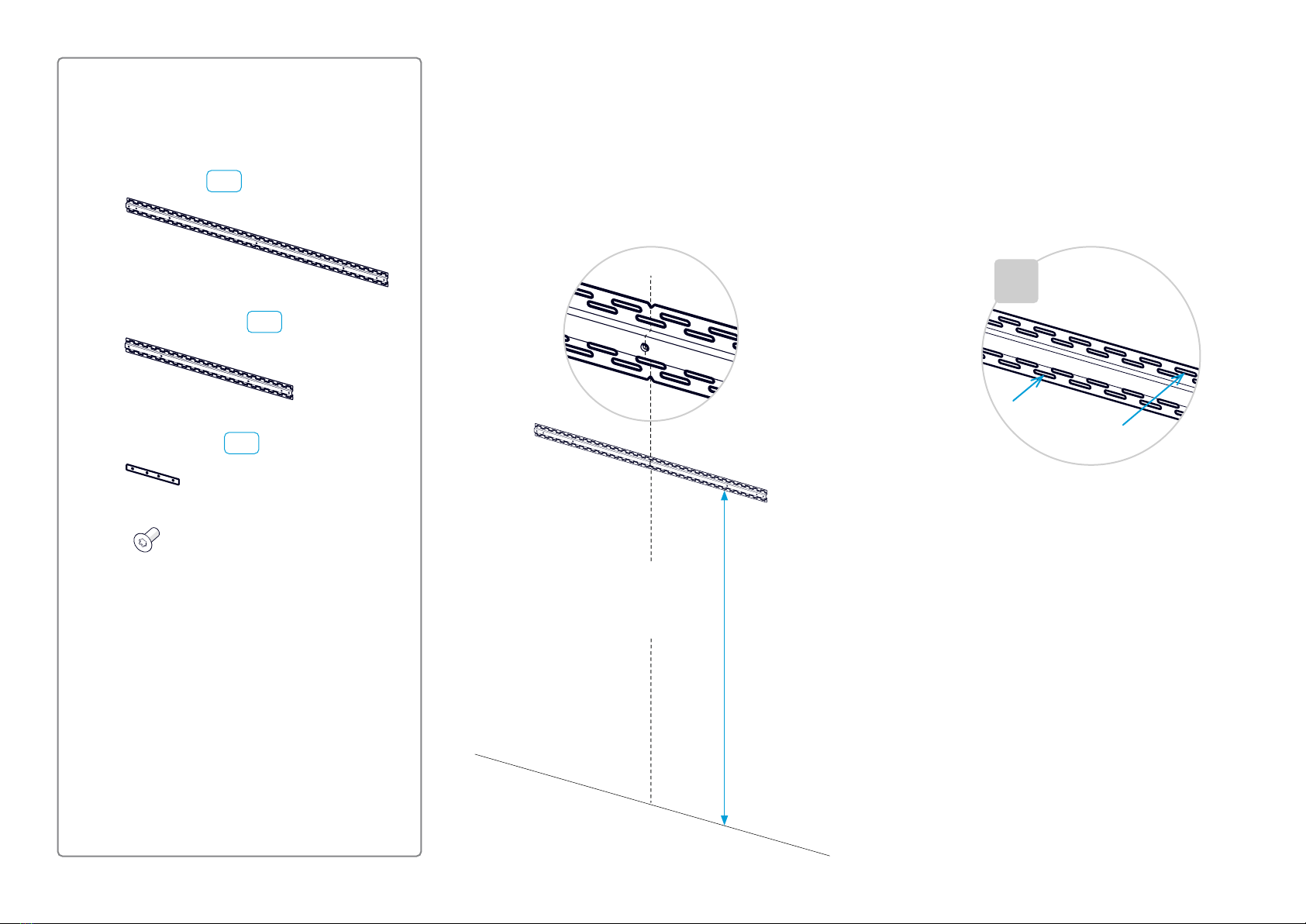
1. Fasten the horizontal rails ............................................................................7
2. Mount the vertical risers ............................................................................ 11
3. Place the subwoofers ................................................................................14
4. Mount the cavities .....................................................................................16
5. Fasten the mounting plates for the speakers.............................................20
6. Mount the PSU bracket..............................................................................22
7. Mount the codec and amplifier ..................................................................23
8. Attach the rating label................................................................................25
9. Mount the Ethernet switch .........................................................................26
10. Mount the antennas .................................................................................27
11. Mount the fan module ..............................................................................28
12. Connect cables .......................................................................................29
13. Organize the cables neatly.......................................................................33
14. Mount brackets for the cosmetic panels..................................................34
15. Mount the flex tubes for cables ...............................................................38
16. Mount the bottom trim .............................................................................40
17. Mount the upper trim................................................................................42
18. Mount the content cavity and screen mount brackets .............................44
19. Mount the cosmetic panels......................................................................46
20. Mount the camera ...................................................................................60
21. Mount the fan duct...................................................................................62
22. Mount the loudspeakers ..........................................................................63
23. Mount the content screen........................................................................66
24. Mount the right screen and deco grille ....................................................69
25. Mount the left screen and deco grille ......................................................84
26. Mount the speaker grille ..........................................................................86
27. Mount the center part of the upper trim...................................................89
28. Pull up and connect the cables between the system and components on
the table.........................................................................................................90
29. Mount the Ethernet switch in the table ....................................................91
30. Place components on the table...............................................................92
31. Finish up...................................................................................................93
Installing Room Panorama with a custom wall.............................................95
Extra requirements and preparations when building a custom wall ..................96
A1. Mount the rails and risers.......................................................................100
A2. Build the custom wall structure ............................................................100
A3. Paint visible parts of the wooden structure ..........................................102
A4. Mount the antenna support ...................................................................103
A5. Mount the flex tubes..............................................................................104
A6. Mount the custom wallboards ...............................................................105
A7. Place the subwoofers and mount the rack cavity ..................................106
A8. Complete the flex tube mounting ..........................................................106
A9. Route the antennas to the rack cavity ................................................... 107
A10. Mount the remaining cavities ...............................................................107
A11. Fasten the mounting plates for the speakers .......................................108
A12. Mount the subwoofer grille ..................................................................109
A13. Mount components.............................................................................. 110
A14. Connect the antennas.......................................................................... 110
A15. Connect and organize cables .............................................................. 111
A16. Mount the content cavity and screen mount brackets ......................... 111
A17. Mount and adjust spacers for all screens............................................. 112
A18. Mount the remaining components and grilles ...................................... 113
A19. Mount and connect the components on the table and finish up.......... 113
Connector panels ........................................................................................... 114
More information about our products ............................................................. 116

3
Before you start the installation
It is important that you read our Room Preparation
Guidelines before you start the installation. They
are available online.
During the installation you need both the
Installation Guide (this guide) and the Wiring
Diagram. The wiring diagram is shipped with the
product.
We recommend you to check if there are newer
versions of the Installation Guide and Wiring
Diagram online. You find the version number on
the last page (format: 78-xxxxxx-yyyy, where
yyyy is the version number or Dxxxxx.yy, where
yy is the version number).
Download information
You can download the room preparation
guidelines, wiring diagram, and installation
instructions from:
https://www.cisco.com/go/panorama-installation
This webpage contains installation guides for all
products in the Cisco Room Series. Look for Cisco
Room Panorama. *
Installation by instructed personnel
Due to the size and mass of the Room Panorama
system, it must be installed according to our
installation instructions by qualified personnel. The
installer must determine whether the wall must be
reinforced prior to the installation and calculate
the number and type of screws required for a safe
wall mounting.
The product is fastened to the wall
The Room Panorama is fastened to the wall with
three horizontal rails. These rails must be fastened
so that they can safely support the product. In
total, the product weighs close to 600 kg (1320 lb).
When installed correctly, the system rests on the
floor.
Perfectly flat wall
The rails must be level. If the wall is not perfectly
flat, horizontally and vertically, this must be
compensated for before you mount the rails.
The system has adjustable feet, which can
compensate for the floor not being perfectly flat.
Power
Room Panorama consists of separately approved
components. This requires each component to
be connected directly to a wall socket outlet
that is installed by a qualified electrician. You
are not allowed to use a power strip (multi-socket
extension cord).
Since each component has a power cord
connected directly to a wall socket outlet, there
is no total electrical rating (voltage, current, and
frequency) for the Room Panorama system. You
should check the rating label on each component.
Cosmetic wall
Part 1 of this guide explains how to install the
Room Panorama with the optional cosmetic wall
panels offered by us.
As an alternative to these cosmetic wall panels,
you can integrate the Room Panorama system
fully in the room by making your own custom wall
integration. This is described in Part 2.
* A new main screen model for Room Panorama was introduced in 2023. The new model is 85 inches; the original model was 82 inches. Room Panorama has the same functionality regardless of main
screen model. However, since there are a few installation and cabling differences between them, there are two sets of installation instructions and wiring diagrams online.

4
Packaging
You have received four or five pallets with parts
and components, depending on whether you have
ordered the optional cosmetic wall.
The pallets are marked with A, B, C, D, and E.
During installation, you need parts from pallet A
first.
This installation guide is on pallet A, the wiring
diagram and other information from us are on
pallet C.
Wall structure pallet Cavities pallet
Component pallet Display pallet
Cosmetic wall pallet
(optional)
Boxes and labels
There are several boxes with parts on each pallet.
The boxes are marked with a letter followed by
a number. The letter identifies the pallet. For
example A1, A2, A3, ... for the boxes on pallet A.
In general, you need box A1 before box A2, and
so on. But you don't always need all the parts
contained in a box or pallet with a lower number
before you need parts from the next.
The installation guide refers to these labels to
show where the required parts for each step are.
4x subwoofer stands
4x subwoofers
4x 50 ×50mm (2× 2 in.) piece of foam
A5
C1
A6
Example from installation guide
A
B
C
D
E
Risk of personal injury
There is a potential hazard risk tied
to the gas springs in the screen
mount modules when installing or
dismantling the system. There is
no risk involved when following the
Install Guide step by step, but if
caution is not taken regarding the
screen mount safety brackets, there
is a chance of personal injury.
To help lifting the screen with the
screen mount module, the gas
springs store a lot of energy. If the
screen mount safety brackets are
moved out of the Safe Mode position
before the screen is mounted, the
screen mount module can shoot out
at high speed, potentially causing
harm. The same goes if one tries to
remove or dismantle the gas springs
from the product.
To avoid the risk of personal injury:
• Do not disassemble any of the
pre-assembled parts of a display
cavity at any time.
• Do not move the screen mount
safety brackets out of the
Safe Mode position (transport
position) before the main screens
are mounted (refer to step 24.7).

5
Screws and tools
Required tools and equipment
• Two stepladders
• Drill
• Torx 20, Torx 25, Torx 30, and Torx 40 bits
• PH2 and PH3 bits
• Hex 2mm and 6mm bits
• Angle chuck
• Appropriate drill bits for your wall material
• Appropriate wall fasteners/anchors for your wall construction
• Laser level (multi axis)
• Small spirit level (about 25cm / 10 in.)
• Pencil
• Nylon draw tape
In addition, the installer must bring the number and type of screws required for
a safe wall mounting of the system (step 1).
1. Washer, 0.9mm (28 pcs.)
2. Nylon spacer, 5mm (16 pcs.)
3. FH M4x10, Torx 20 (24 pcs.)
4. PAN10-32x0.312, PH2 (4 pcs.)
5. M5x10, Torx 25 (12 pcs.)
6. M4x12, Torx 20 (100 pcs.)
7. M6x12, Torx 30 (150 pcs.)
8. M8x25, PH3 (8 pcs.)
9. M8x45, Hex 6mm (4 pcs.)
10.M8x8, Torx 40 (20 pcs.)
11. M4x8, Torx 20 (8 pcs.)
Screws and spacers
The following kit of screws and spacers are shipped with the product. The kit is
in box A1.
12345678
9
10
11

6
Part 1
Installing Room Panorama with cosmetic wall panels
This part of the guide explains how to install the
Room Panorama with the optional cosmetic wall
panels offered by us.
As an alternative to these cosmetic wall panels,
you can integrate the Room Panorama system
fully in the room by making your own custom wall
integration. This is described in Part 2.

7
1. Fasten the horizontal rails
Top rail
Middle rail
Bottom rail
center partleft part right part
Minimum ceiling height: 2.70 m (106.3in.)
The Room Panorama system is mounted on three
rails - top, middle, and bottom. The rails are
fastened to the wall.
The rails must be level, and accurately centered
about the system’s vertical center line. If the wall
is not perfectly flat, horizontally and vertically, this
must be compensated for before you mount the
rails.
Use a laser level to make sure the horizontal rails
are placed perfectly. This is important for the rest
of the installation process to go smooth.
Fasten the rails with the number and type of
screws that are required for a safe mounting
of the system on your type of wall. Any of the
horizontal slots in the rails can be used.
6.75 mm
(0.27 in.)
37 mm
(1.46 in.)
37 mm
(1.46 in.)
See the mounting details and exact rail positions
on the following pages.
Panorama system vertical center line

8
6x
24x
(FH M4x10, Torx 20)
You also need the number and
type of screws that are required
for fastening the rails safely to the
wall (not provided by Cisco).
joining bracket
1. Start with the center part, and find the position
of the upper rail.
The distance from the floor to the lower edge
of the rail is shown in the illustration.
Rail parts
1.1. Fasten the top rail
×n
3x center part A1
A2
6x left and right parts A2
2. Fasten the center part of the rail to the wall.
Use the type and number of screws that are
required to support the system. You can use
any of the horizontal slots in the rails.
2.60 m (102.4in.)
Center line

9
×2
×2
3. Fasten a joining bracket on each side of the
center rail (FH M4x10, Torx 20).
4. Fasten the left and right part of the rail to
the center part.
Depending on the type of wall, you may
need to remove the part temporarily after
marking the mounting points on the wall.
5. Fasten the left and right parts of the rail
to the wall.
Use the type and number of screws that
are required to support the system. You
can use any of the horizontal slots in the
rails.
×n

10
1.2. Fasten the middle rail
Use the same procedure as for the upper rail, but
measure the distance from the upper rail and not
from the floor.
The distance between the lower edges of the
upper and middle rails is shown in the illustration.
1.3. Fasten the bottom rail
Use the same procedure as for the upper rail, but
measure the distance from the middle rail and not
from the floor.
The distance between the lower edges of the
middle and bottom rails is shown in the illustration.
Remember that all rails must be level,
and accurately centered around the system’s vertical center line.
1.40 m (55.1 in.)
1.05 m (41.3 in.)

11
2. Mount the vertical risers 2.1. Assemble the risers
Enter the upper part into the lower part, and fasten with two screws (M6x12, Torx 30). Repeat for all the risers.
6x
6x 35x
(M6x12, Torx 30)
lower parts
upper part
Riser parts
1x upper part, center
The system has seven vertical risers, which are
attached to the rails. The center riser differs from
the others; it has a setback to make space for the
content screen
Center riser (1x) Other risers (6x)
Slots on this side (away from the wall)
A3
A4
B2
B1
1x lower parts

12
2.2. Fasten the risers to the rails
The risers are fastened to the rails with screws (M6x12, Torx 30), one in each rail.
Repeat the same procedure to fasten the seven risers.
1. Enter a screw into the top rail,
without tightening.
There is one screw for each
riser as shown in the illustration
to the left.
2. Hang a riser onto the screw.
The riser with a setback shall be
at center.
Check that the riser hangs on
the screw, and doesn’t rest on
the floor.
3. Fasten the riser to the middle
rail with a screw. Don't tighten
the screw now.
4. Fasten the riser to the bottom
rail with a screw. Don't tighten
the screw now.

13
5. Temporarily adjust the foot on
the riser, so that the riser rests
on the floor. Do not tighten the
upper nut to lock its position
now.
8. Tighten the screws that fasten
the risers to the rails. Three
screws on each riser (entered in
step 1, 3 and 4).
6. Repeat steps 1-5 for all risers.
Level
7. Adjust the feet to make the risers perfectly aligned
horizontally while resting on the floor. Use the laser level.
9. Re-adjust the feet, if necessary, to make them
tight against the floor. Make sure to keep all
risers aligned. Tighten the upper nuts to lock
the position of the feet.

14
3. Place the subwoofers
Subwoofers and subwoofer stands
The system has four subwoofers. They are placed
in stands on the floor. Repeat the same procedure
for all stands and subwoofers.
3.1. Place the subwoofer stands
4x subwoofer stands
4x subwoofers
4x 50 × 50 mm (2× 2 in.) piece of foam
×4 Place the stands as far to the
front as possible.
Check that the metal does not
touch the risers. Such contact
may cause rattling noise.
A5
C1
A6

15
3.2. Place the subwoofers in the stands
×4
×4
Push the subwoofer all the way down into the stand.
Check that the foam doesn't curl when pushing it down.
Note that - counting from the left:
• Subwoofer number 1 and 3: Black finish facing the room
• Subwoofer number 2 and 4: Silver finish facing the room
Black finish facing
the room
Silver finish facing
the room
Add a piece of foam - 50 ×50 mm (2 ×2 in.) - on the
upper part of the subwoofer to prevent it from touching
the riser and cause rattling noise.
Add a piece of foam
on the subwoofer to
prevent noise

16
4. Mount the cavities
Cavities
The system has six cavities, which are designed
for mounting the two main screens and the
equipment behind them.
A cavity fits between two vertical risers. It hangs
on the risers, and is secured with four screws.
We recommend you to insert the cavities close to
the center first, and the display cavities last.
1x rack cavity
2x power cavity
1x cooling cavity
2x display cavity
24x
(M6x12, Torx 30)
Hang the cavity between the two risers as shown
in the illustration. Check that the hooks fully enter
all slots on both sides (see details on the next
page).
The top of the cavity aligns with the setback of the
center riser.
4.1. Insert the rack cavity
B3
B5
B4
B6
B7
1.0m
(39.4 in.)
Side view

17
There are hooks along both sides of the cavities.
Hook all of them into the corresponding slots on
the risers. Check that they fully enter all slots on
both sides.
Hook in place in the slot.
4.2. Insert the cooling cavity
Hang the cavity between the risers as shown. The top of the cavity aligns with
the rack cavity.

18
×2
Hang the two display cavities between the risers as shown. They are identical.
The top of the cavities aligns with the rack cavity.
Hang the two power cavities between the risers as shown. They are identical.
The top of the cavities aligns with the rack cavity.
×2
4.3. Insert the power cavities 4.4. Insert the display cavities
To avoid the risk of
personal injury, do not
disassemble any of the
pre-assembled parts of
a display cavity.
Table of contents
Other Cisco Projection Screen manuals