Dear Customers:
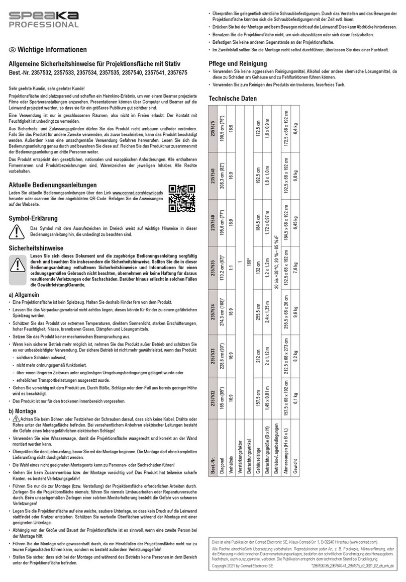
Thank you for purchasing a Grandview projection screen.
Before use, please read instruction carefully. After installation,
please store instruction for future reference.
Φ5x40 tapping screw X 8 pcs
Expansi pcs
Preparation for installation
Accessories pack:
Locking Plug x 2 pcs M5*10 Flat Head Screw x 4pcs
Ceiling hanging
bracket x 2pcs
Motor limit
setting tool X 1 pcs
Floating
Bracket X 2 pcs
Wall/Ceiling installation method
Install bracket onto wall/ceiling that
can bear such weight, and keep
screen two sides on a same level.
(Distance from casing end with
10cm), as be
Mark a cleanable level line
Loosen the down screw until the screw can cover the casing,
gure:
Hold the casing two end tly onto the bracket then push
into the bracket, when the locking toot will hear a
locking sound that means screen alread acket
safely. Lock screw an scree
Up locking
tooth
Down
locking
tooth
Ru
purpose
The button
for uninstall
screen
Note:When takin een, loosen the bottom screw t
and push the top loosen button, then you can easily take the
scree
Ceiling hanging method:
Insert the locking plug into the hole of the ceiling hanging bracket.
Use ceiling hanging bracket lock into the rut and it has a hanging
Take reference same as wall/ceiling installation, measure
installation distance and mark position, th screen casing
steady with bracket.
According to site installation height, install hook onto ceiling,
then hang the screen through bracket hol
Warning:
Before operate screen, make sure the sticker on casing and
under bar is removed.
Importance:
Fabric control instruction
Intelligent motorized screen has 4
control options:
A. Manual control (cycle control button)
B. IR control or RF control
C. Dry contact control
D. RS485 or RS232 control
A. Manual control:
Manual control button is on the left side of the casing (close to
RS485 and dry contact interface), this is a cycle control button.
B. -MI for IR: AC127 / -MF for RF: AC123
UP : screen UP
STOP: screen STOP
DOWN: screen DOWN
Mirco-up: retract the screen in small
increment
Mirco-down: lower the screen in
small increment
IR: transfer signal by IR
(Wavelength: 940Nm)
RF: Pre-set in factory; transfer signal by Radio wave(868MHz).
Programming code setting:
Screen connects to power within 10 seconds (in programming mode),
press the UP & STOP buttons together on the remote. Pairing completed.
RS485/RS232 port setting:
Baud Rate: 2400
Data Bits: 8
Odd-even check: None
Stop bits: 1
Hexadecimal control code:
Up
Down
Some central control need
to reset address cod
ee ee aa
Notice:
While connecting the RS 232 or RS485, if after plug in still can’t control
screen for operation, you may need to exchange the two control wire.
P1
DB 9
1
6
2
7
3
5
TX D
GND
8P 8C
8
4
9
USB Serial Port (COM3) Property
Detail Event
Drive Program
General Port
Confirm
Advanced Restore
Baud Rate: 2400
Data Bits: 8
Parity: None
Stop Bits: 1
Flow Control: None
Cancel
Screw to lock Lock piece
Please prepare for suitable tools such as gradienter, tape,
marker, etc.
Please make sure precise installation distance and proper
installation position for upper and nether mounting brackets.
Use the proper screws for installation according to the site.
(use tapping screws for wooden wall and tapping screws with
expaoncrete wall)
After installation, screen left and right side ensu and level.
Please make sure the installation position (ceiling or wall) or hang
device ca least 25KG, otherwise it may cause danger.
The product is using single-phase AC power, please use a socket
with earth wire and make sure the earth wire is well connected.
For in-line switch motorized screen, if necessary equip with extra
high voltage control, please must operate by a professional
engineer, and make sure central control between screen retract
and screen expand has timing delay device.(0.2 second at least)
Power Connect:
Grandview screen will pre-equip with standard plug for your
local market, only just connect plug to the socket, you can
enjoy the use of Grandview screen immediately.
D.
C.
R
Dry Contact control
S485 or RS232 control:
C
Output control connected to plug RJ45. Starting from
the left, line No. 4.5,7,8 is controlling line.
onnect the 8P8C wire through RJ45 interface,
count from left side,1~2 is control wire for RS485
control. 1 is D-, 2 is D+. RS 23
Loop resistance is under 20Ω.
Can’t work besides high voltage wire.
Line No 4 5 7 8
Function Public
Line Down Stop Up
Stop
Stop
Retract Expand
Cycle control Manual control
Rs485 and dry
contact inter face
Open the cover
of the casing
Programming code Clearing:
Screen connects to power within 10 seconds (in programming mode),
press the UP & STOP buttons together on the remote. Clearing completed.
8
7
6
5
4
3
2
1
