manuals.online logo
Brands
  1. Home
  2. •
  3. Brands
  4. •
  5. Cisco
  6. •
  7. Wireless Router
  8. •
  9. Cisco 6000 series Manual

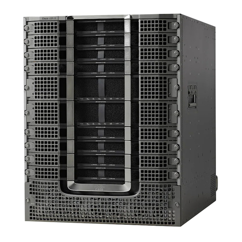
Cisco 6000 series Manual

Cisco Systems, Inc.
www.cisco.com
Cisco has more than 200 offices worldwide.
Addresses, phone numbers, and fax numbers
are listed on the Cisco website at
www.cisco.com/go/offices.
Cisco Network Convergence System
6000 Series Routers
Hardware Installation Guide
January 2014
Text Part Number: OL-29234-02
THE SPECIFICATIONS AND INFORMATION REGARDING THE PRODUCTS IN THIS MANUAL ARE SUBJECT TO CHANGE WITHOUT NOTICE. ALL
STATEMENTS, INFORMATION, AND RECOMMENDATIONS IN THIS MANUAL ARE BELIEVED TO BE ACCURATE BUT ARE PRESENTED WITHOUT
WARRANTY OF ANY KIND, EXPRESS OR IMPLIED. USERS MUST TAKE FULL RESPONSIBILITY FOR THEIR APPLICATION OF ANY PRODUCTS.
THE SOFTWARE LICENSE AND LIMITED WARRANTY FOR THE ACCOMPANYING PRODUCT ARE SET FORTH IN THE INFORMATION PACKET THAT
SHIPPED WITH THE PRODUCT AND ARE INCORPORATED HEREIN BY THIS REFERENCE. IF YOU ARE UNABLE TO LOCATE THE SOFTWARE LICENSE
OR LIMITED WARRANTY, CONTACT YOUR CISCO REPRESENTATIVE FOR A COPY.
The following information is for FCC compliance of Class A devices: This equipment has been tested and found to comply with the limits for a Class A digital device, pursuant
to part 15 of the FCC rules. These limits are designed to provide reasonable protection against harmful interference when the equipment is operated in a commercial
environment. This equipment generates, uses, and can radiate radio-frequency energy and, if not installed and used in accordance with the instruction manual, may cause
harmful interference to radio communications. Operation of this equipment in a residential area is likely to cause harmful interference, in which case users will be required
to correct the interference at their own expense.
The following information is for FCC compliance of Class B devices: The equipment described in this manual generates and may radiate radio-frequency energy. If it is not
installed in accordance with Cisco’s installation instructions, it may cause interference with radio and television reception. This equipment has been tested and found to
comply with the limits for a Class B digital device in accordance with the specifications in part 15 of the FCC rules. These specifications are designed to provide reasonable
protection against such interference in a residential installation. However, there is no guarantee that interference will not occur in a particular installation.
Modifying the equipment without Cisco’s written authorization may result in the equipment no longer complying with FCC requirements for Class A or Class B digital
devices. In that event, your right to use the equipment may be limited by FCC regulations, and you may be required to correct any interference to radio or television
communications at your own expense.
You can determine whether your equipment is causing interference by turning it off. If the interference stops, it was probably caused by the Cisco equipment or one of its
peripheral devices. If the equipment causes interference to radio or television reception, try to correct the interference by using one or more of the following measures:
• Turn the television or radio antenna until the interference stops.
• Move the equipment to one side or the other of the television or radio.
• Move the equipment farther away from the television or radio.
• Plug the equipment into an outlet that is on a different circuit from the television or radio. (That is, make certain the equipment and the television or radio are on circuits
controlled by different circuit breakers or fuses.)
Modifications to this product not authorized by Cisco Systems, Inc. could void the FCC approval and negate your authority to operate the product.
The Cisco implementation of TCP header compression is an adaptation of a program developed by the University of California, Berkeley (UCB) as part of UCB’s public
domain version of the UNIX operating system. All rights reserved. Copyright © 1981, Regents of the University of California.
NOTWITHSTANDING ANY OTHER WARRANTY HEREIN, ALL DOCUMENT FILES AND SOFTWARE OF THESE SUPPLIERS ARE PROVIDED “AS IS” WITH
ALL FAULTS. CISCO AND THE ABOVE-NAMED SUPPLIERS DISCLAIM ALL WARRANTIES, EXPRESSED OR IMPLIED, INCLUDING, WITHOUT
LIMITATION, THOSE OF MERCHANTABILITY, FITNESS FOR A PARTICULAR PURPOSE AND NONINFRINGEMENT OR ARISING FROM A COURSE OF
DEALING, USAGE, OR TRADE PRACTICE.
IN NO EVENT SHALL CISCO OR ITS SUPPLIERS BE LIABLE FOR ANY INDIRECT, SPECIAL, CONSEQUENTIAL, OR INCIDENTAL DAMAGES, INCLUDING,
WITHOUT LIMITATION, LOST PROFITS OR LOSS OR DAMAGE TO DATA ARISING OUT OF THE USE OR INABILITY TO USE THIS MANUAL, EVEN IF CISCO
OR ITS SUPPLIERS HAVE BEEN ADVISED OF THE POSSIBILITY OF SUCH DAMAGES.
Cisco and the Cisco logo are trademarks or registered trademarks of Cisco and/or its affiliates in the U.S. and other countries. To view a list of Cisco trademarks, go to this
URL: www.cisco.com/go/trademarks. Third-party trademarks mentioned are the property of their respective owners. The use of the word partner does not imply a partnership
relationship between Cisco and any other company. (1110R)
Cisco Network Convergence System 6000 Series Routers Hardware Installation Guide
© 2014 Cisco Systems, Inc. All rights reserved.
iii
Cisco Network Convergence System 6000 Series Routers Hardware Installation Guide
OL-29234-02
CONTENTS
Preface ix
Audience ix
Conventions ix
Related Documentation xi
Changes to This Document xi
Obtaining Additional Information and Support xi
CHAPTER
1Installation Roadmap 1-1
CHAPTER
2Chassis Overview 2-1
Chassis Overview 2-1
Chassis Components 2-4
Slot Numbers 2-5
Chassis Cable Management 2-7
Safety Guidelines 2-7
Preventing Electrostatic Discharge 2-8
CHAPTER
3Installing the Exterior Cosmetics 3-1
Overview of the Exterior Cosmetics 3-2
Installing the Front Exterior Cosmetics 3-4
Prerequisites 3-4
Required Tools and Equipment 3-4
Steps 3-5
Installing the Rear Exterior Cosmetics 3-11
Required Tools and Equipment 3-11
Steps 3-12
CHAPTER
4Installing Power Components 4-1
Power System Overview 4-1
Basic Chassis Power Information 4-1
Bonding and Grounding Guidelines 4-2
AC Power System 4-3
AC Power Distribution Unit 4-3
Contents
iv
Cisco Network Convergence System 6000 Series Routers Hardware Installation Guide
OL-29234-02
DC Power System 4-8
DC Input-Power-Present LEDs 4-10
AC Input-Power-Present LEDs 4-11
Installing Power Components 4-12
Installing the Chassis Ground Cable 4-12
Required Tools and Equipment 4-12
Steps 4-13
Installing an AC or DC Power Tray (Preinstalled) 4-15
Prerequisites 4-16
Required Tools and Equipment 4-17
Steps 4-17
Installing an AC or DC Power Module 4-19
Prerequisites 4-22
Required Tools and Equipment 4-22
Steps 4-22
Installing a Power Module Slot Cover 4-24
Prerequisites 4-24
Required Tools and Equipment 4-24
Steps 4-24
Installing AC Input Power Cords 4-25
Prerequisites 4-25
Required Tools and Equipment 4-25
Steps 4-25
Installing DC Input Power Cables 4-26
Prerequisites 4-27
Required Tools and Equipment 4-28
Steps 4-28
Powering On and Powering Off the Chassis 4-29
Powering On the Chassis 4-29
Prerequisites 4-29
Required Tools and Equipment 4-30
Steps 4-30
Powering Off the Chassis 4-31
Steps 4-31
CHAPTER
5Installing RP Cards, Line Cards, and Fabric Cards 5-1
About Installing Cards and Associated Components 5-1
Preventing Electrostatic Discharge 5-1
Guidelines for Installing and Removing a Card 5-2
Contents
v
Cisco Network Convergence System 6000 Series Routers Hardware Installation Guide
OL-29234-02
About Cable Management Brackets 5-3
Installing and Removing an Impedance Carrier 5-4
Installing an Impedance Carrier 5-4
Prerequisites 5-4
Required Tools and Equipment 5-4
Steps 5-4
Removing an Impedance Carrier 5-6
Prerequisites 5-6
Required Tools and Equipment 5-6
Steps 5-6
Installing and Removing an RP Card 5-6
Installing an RP Card 5-6
Prerequisites 5-7
Required Tools and Equipment 5-7
Steps 5-7
Verifying the Installation of an RP Card 5-9
Troubleshooting the RP Card 5-11
Removing an RP Card 5-11
Prerequisites 5-11
Required Tools and Equipment 5-11
Steps 5-12
Installing and Removing a Fabric Card 5-14
Installing a Fabric Card 5-14
Prerequisites 5-14
Required Tools and Equipment 5-14
Steps 5-14
Verifying the Installation of a Fabric Card 5-17
Troubleshooting the FC 5-17
Removing a Fabric Card 5-18
Prerequisites 5-18
Required Tools and Equipment 5-18
Steps 5-19
About Line Cards 5-20
10-Port 100Gbps Line Card with CPAK Optics Module 5-20
10-Port 100Gbps Line Card with CXP Optics Module 5-22
60-Port 10Gbps Line Card with SFP+ Optics Module 5-25
Installing and Removing a Line Card 5-28
Installing a Line Card 5-28
Prerequisites 5-28
Contents
vi
Cisco Network Convergence System 6000 Series Routers Hardware Installation Guide
OL-29234-02
Required Tools and Equipment 5-28
Steps 5-28
Verifying the Installation of a Line Card 5-30
Removing a Line Card 5-31
Prerequisites 5-31
Required Tools and Equipment 5-31
Steps 5-31
CHAPTER
6Removing and Replacing Chassis Components 6-1
Removing the Exterior Cosmetics 6-1
Prerequisites 6-1
Required Tools and Equipment 6-1
Removing the Front Exterior Cosmetics 6-1
Steps 6-1
Removing the Rear Exterior Cosmetics 6-2
Steps 6-2
Removing the Power Components 6-3
Removing AC Input Power Cords 6-4
Prerequisites 6-4
Required Tools and Equipment 6-4
Steps 6-4
Removing DC Input Power Cables 6-4
Prerequisites 6-4
Steps 6-5
Removing a Power Module Slot Cover 6-5
Prerequisites 6-5
Steps 6-6
Removing an AC or DC Power Module 6-6
Prerequisites 6-6
Required Tools and Equipment 6-6
Steps 6-6
Removing an AC or DC Power Tray 6-7
Prerequisites 6-7
Required Tools and Equipment 6-8
Steps 6-8
Removing the Chassis Ground Cable 6-9
Prerequisites 6-9
Required Tools and Equipment 6-9
Steps 6-9
Contents
vii
Cisco Network Convergence System 6000 Series Routers Hardware Installation Guide
OL-29234-02
Removing a Power Control Module 6-10
Required Tools and Equipment 6-10
Steps 6-10
Replacing the Fan Trays and Air Filter 6-12
Information About the Air Circulation Components 6-12
About the Fan Trays 6-12
About the Air Filter 6-14
Replacing Air Circulation Components 6-14
Replacing the Fan Tray 6-14
Replacing the Air Filter 6-16
APPENDIX
ASystem Specifications A-1
Chassis Specifications A-1
Power Specifications A-2
Environmental Specifications A-3
Regulatory, Compliance, and Safety Specifications A-4
APPENDIX
BSystem Product IDs B-1
Component Product IDs B-1
Line Card Product IDs B-3
Cosmetic Product IDs B-3
Accessory Product IDs B-4
Contents
viii
Cisco Network Convergence System 6000 Series Routers Hardware Installation Guide
OL-29234-02
ix
Cisco Network Convergence System 6000 Series Routers Hardware Installation Guide
OL-29234-02
Preface
This document describes how to install and remove a Cisco NCS 6008 chassis and its components. The
Cisco NCS 6008 chassis is a product in the Cisco Network Convergence System 6000 Series family.
Chassis specifications are included in Appendix A the Cisco product IDs (PID) are listed in Appendix B.
Audience
This guide is intended for chassis installers and Cisco installation partners who are responsible for
installing the Cisco Network Convergence System 6000 Series Router and its components. The installers
are expected to have installed networking hardware in the past. No additional knowledge of routing or
the Cisco IOS XR software is assumed.
Conventions
This document uses the following conventions:
Convention Indication
bold font Commands and keywords and user-entered text appear in bold font.
italic font Document titles, new or emphasized terms, and arguments for which you supply
values are in italic font.
[ ] Elements in square brackets are optional.
{x | y | z } Required alternative keywords are grouped in braces and separated by
vertical bars.
[ x | y | z ] Optional alternative keywords are grouped in brackets and separated by
vertical bars.
string A nonquoted set of characters. Do not use quotation marks around the string or
the string will include the quotation marks.
courier font Terminal sessions and information the system displays appear in courier font.
< > Nonprinting characters such as passwords are in angle brackets.
[ ] Default responses to system prompts are in square brackets.
!, # An exclamation point (!) or a pound sign (#) at the beginning of a line of code
indicates a comment line.
x
Cisco Network Convergence System 6000 Series Routers Hardware Installation Guide
OL-29234-02
Note Means reader take note. Notes contain helpful suggestions or references to material not covered in the
manual.
Tip Means the following information will help you solve a problem. The tips information might not be
troubleshooting or even an action, but could be useful information, similar to a Timesaver.
Caution Means reader be careful. In this situation, you might perform an action that could result in equipment
damage or loss of data.
Timesaver Means the described action saves time. You can save time by performing the action described in
the paragraph.
Warning
IMPORTANT SAFETY INSTRUCTIONS
This warning symbol means danger. You are in a situation that could cause bodily injury. Before you
work on any equipment, be aware of the hazards involved with electrical circuitry and be familiar
with standard practices for preventing accidents. Use the statement number provided at the end of
each warning to locate its translation in the translated safety warnings that accompanied this device.
SAVE THESE INSTRUCTIONS
Warning
Statements using this symbol are provided for additional information and to comply with regulatory
and customer requirements.
xi
Cisco Network Convergence System 6000 Series Routers Hardware Installation Guide
OL-29234-02
Related Documentation
For complete planning, installation, and configuration information, see the following documents:
•Cisco Network Convergence System 6000 Series Routers Site Planning Guide
•Cisco Network Convergence System 6000 Series Routers Unpacking, Moving, and Securing Guide
•Regulatory Compliance and Safety Information for the Cisco Network Convergence System 6000
Series Routers
Changes to This Document
Table 1 lists the technical changes made to this document since it was first created.
Obtaining Additional Information and Support
For information on obtaining documentation, submitting a service request to obtain support, and
gathering additional information, see the monthly What’s New in Cisco Product Documentation, which
also lists all new and revised Cisco technical documentation:
http://www.cisco.com/en/US/docs/general/whatsnew/whatsnew.html
Subscribe to the What’s New in Cisco Product Documentation as a Really Simple Syndication (RSS)
feed and set content to be delivered directly to your desktop using a reader application. The RSS feeds
are a free service, and Cisco currently supports RSS version 2.0.
Table 1 Changes to This Document
Revision Date Change Summary
OL-29234-01 September 2013 Initial release of this document. This document introduces
the Cisco NCS 6008 8-Slot Line Card Chassis.
OL-29234-02 January 2014 Added support for the 60-Port 10Gbps Line Card with SFP+
Optics Module (Lean Core [NC6-60X10GE-L-S] and
Multi-Service Core [NC6-60X10GE-M-S]. Updated content
and graphics based on documentation feedback from the
September release.
xii
Cisco Network Convergence System 6000 Series Routers Hardware Installation Guide
OL-29234-02
CHAPTER
1-1
Cisco Network Convergence System 6000 Series Routers Hardware Installation Guide
OL-29234-02
1
Installation Roadmap
Table 1-1 lists the steps to install the Cisco NCS 6008 chassis and its components and prepare the system
for operation. Use this table as a checklist to ensure that all components are properly installed in the
correct order. For information about a step, see the respective section of this installation guide.
Table 1-1 Overview of Installation Steps
Step See Check
1. Verify that the chassis is securely bolted to the floor. Cisco Network
Convergence System
6000 Series Routers
Unpacking, Moving,
and Securing Guide
2. Ground the chassis. “Installing the Chassis
Ground Cable” section
on page 4-12
3. Install the external cosmetics on the front of the chassis. “Installing the Front
Exterior Cosmetics”
section on page 3-4
4. Install the external cosmetics on the rear of the chassis. “Installing the Rear
Exterior Cosmetics”
section on page 3-11
5. Install either AC or DC input power connections to the power
trays.
“Installing AC Input
Power Cords” section
on page 4-25 or
“Installing DC Input
Power Cables” section
on page 4-26
6. Install power modules in the power trays. “Installing an AC or DC
Power Module” section
on page 4-19
1-2
Cisco Network Convergence System 6000 Series Routers Hardware Installation Guide
OL-29234-02
Chapter 1 Installation Roadmap
7. Power on the chassis. “Powering On the
Chassis” section on
page 4-29
8. Install cards and remaining components in the chassis. “Installing RP Cards,
Line Cards, and Fabric
Cards” section on
page 5-1
Table 1-1 Overview of Installation Steps (continued)
Step See Check
CHAPTER
2-1
Cisco Network Convergence System 6000 Series Routers Hardware Installation Guide
OL-29234-02
2
Chassis Overview
This chapter provides an overview of the Cisco NCS 6008 chassis.
•Chassis Overview, page 2-1
•Chassis Components, page 2-4
•Safety Guidelines, page 2-7
Chassis Overview
The Cisco NCS 6008 chassis is a mechanical enclosure that contains a chassis midplane and packet
interfaces on line cards cross-connected to each other through a switch fabric. The chassis has eight slots
at the front for Line Cards (LCs), two slots at the rear for Route Processor (RP) cards, and six slots at
the rear for Fabric Cards (FCs).
The Cisco NCS 6008 chassis has an integrated rack and does not require an external rack. It is bolted to
the facility floor. It contains its own power and cooling systems. Power systems are available using AC
or DC power.
The Cisco NCS 6008 chassis is a highly scalable routing system with redundancy and reliability features
that allow for nonstop operation even during service upgrades of equipment, with no single points of
failure in hardware or software. The routing system has the potential to expand from a single-chassis to
multichassis configuration for even greater routing capacity.
Note The installation of a Cisco NCS 6008 chassis may require space, floor loading, power, and cooling
modifications to a facility. Therefore, you should plan the site well in advance of the scheduled delivery
of the chassis system. For site preparation information, see the Cisco Network Convergence System 6000
Series Routers Site Planning Guide.
2-2
Cisco Network Convergence System 6000 Series Routers Hardware Installation Guide
OL-29234-02
Chapter 2 Chassis Overview
Chassis Overview
Figure 2-1 shows the front view of the Cisco NCS 6008 chassis.
Figure 2-1 Front View of the Cisco NCS 6008 Chassis
1Power trays (6) 4Card cage with eight LC slots
2Craft display panel 5Air filter panel
3Fan trays (2) 6Air inlet plenum
304091
2
4
5
6
1
3
2-3
Cisco Network Convergence System 6000 Series Routers Hardware Installation Guide
OL-29234-02
Chapter 2 Chassis Overview
Chassis Overview
Figure 2-2 shows the rear view of the Cisco NCS 6008 chassis.
Figure 2-2 Rear View of the Cisco NCS 6008 Chassis
1Power input feeds (AC or DC) 3Card cage with slots for FCs and RP cards
2Air exhaust plenum
304092
2
3
1
2-4
Cisco Network Convergence System 6000 Series Routers Hardware Installation Guide
OL-29234-02
Chapter 2 Chassis Overview
Chassis Components
Chassis Components
Table 2-1 lists the main components of the Cisco NCS 6008 chassis. It identifies the components that are
considered field replaceable units (FRUs), but where additional detail is useful, identifies
sub-assemblies that are not field replaceable.
Table 2-1 Main Components of the Cisco NCS 6008 Chassis
Component Description
Chassis midplane Distributes power and provides management, control, and data
interconnections for other components in the system. Each LC is
connected through the midplane to the FCs. The midplane is not field
replaceable by the user.
Route Processor (RPs)
Card
Two RP cards (RP0/RP1) are inserted into the rear of the chassis. These
cards provide the intelligence of the system by functioning as the system
controller and providing route processing and chassis management. The
RP cards also monitor system alarms and control the system fans. The
LEDs on the front panel indicate active alarm conditions.
Fabric Cards (FCs) Six FCs are inserted into the rear of the chassis. The FCs provide the
switch fabric for the routing system and performs the cross-connect
function of the routing system, connecting every LC to each other. The
switch fabric receives ingress user data from one LC slot and performs the
switching necessary to route the data to the appropriate egress LC slot.
Line Cards (LCs) As many as eight LCs can be inserted into the front of the chassis. These
cards provide the physical interfaces and optical connections for the user
data.
Fan Trays Two redundant fan trays are inserted into the front of the chassis. Each fan
tray contains six axial fans. The fans pull cooling air through the chassis
from the front to rear.
Air Filter A removable air filter is located at the bottom of the chassis, below the
card cage, and inside the front air intake.
Power Trays Six power trays provide redundant power to the chassis. Both AC and DC
power trays are available. A power tray is a field serviceable unit (FSU).
•An AC power tray holds up to three AC power modules (PMs).
•A DC power tray holds up to four DC PMs.
•A mixture of AC and DC power is not supported in the chassis.
Note You must power off the chassis before replacing a power tray.
Cable management
brackets
Four horizontal cable management brackets are located on the front-side
and rear-side of the chassis.
•The front of the chassis has one bracket above the LC cage and another
one below.
•The rear of the chassis has one bracket above the card cage and
another one below.
Cable troughs Four vertical cable troughs for cable management (two on the front-side
and two on the rear-side of the chassis).
2-5
Cisco Network Convergence System 6000 Series Routers Hardware Installation Guide
OL-29234-02
Chapter 2 Chassis Overview
Chassis Components
Slot Numbers
This section identifies the location and slot numbers for system components that plug into the chassis.
Figure 2-3 shows the slot numbers on the front (LC) side of the chassis.
Figure 2-3 Cisco NCS 6008 Chassis Slot Numbers—Front Side
As shown, the front (LC) side of the chassis has the following card slots:
•Eight LC slots (left to right: 0, 1, 2, 3, 4, 5, 6, 7).
•Two fan trays for redundancy. The fan trays are accessed from the front side of the chassis.
•Six power trays for redundancy.
The upper three AC power trays (0-2) are contained within power shelf 0 (PS0) and the lower three
AC power trays (3-5) are contained within power shelf 1 (PS1).
361588
PT0
PT1
PT2
PT3
PT5
FT0
FT1
PT4
Slot 0
Slot 1
Slot 2
Slot 3
Slot 4
Slot 5
Slot 6
Slot 7
LC0
LC1
LC2
LC3
LC4
LC5
LC6
LC7
Power trays
Upper power shelf (PS0)
Lower power shelf (PS1)
Line cards
Fan trays
2-6
Cisco Network Convergence System 6000 Series Routers Hardware Installation Guide
OL-29234-02
Chapter 2 Chassis Overview
Chassis Components
Figure 2-4 shows the slot numbers on the rear (RP and FC) side of the chassis.
Figure 2-4 Cisco NCS 6008 Chassis Slot Numbers—Rear Side
As shown, the rear (RP and FC) side of the chassis has the following card slots:
•Two RP card slots (RP0 on the far left of the chassis and RP1 on the far right).
•Six FC slots (left to right: 0, 1, 2, 3, 4, 5). The FC slots can be populated with FCs for standalone
chassis operation. See the “Component Product IDs” section on page B-1.
303753
RP and FC cards
Slot 0
Slot 1
Slot 2
Slot 3
Slot 4
Slot 5
Slot 6
Slot 7
RP0
FC0
FC1
FC2
FC3
FC4
FC5
RP1

Other manuals for 6000 series

3

Other Cisco Wireless Router manuals

Cisco RV180 Instruction Manual

Cisco

Cisco RV180 Instruction Manual

Cisco SR520W-FE-K9 User manual

Cisco

Cisco SR520W-FE-K9 User manual

Cisco Linksys WRT54GS User manual

Cisco

Cisco Linksys WRT54GS User manual

Cisco Linksys EA2700 User manual

Cisco

Cisco Linksys EA2700 User manual

Cisco UNIFIED COMMUNICATIONS UC320W User manual

Cisco

Cisco UNIFIED COMMUNICATIONS UC320W User manual

Cisco ASR 920 series User manual

Cisco

Cisco ASR 920 series User manual

Cisco WRT54G2 Linksys User manual

Cisco

Cisco WRT54G2 Linksys User manual

Cisco WRT320N - Wireless-N Gigabit Router Wireless User manual

Cisco

Cisco WRT320N - Wireless-N Gigabit Router Wireless User manual

Cisco 7600 SIP 200 - SPA Interface Processor 200 Manual

Cisco

Cisco 7600 SIP 200 - SPA Interface Processor 200 Manual

Cisco UBR7246VXR User manual

Cisco

Cisco UBR7246VXR User manual

Cisco WRT610N - Simultaneous Dual-N Band Wireless... User manual

Cisco

Cisco WRT610N - Simultaneous Dual-N Band Wireless... User manual

Cisco WAP54GP - Wireless-G Access Point User manual

Cisco

Cisco WAP54GP - Wireless-G Access Point User manual

Cisco EPC3925 User manual

Cisco

Cisco EPC3925 User manual

Cisco Small Business WRP400 User manual

Cisco

Cisco Small Business WRP400 User manual

Cisco CISCO861W-GN-A-K9 User manual

Cisco

Cisco CISCO861W-GN-A-K9 User manual

Cisco CISCO887W-GN-A-K9 User manual

Cisco

Cisco CISCO887W-GN-A-K9 User manual

Cisco BBSM 1 User manual

Cisco

Cisco BBSM 1 User manual

Cisco MERAKI mx60 User manual

Cisco

Cisco MERAKI mx60 User manual

Cisco Small Business WRP400 Original instructions

Cisco

Cisco Small Business WRP400 Original instructions

Cisco Linksys WKPC54G User manual

Cisco

Cisco Linksys WKPC54G User manual

Cisco Linksys WRT610N User manual

Cisco

Cisco Linksys WRT610N User manual

Cisco Catalyst IR1800 Rugged Series User manual

Cisco

Cisco Catalyst IR1800 Rugged Series User manual

Cisco RB-WRT54GS2 - Wireless-G Broadband Router User manual

Cisco

Cisco RB-WRT54GS2 - Wireless-G Broadband Router User manual

Cisco Valet Plus User manual

Cisco

Cisco Valet Plus User manual

Popular Wireless Router manuals by other brands

TP-Link TL-WR842ND Quick installation guide

TP-Link

TP-Link TL-WR842ND Quick installation guide

Contemporary Control Systems BASRTP-B installation guide

Contemporary Control Systems

Contemporary Control Systems BASRTP-B installation guide

Huawei B660 quick start guide

Huawei

Huawei B660 quick start guide

NETGEAR XRM570 quick start guide

NETGEAR

NETGEAR XRM570 quick start guide

TRENDnet AC1750 Quick installation guide

TRENDnet

TRENDnet AC1750 Quick installation guide

Zte EuFi890 quick start guide

Zte

Zte EuFi890 quick start guide

Webee ADSL Wireless N Router installation guide

Webee

Webee ADSL Wireless N Router installation guide

Jinan USR IOT Technology USR-G800-42 user manual

Jinan USR IOT Technology

Jinan USR IOT Technology USR-G800-42 user manual

Linksys easyHOTSPOT WRT54GL installation manual

Linksys

Linksys easyHOTSPOT WRT54GL installation manual

ZyXEL Communications Prestige 100IH user guide

ZyXEL Communications

ZyXEL Communications Prestige 100IH user guide

Huawei OptiXstar HN8145X6v quick start

Huawei

Huawei OptiXstar HN8145X6v quick start

Technische Alternative WNA TL-MR3020 installation manual

Technische Alternative

Technische Alternative WNA TL-MR3020 installation manual

Encore ENHWI-G2 user guide

Encore

Encore ENHWI-G2 user guide

Asus Eee AP Quick installation guide

Asus

Asus Eee AP Quick installation guide

Asus RT-AC52U quick start guide

Asus

Asus RT-AC52U quick start guide

Trango brodband M900S installation guide

Trango brodband

Trango brodband M900S installation guide

Konig CMP-WNROUT50 manual

Konig

Konig CMP-WNROUT50 manual

Mercusys Halo H70X user guide

Mercusys

Mercusys Halo H70X user guide

manuals.online logo
manuals.online logoBrands
  • About & Mission
  • Contact us
  • Privacy Policy
  • Terms and Conditions

Copyright 2025 Manuals.Online. All Rights Reserved.