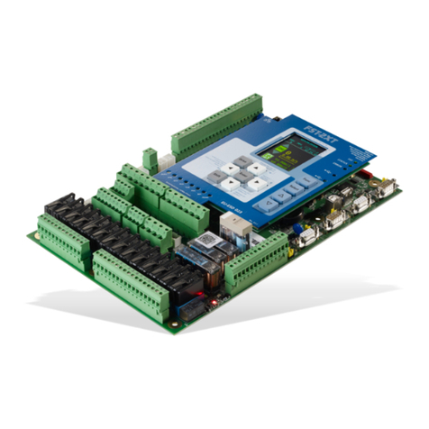
New lift FST-2 User manual

Manual
Field Bus Controller
X7 .2 .
3
.4 .
5
.
6
X
8
.2 .
3
.4 .
5
.
6
X
9
.2 .
3
.4 .
5
.
6
9
.
8
7
.
6
5
.
4
.
3
.
2
6
X
5
.
4
.
3
2
5
X
4
.
3
2
4
X
6
5
.
4
3
2
.
3
X
6
.
5
.
4
3
.
2
.
2
X
9
8
7
6
.
5
.
4
.
3
.
2
.
1
X
5
.
4
3
.
2
.
1
1
X
4
.
3
.
2
.
5
1
X
6
.
5
.
4
3
.
2
.
4
1
X
9
.
8
.
7
.
6
.
5
.
4
3
.
2
.
0
1
X
4
.
3
2
3
1
X
4
.
3
2
7
1
X
4
.
3
2
6
1
X
X19
.
2
.
3
.
4
.
5
.
6
.
7
.
8
X18
.
2
.
3
.
4 .
X2
0
.2 .
3
.4
.
T
1
1
12
13
14
15
16
17
18
19
20
1
2
3
4 5
6
7
8
9
1
0
1
1
12
13
14
15
16
17
18
19
20
1
2
3
4
5
6
7
7
8
8
9
1
0
1
1
12
13
14
15
16
17
18
19
20
1
2
3
4
5
6
7
8
9
1
0
T
GESCHLO
S
SEN
>A< ###@###-
01 14:03:02
D
42.32.22.12.02.91.81.71.61.51.41.31.21.11.01.9.8.7.6.5.4.3.2.1X
X20.2 .3 .4 .5 .6 .7 .8 .9 .10 X21.2 .3 .4 .5 .6 .7 X22.2 .3 .4 .5 .6
21.11.01.9.8.7.6.5.4.3.2.31X
SKZU SPB SPA TKA TKB TKC NHLT FKNHLT
2.4X
H
N
K
F
H
N
C
K
T
B
K
T
A
K
T
A
P
S
B
P
S
U
Z
K
S
Rev. D2.2b
A1
0036
AEB-004
B
C
A
Speicherkarte / memory-card
FST
STATUS
ERROR
Modem
(RS-232)
X10
D
151353791111719
Oberster Ruf / top call
[ oneup ]einsauf /
Unterster Ruf / bottom call
[einsab/ ]one down
[]
Umschalttaste /
shift
Antrieb /
drive
Testmenü / test menu
[]Anzeige rechts / display right
Außensteuerung Aus /
landing calls off
[display left ]
Anzeige links /
24
23
22
21
20
19
18
17
16
15
14
13
12
11
10
9
8
7
6
5
4
3
1
X12
Drehgeber /
encoder
X5
X6
X4
X3
X2
HHT
BUS
Schacht-BUS Einspeisung /
shaft or group-bus power input
Option
BUS
Service
(RS-232)
X9
Antrieb /
drive
X11
X8
Menü, Eingabe / menu, enter
[]Infoanzeige / info screen
X1
Sicherheitskreis / safety circuit
Schach t BUS /
shaft bus

FST-2_HB.EN12/05
Publisher NEW LIFT Steuerungsbau GmbH
Lochhamer Schlag 8
D-82166 Gräfelfing
Phone: +49 (0) 89 / 89 866 - 0
Fax: +49 (0) 89 / 89 866 - 300
Doc. No. FST-2_HB.EN12/05
Date of issue 12/05
Software version V1.100-0350
Copyright © 2005, NEW LIFT Steuerungsbau GmbH
All rights including those of copying and reproduction of parts of this
description and of the translation are reserved by the publisher.
No part of this description may be reproduced in any form or copied with an
electronic replication system without the written permission of the
publisher.

Table of contents
FST-2_HB.EN12/05 1
1 About this manual ..............................................................................................5
1.1 General........................................................................................................................... 5
1.2 Signs and Symbols used ....................................................................................... 5
1.3 Further information................................................................................................... 6
2 General Safety Regulations .........................................................................7
2.1 Standards and regulations applied.................................................................... 7
2.2 Electromagnetic compatibility (EMC)................................................................ 8
2.3 Handling electronic components........................................................................ 8
3 FST-2-Controller user interface ................................................................9
3.1 LC-Display and messages................................................................................... 10
Main screen..................................................................................................................... 10
Line A .............................................................................................................................. 10
Line B .............................................................................................................................. 11
Line C.............................................................................................................................. 13
Line D.............................................................................................................................. 27
Information texts.............................................................................................................. 28
Information page.............................................................................................................. 31
3.2 Keypad functions................................................................................................... 32
Frequency converter with DCP interface......................................................................... 32
When switching on .......................................................................................................... 32
Main screen..................................................................................................................... 33
Main menu and test menu............................................................................................... 33
Error list........................................................................................................................... 34
Information page.............................................................................................................. 34
3.3 LEDs.............................................................................................................................. 34
4 Technical data ..................................................................................................... 35
4.1 Component overview – bus plan ...................................................................... 36
4.2 FST-2-Controller....................................................................................................... 37

Table of contents
2FST-2_HB.EN12/05
Safety Monitoring Device................................................................................................. 44
4.3 FSM car control module........................................................................................ 53
4.4 FPM car panel module........................................................................................... 65
4.5 FPE car panel extension module..................................................................... 72
4.6 FPA car control panel adapter........................................................................... 77
4.7 ADM landing call module ..................................................................................... 81
4.8 RIO-ADM remote I/O module............................................................................... 84
4.9 RIO-FPM remote I/O module ............................................................................... 87
4.10 LON bus....................................................................................................................... 91
4.11 Trailing ribbon cable.............................................................................................. 92
5 Menu tree .................................................................................................................95
5.1 General......................................................................................................................... 95
5.2 MAIN MENU – Service.......................................................................................... 104
5.3 MAIN MENU – Drive.............................................................................................. 106
5.4 MAIN MENU – Config........................................................................................... 111
5.5 MAIN MENU – Positioning.................................................................................. 127
5.6 MAIN MENUE – Calls............................................................................................ 134
5.7 MAIN MENUE – System....................................................................................... 136
5.8 MAIN MENUE – Doors.......................................................................................... 139
5.9 MAIN MENU.............................................................................................................. 144
5.10 TEST MENU.............................................................................................................. 145
6 Programmable inputs and outputs ....................................................147

Table of contents
FST-2_HB.EN12/05 3
General.......................................................................................................................... 147
Programming................................................................................................................. 148
Setting the RAW register............................................................................................... 148
Function “landing call” ................................................................................................... 153
Function “fire signal”...................................................................................................... 154
Function “priority landing”.............................................................................................. 155
Function “position indicator” .......................................................................................... 156
Function “flag”................................................................................................................ 157
User error ...................................................................................................................... 161
Function “signal”............................................................................................................ 162
Function “evacuation”.................................................................................................... 164
Function “special drive” ................................................................................................. 166
Function “alarm misuse”................................................................................................ 167
Function “speed threshold”............................................................................................ 168
Function “ramp drive” .................................................................................................... 169
Function “override floor blocking”.................................................................................. 170
Function “block floors”................................................................................................... 171
7 Error List ................................................................................................................173
7.1 LC-Display................................................................................................................ 173
7.2 Keypad functions.................................................................................................. 173
7.3 Event messages..................................................................................................... 174
7.4 Error messages...................................................................................................... 175
8Index.........................................................................................................................181

Table of contents
4FST-2_HB.EN12/05

1 About this manual
1.1 General
FST-2_HB.EN12/05 5
1 About this manual
1.1 General
The FST-2 manual is a comprehensive reference work for experienced lift
service experts.
Goals of this manual
- describe the characteristics of the LON bus technology
- describe technical details and functions of the FST-2 and its
components
- describe the operation of the FST-2
- describe the configuration of the FST-2
- describe the FST-2 menu and its settings
- describe the messages of the FST-2
1.2 Signs and Symbols used
Below you can find a description of the signs and symbols used in this
manual.
Symbols +Key combination:
Press the linked keys simultaneously.
³
Action:
Actions are executed immediately and will not be saved as permanent
settings.

1 About this manual
1.3 Further information
6FST-2_HB.EN12/05
LC-Display and keypad In the left column you will find the LC-Display of the FST-2-Controller with
a grey background. The displays and messages or possible keypad
functions are explained in the table.
1.3 Further information
The following documentation is available for the FST-2-Controller and its
components:
- Description of FST-2-Controller
- FST-2 Installation & Commissioning
- FST-2 Quick Guide
- FST-2 Manual (this document)
- GST Manual
- System description – pawl Device
- Installation & Commissioning – FAX Modem
- Quick Guide EAZ-256
- Quick Guide EAZ-VFD
- Quick Guide EAZ-LCD
- Quick Guide FST-2-IRT
- Manual for Fireman Mode
- System description – Speech Output
- System description – Attika Control
- System description – Bank-Control
- System description – Ramp-Drive
- System description – Panel Test
- System description – Safety curtain
NEW LIFT is happy to provide this documentation on request. Please
contact our marketing department.
Line or
key Description of display or keypad functions
LC-Display

2 General Safety Regulations
2.1 Standards and regulations applied
FST-2_HB.EN12/05 7
2 General Safety Regulations
The FST-2-Controller must be in technically perfect condition and may only
be used in accordance with regulations and in awareness of safety and
risks. The “FST-2 Installation & Commissioning” manual as well as the
relevant guidelines for the prevention of accidents and the guidelines of
local power utilities must be observed.
2.1 Standards and regulations applied
The FST-2-Controller complies with:
- Regulation for lift systems
(German regulation for lift systems, AufzV)
- Safety regulations for the construction and installation of passenger
lifts, building hoists and service lifts (DIN EN 81 Parts 1 and 2)
- Technical regulations for lifts (TRA, Technische Regeln für Aufzüge)
Operation of lift systems (TRA 007)
Testing parts and components (TRA 101)
Passenger lifts, building hoists and service lifts (TRA 200)
- Regulations for the erection of power installations with rated voltages of
up to 1kV (DIN VDE 0100)
- Measures for contact voltage protection in the engine room (DIN EN
60990)
- Data sheet on safety measures during installation, maintenance and
servicing or repair of lift systems (ZH 1/312)

2 General Safety Regulations
2.2 Electromagnetic compatibility (EMC)
8FST-2_HB.EN12/05
2.2 Electromagnetic compatibility (EMC)
An accredited inspection body has verified that the FST-2-Controller and
its components comply with the standards, limits and test intensities
according to EN 12015/1995 and EN 12016/1995.
The FST-2-Controller and its components are:
- resistant against electrostatic discharges
(EN 61000-4-2/1995)
- resistant against electrostatic fields
(EN 61000-4-3/1997)
- resistant against transient disturbances
(EN 61000-4-4/1995)
The field strengths of electromagnetic disturbances radiated by the FST-2-
Controller and its components do not exceed the permitted limits.
(EN 55011/1997)
2.3 Handling electronic components
Leave electronic components in their original packaging until installation.
Touch a grounded piece of metal prior to opening the original packaging to
prevent damage from static charges.
All bus inputs and outputs not in use must be equipped with a terminal
resistance (terminator).

3 FST-2-Controller user interface
FST-2_HB.EN12/05 9
3 FST-2-Controller user interface
The user interface of the FST-2-Controller is located on the FST-2 main
circuit board in the control cabinet of the lift system. The FST-2 user
interface consists of front panel, LC-Display, keypad and LEDs.
Fig. 3.1 FST-2-Controller user interface
SAFETY CCT CLOSED

3 FST-2-Controller user interface
3.1 LC-Display and messages
10 FST-2_HB.EN12/05
3.1 LC-Display and messages
The LC-Display consists of four lines A, B, C and D with 20 digits each.
After switching on and during normal operation, the FST-2-Controller
displays the main screen.
Main screen
Line C has a special status. In normal mode (after switching on), it displays
status messages (see “Status messages in line C” on page 13). When
switching with key combination
S
+
¥
+
¤
it displays diagnostic
messages, see “Diagnostic messages in line C” on page 14.
Also see “Keypad functions” on page 32.
Line A
Safety circuit messages
in Line A
A Maximum active state of the safety circuit
B Active state or error
C Status of the lift system / diagnostic message
D Data for current drive mode
SAFETY CCT CLOSED
>AX< ###@###
00 13:06:56
Display Description
SAFETY CCT CLOSED
The safety circuit is completely closed
(FST X14.1 & FST X14.2).
SFTY-CLOSED MISSING
The input “Safety circuit closed”has no power.
Possible reasons:
-Terminal FST X14.1 has no power (normally
bridged with X14.2)
-Relay K14 on the FST is faulty
DOOR LOCK B OPEN
The shaft door contact of door side B is
interrupted (FST X14.2 and X14.3).
DOOR LOCK A OPEN
The shaft door contact of door side A is
interrupted (FST X14.3 and X14.4).
DOOR A OPEN
The car door contact of door side A is
interrupted (FST X14.4 and X14.5).
DOOR B OPEN
The car door contact of door side B is
interrupted (FST X14.5 and X14.6).
DOOR C OPEN
The car door contact of door side C is
interrupted (FST X14.6 and X14.7).
MANUAL DOOR OPEN
A manual door contact is interrupted
(FST X14.6 and X14.7).
EMERGENCY END
SWITCH
The top emergency end switch of an hydraulic
lift is interrupted (FST X14.6 and X14.7).

3 FST-2-Controller user interface
3.1 LC-Display and messages
FST-2_HB.EN12/05 11
The messages
DOOR C OPEN
,
MANUAL DOOR OPEN
and
EMERGENCY
END SWITCH
are triggered by the same safety circuit input of the FST-2
(TC input: FST-2 X14.6) and exclude each other.
Line B
State messages in line B
EMERGENCY STOP
An emergency switch in the shaft is interrupted
(terminals FST X14.7 and X14.8).
EMERGENCY STOP-CAR
An emergency switch on the car is interrupted
(terminal FST X32.4).
Display Description
Display Description
24V LOW!
The 24V supply of the FST-2 board (FST X1.1
and X1.2) is below the permitted range of 24V -
10%. Check power supply and wiring.
LANDING CALLS OFF
Landing control is blocked by a safety circuit
interruption (interruption before terminal FST
X32.4), line A displays
EMERGENCY STOP
,
see “
EMERGENCY STOP
” on page 11.
LANDING CONTROL OFF
Landing control was switched off manually.
Possible sources:
-
¥
key of the FST-2 keypad
-Programmable input of an external RIO
module
-Input FST X1.14
-Programmable input of the FST-2-Controller
-Key switch on car panel (FPM input X4.34)
-Key switch on landing panel (ADM input
X3.12 / X3.13)
FIREMAN
A fire input is active. Possible reasons:
-Fire input on landing call module (ADM input
X3.12 / X3.13)
-Programmable input of the FST-2-Controller
-GST Group Controller (see GST Manual)
END-SWITCH TEST
The manual end switch test is running, see test
menu.
ES-SPEED MON. TEST
The manual test of the deceleration monitoring
function at the top and bottom limits is running,
see test menu.
EVACUATION
The controller is in evacuation mode. Possible
sources for the evacuation signal:
-Programmable input of the FST-2-Controller
-Programmable input of the GST Group
Controller
-LMS over PAM protocol adapter module
SEND FAX
The controller is in fax mode (see Installation &
Commissioning – Fax modem).

3 FST-2-Controller user interface
3.1 LC-Display and messages
12 FST-2_HB.EN12/05
LIFT OFF
The controller was shut down. Possible
sources:
-Car light failure
-Input “Car Light OFF”, FST X1.13
-Programmable input/output of an external
RIO module
-Programmable input/output of the FST-2-
Controller
-Externallyby theGST Group Controllerorthe
LMS Lift Monitoring System
FIREMAN MODE
Fireman mode is activated. Possible sources:
-Key switch on car panel (FPM X4.4)
-Programmable input/output of the FST-2-
Controller
-The state was saved after a powerfailureand
hasbeenreconstructed.Function
Fireman
Mode Reset
must be used to reset this
state.
-Key switch on landing panel (ADM input
X3.12 / X3.13)
-GST Group Controller (see GST Manual)
FILE TRANSFER
ACTIVE
The controller is in remote data transmission
mode to transfer files to a GST Group
Controller or to a PC.
INSPECTION
The controller is in inspection mode (input FSM
X22.2).
Attention: Line A of the FST-2 display must
show
EMERGENCY STOP-CAR
!
CALIBRATION -
A calibration drive was started. The number of
remaining runs is displayed.
APRON-OPEN!
The hinged car apron is open (due to a shaft
door interruption). Monitoring is done via a
programmable input of the FST-2-Controller.
LEARN DRIVE ACTIVE
The controller performs a learn drive.
LEARN DRIVE-START
The controller performs a learn drive.
LEARN DRIV-OK!
Learn drive completed successfully.
LEARN DRIVE-ABORT
The learn drive was cancelled due to a fault.
The reason is entered in the error list.
SAFETY CURTAIN
The safety curtain replacing the car door was
interrupted. The contact is in the safety circuit
instead of the car door contacts (see System
description – Safety curtain).
DRM ..
A runtime monitoring error has occurred. There
are different types of runtime monitoring
functions that can shut down the lift.
INSTALLATION MODE
The controller is in installation mode.
ORIENTATION
The controller performs an orientation drive to
the top or bottom limit after switching on (only
when using INK – incrementalpositioning). The
orientationdrivecan takeplaceautomaticallyor
when the first call is placed.
Display Description

3 FST-2-Controller user interface
3.1 LC-Display and messages
FST-2_HB.EN12/05 13
Line C
Status messages in line C Line C is divided and displays one of the following status messages in the
left and in the right part. For scrolling the status messages in the left part
use the key combination
S
+
¤
, for the right part use the key combination
S
+
¥
.
The door positions marked with
A
also apply to doors
B
and
C
.
PARK DRIVE ACTIVE
The controller sends the car to a programmed
parking floor.
PRIORITY LANDING
A priority landing drive was triggered. Possible
sources:
-Key switch on landing panel (ADM input
X3.12 / X3.13)
-Programmable input of the FST-2-Controller
-Programmable input of an external RIO
module
PRIORITY CAR
A priority car drive was triggered. Possible
sources:
-Key switch on car panel (FPM input X4.37)
-Automatically after a type Auto 2 priority
landing drive.
AUXILIARY
The controller is in auxiliary mode (input FST
X18.2).
Attention: Line A of the FST-2 display must
show
EMERGENCY STOP
!
HOMING ACTIVE
The hydraulic lift is sent to the lowest landing.
SERVICE ACTIVE
The controller is in service mode, see test
menu.
SERVICE REQUIRED!
Oneof the service counters has exceededa set
limit.
SYSTEM STOP
The controller was stopped via the FST-2
menu.
OVERLOAD
The overload input on the FSM or on a
programmable input is active.
USER ERROR -
A user error has occurred. The number of the
error is displayed.
VIP MODE
The controlleris in VIP mode. Possible sources
VIP mode:
-LMS over PAM protocol adapter module
-Programmable input of the FST-2-Controller
-FPM input X4.34 on car panel
FULL LOAD
The full load input of the FSM is active.
Display Description

3 FST-2-Controller user interface
3.1 LC-Display and messages
14 FST-2_HB.EN12/05
Diagnostic messages in line C Line C canbe switched from status messages to diagnostic messages with
key combination
S
+
¥
+
¤
. Use key combinations
S
+
¥
and
S
+
¤
to
scroll through the diagnostic messages.
Status Display Description
Car doors
<A>
Door A completely open
>A<
Door A closed
<-A->
Door A is opening
->A<-
Door A is closing
<A*>
PhotocellorreversingcontactdoorA
active
<AX>
Door A is locked (test menu)
<AL>
Door is in loading mode (loading
button activated)
-A-
Door A is stopped
?A?
State of door A is unknown (check
door limit switches)
<-<>->
Door open button active
->><<-
Door close button active
Shaft positioning
Z
Zone message active
F
Zone message missing
-
Car is in levelled position
###@###
Car position relative to levelled
position (each pixel = 2.5 mm)
ö
Correction switch bottom KU active
ä
Correction switch top KO active
Car position
P=6200
Current position of the car relative to
levelled position of lowest landing in
[mm]
Levelling
Pd= -2
Current position of the car relative to
closest levelled position in [mm]
Car speed
V=1300
Current speed of the car in [mm/s]
Set / actual speed
@######V2
Comparison between setand actual
speed of the car. The left bar is a
graphic display of the relation
between actual speed and the set
speed on the right.
Motor hours
BS=4351
Operating hours of the drive
Drive counter
FZ=123456
Number of completed drives
Memory occupied
Rec: 45%
Memory occupied on the PC-Card
when recording

3 FST-2-Controller user interface
3.1 LC-Display and messages
FST-2_HB.EN12/05 15
Display Description
LIK-Errs:00000 00000
Diagnosis of absolute value encoder
function (see page 16), this display is
irrelevant when using incremental
positioning.
ENC:10000000[989680]
Real-time display of increments counted by
the encoder on plug X2. The counted
increments together with the covered
distance can help when calculating the
required
Resolution
.
Gray=43210 KO KU ZB
Current state of the solenoid switches with
incremental positioning, see page 16
Door-A: F1=00 F2=00
Current state of the FSM for door A, see
page 16
Door-B: F1=00 F2=00
Current state of the FSM for door B, see
page 16
Door-C: F1=00 F2=00
Current state of the FSM for door C, see
page 16
Motor=00 VST=0000
Internal motor state (see page 19) and
states of the pre-selection contact outputs
(see page 20)
Pos:Virt=0b Real=00
Generated and actual position messages
from the car, see page 20
SHK=SABCN
State of the safety circuit, see page 22
Mgr1:Drv=00 Call=00
Internal NEW LIFT diagnostic message
Mgr2:A=02 B=00 C=00
Internal NEW LIFT diagnostic message
NextPoss=ff VT=V2
Next possible stop (
NextPoss
) that can
be approached and the setspeed (
VT
), see
page 22
Port EXIN1=EGALPUDR
State of input EXIN1, see page 22
Port EXIO2=76543210
State of input EXIN2, see page 23
Port H8IN1=ZBSMVO
State of input H8IN1, see page 23
FSM-X6: L=1 V=0 K=0
State of outputs on FSM X8 and X19, see
page 23
SRC:00 00 00 00 00
Source of the special drive signals fireman,
fireman mode, landing control OFF, lift off
and service mode, see page 24
LWE: 255% E0 F0 O0
State of the weight sensor, see page 25
Proj.Status=........
State of the project specific parts of the
program (internal)
PC:s0 m1 c0 f0 Mb005
State of the PC-Card slot, see page 26
Pkt\s In=005 Out=002
Incoming and outgoing data packets of the
FST-Controller in [packets/sec]
ASV: 0000000 P=[00]
State of the pawl device, see page 26
FSM msgs=00123
Number of message packets from the FSM
car control module to the FST-2-Controller

3 FST-2-Controller user interface
3.1 LC-Display and messages
16 FST-2_HB.EN12/05
Absolute value encoder
function
LIK-Errs:00000 00000
The two numbers on the display show the number of encoder failures since the last
activation of the system. The left number shows the different values resulting from
double scanning, the right number shows the number of failed plausibility checks.
Sporadic errors are compensated by the FST Software and can be tolerated. A
continuous increase of one of these values indicates an encoder or cable failure.
Left number:
Right number:
State of incremental
positioning
Gray=43210 KO KU ZB
Display Description
00000
or constant value Communication between the FST-2-Controller
and the absolute value encoder is working
correctly. Double scanning to suppress electric
interference does not show any differences.
constantly rising value Double scanning to suppress electric
interference does show differences. There is
electric interference on the connection cable
between FST-2-Controller and encoder.Check
connection cable and inform your NEW LIFT
Hotline.
Display Description
00000
The position values of the absolute value
encoder are plausible (are within the regular
shaft). There are no invalid jumps in the
position value.
RANGE
The position values of the absolute value
encoder are not plausible (are outside the
regular shaft). Check direction of rotation of the
encoder and commission the linear positioning
function, see “Installation and Commissioning
Manual”.
DELTA
There are invalid jumps in the position value.
Absolute value encoder faulty.
Code Description
43210
Stateof Gray-coded pre-limitswitches for high-speed lifts (optional)
KO
Correction switch top (KO) active
KU
Correction switch bottom (Ku) active
ZB
Zone switch B active

3 FST-2-Controller user interface
3.1 LC-Display and messages
FST-2_HB.EN12/05 17
States of the FSM car
control module
Door-A: F1=00 F2=00
State bytes F1 and F2 describe the states of eight functions each in real-
time (8 bits, hexadecimal code). Hexadecimal bytes are coded number by
number. Each number has a decimal value according to the following table:
Fig. 3.2 Hexadecimal encoding of an 8-bit register
Hexadecimal
number Decimal
value
0
0
1
1
2
2
3
3
4
4
5
5
6
6
7
7
8
8
9
9
a
10
b
11
c
12
d
13
e
14
f
15
digit
digit

3 FST-2-Controller user interface
3.1 LC-Display and messages
18 FST-2_HB.EN12/05
Each number codes four functions (bits) of the F1/F2 table with its decimal
value. The decimal value of the number corresponds to the sum of the
values of the activated functions according to the following tables.
* Signal only relevant for door versions A and B.
Example:
State byte F1 = 6c and state byte F2 = 21
This results in the following hexadecimal numbers:
F1:
Number 1 = “c” (decimal = 12)
Number 2 = “6” (decimal = 6)
F2:
Number 1 = “1” (decimal = 1)
Number 2 = “2” (decimal = 2)
The decimal numbers are calculated from the following values:
F1:
Number 1 = 12 = 8 + 4
Bit Number Value Setting
F1 =
Byte F1
0Number 1
(right number)
1 active FSM car control module configured
1 2 active Door locked
2 4 active Door reversing
38Doorcompletely
open Limit switch “door open”
4Number 2
(left number)
1Doorcompletely
closed Limit switch “door closed”
5 2 active Photocell interrupted
6 4 active Reversing contact
7 8 active Minimum load input*
Bit Number Value Setting
F2 =
Byte F2
0Number 1
(right number)
1 on Car light sensor*
1 2 active Inspection signal “fast”
2 4 active Inspection signal “down”
3 8 active Inspection signal “up”
4Number 2
(left number)
1 active Inspection signal “ON”
5 2 active Door closing motor
6 4 active Door opening motor
7 8 active Door ready for drive
SAFETY CCT CLOSED
Door-A: F1=6c F2=21
00 13:06:
Table of contents
Other New lift Controllers manuals
Popular Controllers manuals by other brands
Loctite
Loctite Single CureJet Operation manual
Emerson
Emerson Fisher 133H installation guide

Dometic
Dometic 9600023541 Installation and operating manual
DEMA
DEMA Olympian O-RDV manual
Johnson Controls
Johnson Controls M9206-DN Series installation instructions
Rockwell Automation
Rockwell Automation Allen-Bradley AADvance T9110 Solutions handbook
IBM
IBM Netfinity ServeRAID-4L Ultra160 User reference
Johnson Controls
Johnson Controls ATC1510 installation guide

SAH
SAH WSK Series user manual
QuietCool
QuietCool IT-AF-SMT owner's manual
Easyrain
Easyrain Rain Bird ESP-TM Series Installation, Programming, & Operation

Watlow Electric
Watlow Electric F4S Series user manual
