Clarke CAR8MC User manual

USER GUIDE
Models CAR8MC & CAR15MC
PART NOs: 3126105 & 3126100
gc01/09
Retractable Air Hose Reel

2
INTRODUCTION
Thank you for purchasing this CLARKE Air Hose Reel.
Please read this manual thoroughly and follow the instructions carefully. Before attempting to use
the hose reel, thoroughly familiarise yourself with the reel & its operation. In doing so you will
ensure the safety of yourself and that of others around you, and you can look forward to the hose
reel giving you long and satisfactory service.
GUARANTEE
This product is guaranteed against faulty manufacture for a period of 12 months from the date of
purchase. Please keep your receipt which will be required as proof of purchase.
This guarantee is invalid if the product is found to have been abused or tampered with in any
way, or not used for the purpose for which it was intended.
Faulty goods should be returned to their place of purchase, no product can be returned to us
without prior permission.
This guarantee does not effect your statutory rights.
Please note: seals, plastic rollers and rubber stopper are considered to be
consumable spares and as such are not covered by this warranty.
PARTS & SERVICE
ENVIRONMENTAL PROTECTION
Do not dispose of this product with general household waste. It should be
disposed of at a recognised disposal facility and in accordance with local
authority guidelines.
For spare parts and service, please contact your nearest dealer, or CLARKE International, on one
of the following numbers:
PARTS & SERVICE TEL: 020 8988 7400 / FAX: 020 8558 3622
or e-mail as follows:
PARTS: [email protected]
SERVICE: [email protected]

3
GENERAL SAFETY RULES
1. NEVER exceed the rated operating pressure for this device - 20bar (300psi).
2. NEVER allow the hose to retract freely. It should always be restrained to prevent the air tool
from whipping, with resultant damage to persons or property.
3. NEVER allow children to use the hose reel. Keep children clear of the work area at all times.
4. ALWAYS check for damage before using the hose. Any damage should be properly repaired
or the part replaced. Consult your local dealer.
5. ALWAYS ensure trailing hose does not constitute a trip hazard.
6. ALWAYS wear eye protection when assembling and using the hose reel.
7. ALWAYS take precautions with respect to the use of compressed air.
Remember....compressed air is hazardous.
8. ALWAYS ensure all air connections are properly sealed using teflon tape or pipe sealant.
SPECIFICATION
This CLARKE retractable air hose reel incorporates a spring driven, automatic rewind with locking
ratchet mechanism (eight locking positions per revolution).
Models: ...................................................................... CAR8MC & CAR15MC
Part Nos: .......................................................................... 3126105 & 3126100
Air Hose Size ......................... 8 metres (CAR8MC), 15 metres (CAR15MC)
Reel Air Inlet (F) ................................................................................. 1/4” BSP
Reel Air Outlet (M) ............................................................................ 1/4” BSP
Maximum Pressure: ............................................................... 20 Bar (300 PSI)
Maximum Air Flow: ............................................................................. 25 CFM
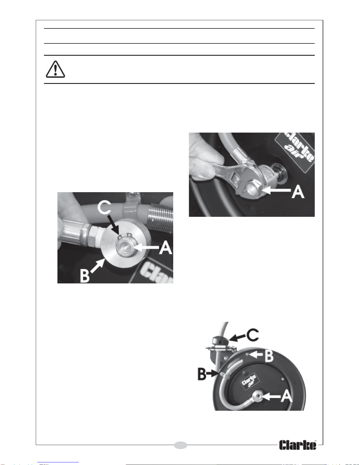
INSTALLATION
The hose reel may be mounted to a wall, floor or ceiling as required. Ensure the mounting
hardware (not supplied) and the mounting position is of sufficient strength to support the hose
and reel, plus the force required to extend the hose.
1. Choose a suitable mounting position close enough to the compressor that the two items can
be connected together using a shorter length of hose and from where, the air compressor
can be conveniently adjusted.
2. Mount the reel using four 1/2” bolts with washers secured through slots in the mounting
base.
The position of the hose guide bracket, (containing the roller supports), may be changed
depending upon the mounting position as illustrated on the following page.

4
To change the position of the guide arm, proceed as follows:
1. Pull out the hose a short distance and allow it to ‘latch’.
2. Remove the 4 nuts securing the arm and roller bracket to the hub, noting that the bolts used
are ‘coach bolts’.
3. Move the arm with roller bracket in 90deg increments to the chosen position, as required,
and reassemble to the hub.
NOTE: This may be a little tricky if the coach bolts fall out. By inserting one bolt and
securing with a washer and nut first, then turning the drum whilst inserting the remaining
bolts, will simplify the operation.
4. When the reel is secured in postion, attach the air hose coming from the compressor.
5. Wrap the threads of the male connector with teflon tape (supplied), or other thread sealant,
and connect to the air inlet valve on the side of the hose reel. Connect the other end of the
incoming air hose to the compressor. Use teflon tape to hose outlet when attaching air
powered tools.
6. If required, adjust the hose stopper which determines the length of hose that remains
outside the reel. To adjust, pull hose out past the desired position of the hose stopper and
latch the reel. Loosen both stopper bolts and move stopper to chosen position before re-
tightening bolts.
OPERATION
1. Check the reel for correct operation, as follows:
2. Gently pull out the hose - a series of clicks will be heard, every half revolution of the drum.
3. When a click is heard, release the hose. It should be held by the latch. Continue to pull out
the hose, and after a series of clicks, at various lengths, release it to check the operation of
the latch.
4. To release the latch, give the hose a brief tug, and allow the hose to retract, under control,
until the stopper rests on the hose guide. Do not let go of the hose.
5. Periodically, check the hose for excessive wear and hose connections for leaks.

5
MAINTENANCE
WARNING: Before carrying out any maintenance tasks always be sure
to turn off the air supply to the Hose Reel and release any pressure in
the airline.
Periodically, check the hose for wear and damage, and the swivel fitting for leakage using
soapy water. Any damage or leaks should be repaired before further use. Swivel seal and hose
replacement tasks are carried out as follows:
A Inlet Swivel Seal (O-ring) replacement
1. Disconnect incoming air supply and the air
inlet hose from the brass inlet air valve.
2. Undo and remove the inlet air valve
assembly from the shaft by fitting a wrench
onto the hexagonal portion of valve and
turning counter-clockwise.
3. Remove the retaining ring and slide
the air inlet valve swivel collar from the air inlet
valve body.
4. Remove warn/damaged O-rings (2 pcs)
and replace with new parts.
5. Re-assemble in reverse order.
B Replacing the hose
1. Secure and stabilise the reel. It should be possible to replace the hose with the reel still
mounted in position.
2. Disconnect the incoming air supply.
3. Pull out the entire length of the hose and lock
the reel. Ensure it is securely locked in place.
4. Unscrew the hose clamps ‘B’ that attach the
hose to the drum. Disconnect inlet end of the
hose from the air inlet valve ’A’.
5. Pull the inlet end of the hose through the slot
in the drum and guide rollers, removing the old
hose completely.
6. Remove the spring hose guard, hose clamp
and hose stopper ‘C‘ from old hose. Fit these
parts onto the new hose in identical positions.

6
7. Feed the inlet end of the hose through the guide rollers and the slot in the drum.
8. Apply some teflon sealing tape or thread sealant to the hose connector and connect the air
inlet valve.
9. Attach the hose clamp to the drum and rewind the hose onto the reel using normal
operation.
C Hose Recoil Tension Adjustment
1. Disconnect incoming air supply.
2. Pull out about 2 feet of hose and latch the reel.
3. Remove hose stopper (part 28).
4. Firmly hold the edge of the reel drum and unlatch the reel. carfully allow drum to slowly
rewind, drawing the hose end back through the guide arm roller assembly and onto the reel.
Latch the reel in position.
5To increase tension: Unlatch reel and turn clockwise (as viewed from the air inlet side).
To decrease tension: Unlatch and allow reel to rotate anti-clockwise (as viewed from the air
inlet side).
6. Once the desired spring tension is reached, latch reel in position. Feed hose end through
the roller assembly in guide arm and re-attach hose stopper.
7. Re-connect incoming air supply.
D Replacing the Spring Canister
1. Follow steps 1-4 under Recoil Tension Adjustment above.
2. Unlatch the reel and allow the drum to slowly rewind until the tension in the spring is relieved
and the reel stops. Carefully control the speed of the drum and do not release while re-
winding.
3. Remove the air inlet valve and spacing washer. Refer to A. Replacing the Air Inlet Valve O-
rings: step 2.
4. Remove nuts from mounting bracket side of drum inside drum cavity. Do not attampt to
remove spring canister nuts on air inlet side of drum.
5. Pull entire spring canister (1) off the drum axle (13). Replace with a new spring canister.
6. Reverse the above procedure to re-assemble.
7. After assembly, re-tension the reel by turning the drum three complete turns clockwise (as
viewed from air inlet side) and latch the reel.
8. Feed the hose through the guide arm and re-attach the hose stopper.
IMPORTANT! If the rewind spring fails for any reason, it is strongly recommended
that, for safety reasons, it is replaced by a trained technician, or returned to your
Clarke dealer for repair.

7
PARTS DIAGRAM
No. Description Part No.
1 Spring Canister CAR8MC01
2 Hose Drum-Inner CAR8MC02
3 Hose Drum-Outer CAR8MC03
4 Base Mtg Bracket CAR8MC04
5 Guide Arm CAR8MC05
6a Air Inlet Valve Body CAR8MC6A
6b Air inlet Swivel Collar CAR8MC6B
7 Hose CAR8MC07
8 Spring Hose Guard CAR8MC08
9 Hub Bearing Assembly CAR8MC09
10 Bolt CAR8MC10
11 Locking Cam CAR8MC11
12 Spring CAR8MC12
13 Axle CAR8MC13
14 Lock Washer CAR8MC14
15 Nut CAR8MC15
16 Bolt CAR8MC16
17 Nut CAR8MC17
18 Clamp CAR8MC18
19 Clamp CAR8MC19
No Description Part No.
20. Bolt CAR8MC20
21. Washer CAR8MC21
22. Nut CAR8MC22
23. Washer CAR8MC23
24. Bolt CAR8MC24
25. Nut CAR8MC25
26. Lock Nut CAR8MC26
27. Roller Guide Bracket CAR8MC27
28. Rubber Stop Block CAR8MC28
29. Ratchet Locking Gear CAR8MC29
30. Spacing Washer CAR8MC30
31. Retaining Ring CAR8MC31
32. Bolt CAR8MC32
33. Lock Washer CAR8MC33
34. Setscrew CAR8MC34
35. Spacing Washer CAR8MC35
36. Nut CAR8MC36
37. Spacing washer CAR8MC37
38. Pin CAR8MC38

This manual suits for next models
3
Table of contents
Other Clarke Other manuals
Popular Other manuals by other brands

GO Industries
GO Industries 38017 installation instructions

Sunex HD
Sunex HD 6744 owner's manual

Westin
Westin 40-1095 instructions

American Bath Factory
American Bath Factory Sistine Stone Neo Corner-Hnf installation guide

Sissel
Sissel HEATING PILLOW Instructions for use

Altec Lansing
Altec Lansing INMOTION COMPACT brochure