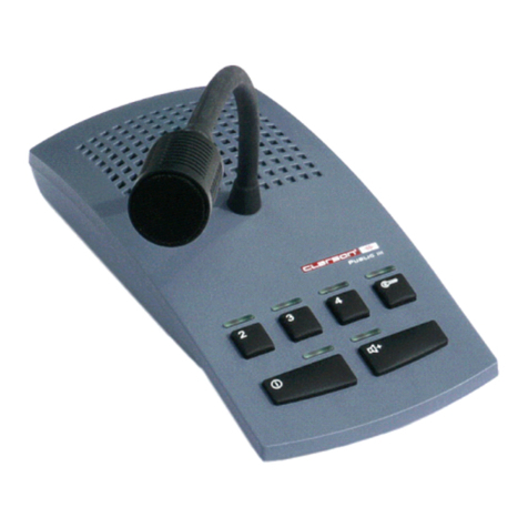
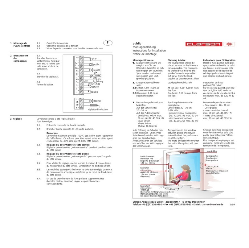
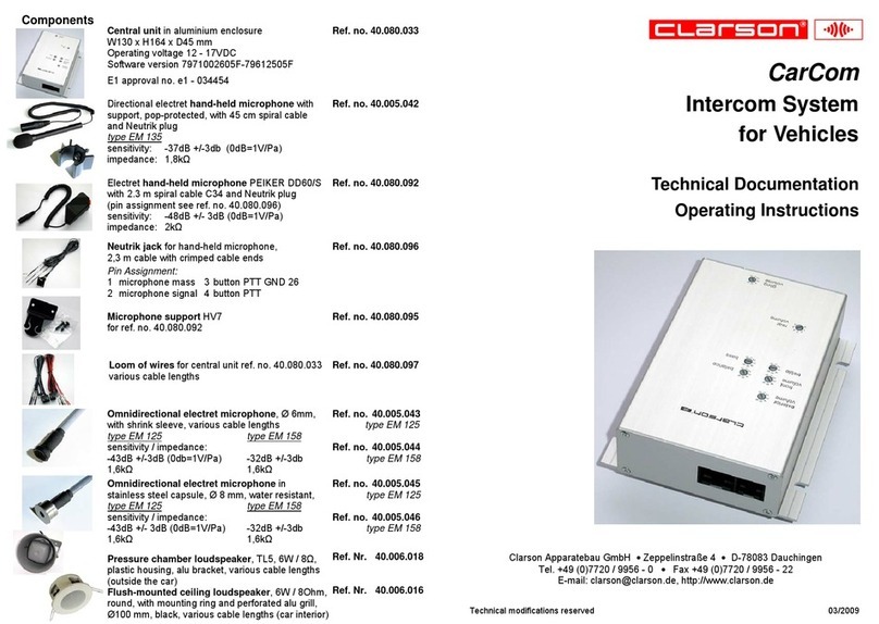
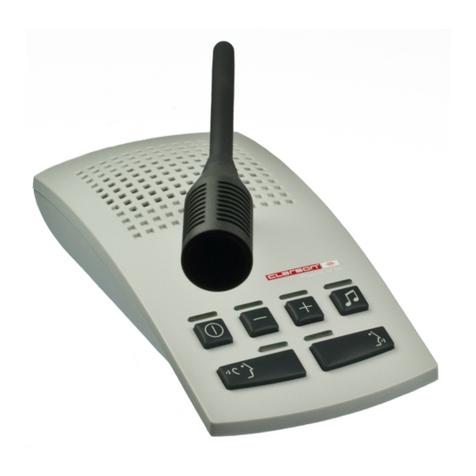
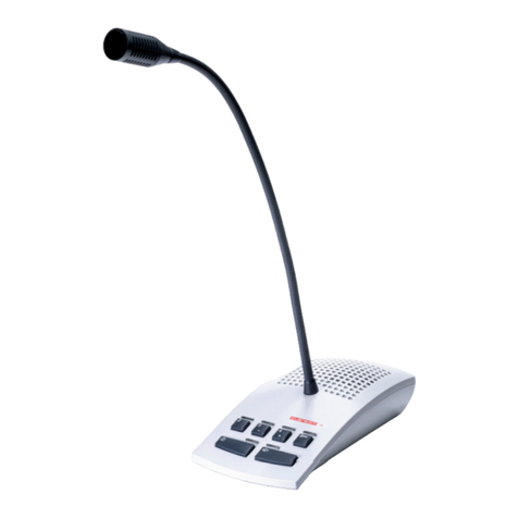
Clarson PUBLIC III CE User manual

PUBLIC III CE
Intercom System Comfort Edion
Service and Installaon Instrucons
Key funcons, LED signals.........................................................................................................................10
PTT mode..................................................................................................................................................10
Service sengs .........................................................................................................................................11
Volume control .........................................................................................................................................11
External connecons for headset, audio player, audio recorder..............................................................11
Installaon instrucons .......................................................................................................................... 4/5
Installaon intercom .............................................................................................................................. 6/7
Installaon intercom with footswitch..................................................................................................... 8/9
Installaon microphone ......................................................................................................................... 7/9
Installaon loudspeaker ......................................................................................................................... 7/9
Open duplex
Push-to-talk
Headset interface
Speech key control via footswitch
Music input
Recording possibility
AEC (Automac echo cancellaon)
NR (Noise reducon)
NG (Noise gate)
Individual volume control for loudspeaker / microphone/ headset /
audio via +/- keys
Balanced microphone inputs
Voltage/power...................................................................................................................... 15VDC/700mA
Maximum power consumpon (limited by power supply)................................................................. <15W
Power consumpon in OFF-mode ................................................................................................... <0.15W
Maximum output impedance (no connuous operaon) at 8Ω/channel............................................... 5W
Minimum loudspeaker impedance .......................................................................................................... 8Ω
Audio IN-input level/input impedance ..........................................................................max. 100mV(1)/2kΩ
REC OUT-output level/output impedance .............................................................................max.3V(2)/2kΩ
Temperature :............................................................................................................................... 10 - 40 °C
Humidity: .................................................................................................... 20 % to 75 % (non condensing)
Air pressure:.................................................................................................................700 hPa to 1060 hPa
(1)Connect Audio IN to the headphone jack of the audio source.
Tune output level of the audio source in such a way that in case of maximum volume overmodulaon of the intercom system
is avoided.
(2)This value depends on the volume set, on the speech volume and on the distance to the microphone. 35.054.012 07/2015
Table of Contents
Features
Technical Data

23
~
40.005.171
Omnidireconal microphone EM 158 in ABS housing
colour RAL 9010, label 32.054.007, 1 m cable with RJ45
plug 40.054.470, label 32.054.046, wall/ceiling holder
40.005.094, cover plate 06.054.06
40.054.811
Central unit
colour RAL 9010 (40.054.453)
Labels 32.054.013 and 32.054.014
Power cable EU, 2m , labels 32.054.032/033 40.054.834
Power cable USA, 2m, labels 32.054.132/133 40.054.835
Power cable UK, 2m, labels 32.054.232/233 40.054.836
Surface mounted loudspeaker 6W / 20Ω
colour RAL 9010, label 32.054.005
cable outlet top/boom (40.006.174)
40.006.173
Power supply GPP10 Medical, 100-240V
50-60Hz, 2m cable, label 32.054.031
Primary adapter ROW 08.052.05
Patch cable KAT5e, 30cm
Labels 32.054.041 and 32.054.042
40.054.837
Intercom console
colour RAL 7035 (40.054.454)
Label 32.054.015
Patch cable KAT5e, 3m (3)
Labels 32.054.036 and 32.054.037
40.054.825
40.054.801
40.054.800
Patch cable KAT5e, 3m (2)
Labels 32.054.034 and 32.054.035
40.054.826
Delivery Contents Intercom System
Audio cable, 2m (2x) 11.054.02
Microphone extension cable KAT5e, 20m
Labels 32.054.045 and 32.054.047
40.054.842
(3)For AX the footswitch is included in the delivery of the intercom system and should be connected.
For XP the footswitch can be obtained as an oponal accessory.
(4)Use hook-and-loop fasteners only on suitable surfaces (adhesion)!
Patch cable KAT5e, 30cm
Labels 32.054.038 and 32.054.039
40.054.839
40.054.422Footswitch STEUTE KF 1S
with 2m cable and RJ45 plug
Labels 32.010.22 and 32.010.23, 32.054.040
40.054.838Footswitch T-Adapter
Delivery Contents Footswitch(3)
40.054.843Loudspeaker cable KAT5e, 20m
Labels 32.054.043 and 32.054.044
40.054.841RJ45 connector, label 32.054.009
Intercom T-Adapter, label 32.054.006 40.054.833

45
2x O
F
2x C
2x C H
N
Service and Installaon Instrucons
German
English
Mounng material for microphone ceiling xaon:
drilling template
2 counter-sunk screws 3,5x30mm + 2 wall plugs 5x25mm
Mounng material for central unit:
4 screws 3,5x35mm, 4 wall plugs 5x25mm
4 screws 3,5x16mm
2 hook-and-loop fasteners(4)
Mounng material for loudspeaker:
4 screws 3,5x35mm, 4 wall plugs 5x25mm
2 screws 2,9x16mm, 2 decorave caps
cable es 100mm
Mounng material for power supply:
hook-and-loop fastener(4).
35.054.011
35.054.012
35.054.006
40.054.844
40.054.827
40.054.829
40.054.830
40.054.827
40.054.831
40.054.832
40.054.830
O
Delivery Contents Mounng Material
Posioning of the Components Microphone, Loudspeaker and Intercom Console
Loudspeaker:
- the loudspeaker must not be installed in the hatched area (pos. 1) to avoid interferences
- preferably the loudspeaker has to be installed on the wall
- installaon height >2m
- avoid loudspeaker radiaon towards the control room door
- distance microphone / loudspeaker >2m
the greater the distance, the beer the transmission quality
Intercom Console:
- the intercom console has to be placed as far from the control room door
as possible
Maximum speech distance to the microphone: 10 cm
Microphone:
- ceiling xaon
- as close to the user´s working posion as possible
- avoid collision with other components suspended from the ceiling
6 5
3 8
5
J
Pos. A Wall xaon of the loudspeaker
Pos. B Ceiling xaon of the loudspeaker
Pos. 1 Prohibited xaon area for the loudspeaker
Pos. 2 Wall xaon of the microphone
Pos. 3 Privileged xaon area of the loudspeaker
Pos. 4 Oponal xaon area of the loudspeaker
Pos. 5 Intercom console in the control room
>2m
1)
3)
4)
1)
1)
2)
4)
3)
>2m
2)
>2m
1)
3)
4)
1)
1)
2)
4)
3)
>2m
2)
5) 5)
5)
5)
B
A
B
A

67
> Intercom Cleaner Socket
< Intercom Power Supply
> Intercom Power Supply
< Intercom Cleaner Socket
> Intercom Central Unit
(DC Power)
> Intercom Central Unit (1)
< Intercom Console (1)
> Intercom Console (1)
< Intercom Central Unit (1)
> Intercom Console (2)
< Intercom Central Unit (2)
> Intercom Central Unit (2)
< Intercom Console (2)
1
1a
1b
2a
2b
3a
3b
2a3a
16a
1b
1a
2b3b
6b
7a 8
> Intercom Central Unit (3)
< Intercom T-Adapter (2)
> Intercom T-Adapter (2)
< Intercom Central Unit (3)
> Intercom T-Adapter (3)
< Intercom Speaker
> Intercom Speaker
< Intercom T-Adapter (3)
7a
7b6a
6b
Important for Installaon Planning:
Dimensions microphone cable :
Length 1m, Ø 2,6mm
Extension cable length 20m, Ø 5,5mm
Clearance hole for RJ45 connector
minimum Ø16mm.
Observe drilling template!
Dimensions loudspeaker cable:
Length 20m, Ø 5,5mm
Clearance hole for RJ45 connector
minimum Ø17mm.
Dimensions mounng material
see page 4
Wandsteckdose
100-240V
50-60Hz
~
7b
H
C
C
N
Use hook-and-loop
fasteners only on suitable
surface (adhesion)!
O
F
CC
or
O
On the wall or under the table
wall socket
100-240V
50-60Hz
~
Installaon Loudspeaker
Paent´s Room
30cm
Control Room
Intercom System
without footswitch
2m
3m
3m
Installaon Central Unit
No other power supply than the one tested and appro-
ved by Clarson must be used.
> Intercom T-Adapter (1)
< Intercom RJ45 Connector (2)
8
> Intercom RJ45 Connector (1)
8a
> Intercom R45 Connector (2)
< Intercom T-Adapter (1)
8b
Ceiling installaon microphone
6 5
3 8
5
drilling template
J
20m
20m
1m
8a
8b

98
Important for Installaon Planning:
Dimensions microphone cable :
Length 1 m, Ø 2,6mm
Clearance hole for RJ45 connector
minimum Ø16mm.
Observe drilling template!
Dimensions loudspeaker cable:
Length 20m, Ø 5,5mm
Clearance hole for RJ45 connector
minimum Ø17mm.
Dimensions mounng material
see page 4
> Footswitch T-Adapter (3)
5
> Footswitch T-Adapter (1)
< Intercom T-Adapter (2)
> Intercom T-Adapter (2)
< Footswitch T-Adapter (1)
> Intercom T-Adapter (3)
< Intercom Speaker
> Intercom Speaker
< Intercom T-Adapter (3)
7a
7b6a
6b
7b
H
C
C
N
Installaon Loudspeaker
Paent´s Room
Ceiling Installaon Microphone
> Intercom T-Adapter (1)
< Intercom RJ45 Connector (2)
8
> Intercom RJ45 Connector (1)
8a
> Intercom R45 Connector (2)
< Intercom T-Adapter (1)
8b
6 5
3 8
5
drilling template
J
20m
20m
1m
8a
8b
> Intercom Cleaner Socket
< Intercom Power Supply
> Intercom Power Supply
< Intercom Cleaner Socket
> Intercom Central Unit
(DC Power)
> Intercom Central Unit (1)
< Intercom Console (1)
> Intercom Console (1)
< Intercom Central Unit (1)
> Intercom Console (2)
< Intercom Central Unit (2)
> Intercom Central Unit (2)
< Intercom Console (2)
1
1a
1b
2a
2b
3a
3b
2a3a
14a
1b
1a
2b3b
6b
7a
8
> Intercom Central Unit (3)
< Footswitch T-Adapter (2)
4a
> Footswitch T-Adapter (2)
< Intercom Central Unit (3)
4b
wall socket
100-240V
50-60Hz
~
Use hook-and-loop
fasteners only on suitable
surface (adhesion)!
O
F
CC
or
O
On the wall or under the table
4b
6a
5
Control Room
Intercom system
with footswitch
30cm
30cm
2m
2m
3m
3m
Installaon Central Unit
No other power supply than the one tested and appro-
ved by Clarson must be used.

10
The volume can only be changed if either or or is switched on.
PTT Mode:
Push and hold key to switch the microphone on.
Switching on PTT Mode:
Switch the intercom system o
Push and hold key (approx. 5 sec.) unl LED above ashes.
Switching o PTT Mode:
Switch the intercom system o
Push and hold key (approx. 5 sec) unl LED above ashes.
Central Unit Intercom Console
The corresponding LEDs indicate the operang state of the intercom system. Should external distur-
bances such as prolonged voltage drops change the operang status, the original state can be restored
via control panel.
11
Connecon for audio recorder(5)
Connecon for audio player(5)
Connecon for headset(6)
Aer switching on the intercom system the intercom console is acvated, regardless of whether the
headset microphone is plugged in or not.
Switchover to headset operaon is made by removing and re-inserng the headset microphone plug
(wait approx. 2 sec).
(5)Not included in scope of supply
(6)Contact Clarson directly for suitable headsets
(7)Unplug or plug in patch cable only in power-free state
Operaonal Start-up/Service(7)
External Connecons Intercom Console
External Connecons Central Unit
Key Funcons, External Connecons and LED Signalling
Key Funcon LED State System Operang Status
Intercom System ON/OFF on ready for use
o switched o
ashes set-up mode
Loudspeaker ON/OFF on loudspeaker ON
o loudspeaker OFF
Microphone ON/OFF on microphone ON
o microphone OFF
Audio IN ON/OFF on Audio IN ON
o Audio IN OFF
Increase volume led brightens
ashes maximum volume
Reduce volume led darkens
ashes minimum volume
To avoid poor sound quality and feedback, it may be necessary to adjust the volume range sengs to
accomodate the acousc condions on site.
Maximum volume for both the Control Room and the Paent´s Room is set as follows:
Firstly, PTT turned on (state of delivey), ensure all doors between Control Room and Paent´s Room
are open.
Press key to turn system ON
Press key (LED above key illuminates)
Press key to set maximum volume (LED above key ashes)
Press key (LED above key exnguishes)
Press and hold key (LED above key illuminates)
Press key to set maximum volume (LED above key ashes)
Release key (LED above key turns o)
Press key to turn system OFF
Disconnect power supply (plug or )
Press and hold key while reconnecng power supply
Keep key depressed for approx. 5 sec unl LED above key ashes
Press key (LED above key illuminates)
Use and keys to set volume of the Control Room to opmal sound quality
Press key (LED above key exnguishes)
Press and hold key (LED above key illuminates)
Use and key to set volume of Paent´s Room to opmal sound quality
Release key (LED above key exnguishes)
Simultaneously press and hold and keys for approx. 5 sec to save the sengs
(LEDs above the keys will ash)
Press key (LED above key exnguishes)
Trouble shoong:
In case of interference, intercom components should be relocated to increase the distance from
sources of strong electromagnec radiaon.
11a
Table of contents
Other Clarson Intercom System manuals
