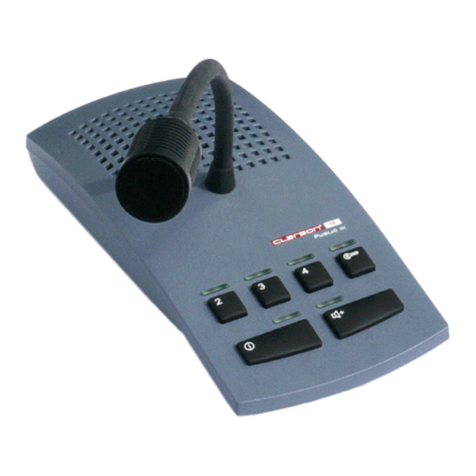
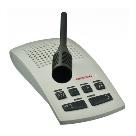
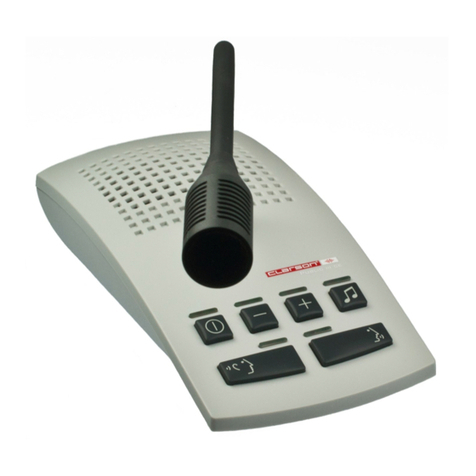
Clarson PUBLIC III User manual

PUBLIC III
Service and Installation Instructions
Service- und Montageanleitung
Instructions de Service et de Montage

Inhaltsverzeichnis
Index
Sommaire
Leistungsmerkmale / Features / Caractéristiques......................................... 3
Mikrofon-Lautsprecher-Einheit anschließen ................................................. 4
Connecting the microphone loudspeaker unit............................................... 4
Brancher le pupitre micro/haut-parleur ......................................................... 4
Standard - Betriebsart .................................................................................. 5
Standard operating mode............................................................................. 5
Mode opératoire standard ............................................................................ 5
Push to talk - Betriebsart ............................................................................. 6
Push to talk mode......................................................................................... 6
Mode opératoire appuyer pour parler ........................................................... 6
Boost - Betriebsart........................................................................................ 7
Boost mode.................................................................................................. 7
Mode booster ............................................................................................... 7
Betriebsart wechseln (Standard - Push to talk - Boost)................................. 8
Changing the operating mode (standard - push to talk -
boost ) ................... 8
Changer le mode opératoire (standard - appuyer pour parler - booster ...... 8
Publikumsposition wählen / Tür öffnen ........................................................ 9
Selecting a public side position / door lock release....................................... 9
Sélectionner une position côté public / commande de gâche ....................... 9
Headset/Handset-Schnittstelle aktivieren ................................................... 10
Activating the headset/handset interface .................................................. 10
Activer l´interface micro-casque/combiné .................................................. 10
Headset/Handset-Schnittstelle aktiviert...................................................... 11
Headset/handset interface activated .......................................................... 11
Interface micro-casque/combiné activée .................................................... 11
Montageanleitung.................................................................................. 12/13
Einstellung.................................................................................................. 14
Belegung der Anschlussbuchsen an der Zentraleinheit und Legende ........ 15
Installation Instructions.......................................................................... 16/17
Adjustment ................................................................................................. 18
Assignment of terminals at the central unit and legend .............................. 19
Instructions de Montage ........................................................................ 20/21
Réglage...................................................................................................... 22
Brochage des prises de l´unité centrale et légende.................................... 23
2

Leistungsmerkmale / Features / Caractéristiques
Offenes Gegensprechen
Temporäres Erhöhen der Hörlautstärke
Stummschaltung des Service-Mikrofons (Push to talk)
Getrennt einstellbare Einschaltempfindlichkeit (Squelch) für Service- und Publikumsmikrofon
Servicefreundliche RJ45-Anschlusstechnik
Erhöhte Störsicherheit durch symmetrische Audio Ein- und Ausgänge
Geringe Leistungsaufnahme im ausgeschalteten Zustand (< 0,2 W)
Separate Induktionsverstärker für Service- und Publikumsseite *
Service-Induktionsverstärker kann auch für die Publikumsseite genutzt werden *
Bis zu 2 Servicepositionen *
Bis zu 4 Publikumspositionen *
Meldemöglichkeit (Gong) für Publikumspositionen mit einstellbarer Gonglautstärke *
Türöffnertaste *
Schnittstelle für Headset/Handset, Hörlautstärke einstellbar *
Einfaches Wechseln der Betriebsarten Standard, Push to talk, Boost
* Option
Open duplex technology
Temporary volume increase
Microphone mute on service side (Push to talk)
Individual service and public side microphone squelch sensitivity control
Fast and error free installation via RJ45 sockets
Increased interference immunity due to balanced audio in- and outputs
Low power consumption when system is switched off (< 0,2 W)
Separate service and public side induction amplifier *
Service side induction amplifier also usable for public side *
Up to 2 service side positions *
Up to 4 public side positions *
Call button (gong) for public side positions with gong volume control *
Door lock release button *
Headset/handset interface with volume control *
Easy mode changeover standard, push to talk, boost
* Option
Interphonie en duplex intégral
Augmentation temporaire du volume sonore
Verrouillage micro côté service (Push to talk)
Réglage individuel de la sensibilité du micro (squelch) côté service et public
Maintien simple par prises RJ45
Protection élevée contre les parasites par des entrées et sorties audio symétriques
Puissance absorbée faible hors service (< 0,2 W)
Amplificateur d´induction séparé pour côté service et public *
Amplificateur côté service aussi utilisable pour coté public *
Jusqu´à 2 positions côté service *
Jusqu´à 4 positions côté public *
Touche d´appel (carillon digital) sur positions public avec réglage volume carillon digital *
Touche commande de gâche *
Interface micro-casque/combiné avec réglage volume *
Changement simple des modes opératoires standard, appuyer pour parler, booster
*Option
D
E
F
3

Mikrofon-Lautsprecher-Einheit anschließen
Connecting the microphone loudspeaker unit
Brancher le pupitre micro/haut-parleur
Brancher le câble sur prise 1 (indispensable), reliant le pupitre micro/hp avec
l´unité centrale.
Brancher le câble sur prise 2 au cas où le pupitre micro/hp est muni d´un
micro-casque ou combiné.
Brancher le micro-casque/combiné sur prise
F
Link the microphone loudspeaker unit with the central unit at jack 1 (indispensable
connection).
Plug the cable into jack 2if the microphone loudspeaker unit is configurated for
headset/handset operation.
Connect the headset/handset at jack
E
Buchse 1 mit der Zentraleinheit verbinden. Diese Verbindung wird immer benötigt.
Buchse 2 mit der Zentraleinheit verbinden.
Diese Verbindung ist nur notwendig, wenn an der Mikrofon-Lautsprecher-Einheit ein
Headset oder Handset angeschlossen werden soll.
An Buchse kann ein Headset oder Handset angeschlossen werden.
D
4

STANDARD - Betriebsart
STANDARD Operating Mode
Mode Opératoire STANDARD
Einschalten:
Taste betätigen,
die LED oberhalb der
Taste leuchtet.
Ausschalten:
Taste betätigen, LED
oberhalb der Taste geht
aus.
Switching on:
Push button , the led
above the button lights up.
Switching off:
Push button , the led
above the button goes out.
Mise en marche:
Appuyer sur la touche ,
la led au-dessus de la
touche s´allume.
Arrêt:
Réappuyer sur la touche ,
la led au-dessus de la
touche s´éteint.
E
F
D
Anlage ein-/ausschalten
Switching ON/Off
Mise en marche/arrêt
Taste gedrückt halten.
LED oberhalb der Taste
leuchtet.
Die Hörlautstärke auf der
Serviceseite wird um 10dB
angehoben und auf der
Publikumsseite um 10dB
gesenkt.
Push and hold button .
The led above the button
lights up.
The volume on the service
side is increased by 10dB
and at the same time
decreased by 10dB on
the public side.
Appuyer la touche en
continu.
La led au-dessus de la
touche s´allume.
Le volume d´écoute sur le
côté service est augmenté
par 10dB et en même
temps diminué par 10db
sur le côté public.
E
F
D
Hörlautstärke anheben
Volume increase
Augmenter le volume
5

PUSH TO TALK - Betriebsart
PUSH TO TALK Mode
Mode Opératoire APPUYER POUR PARLER
Anlage ein-/ausschalten
Switching the system ON/OFF
Mise en marche/arrêt
Einschalten:
Taste betätigen,
LED oberhalb der Taste blinkt.
Ausschalten:
Bei gedrückter Taste (LED
oberhalb der Taste leuchtet)
Taste kurz antippen.
LEDs oberhalb der Tasten
gehen aus.
Switching on:
Push button , the led above
the button flashes.
Switching off:
Push and hold button (the led
above the button lights up) and
simultaneously tap on button .
The leds above buttons go
out.
Mise en marche:
Appuyer sur la touche , la led
au-dessus de la touche clignote.
Arrêter:
Appuyer la touche en continu
(la led au-dessus de la touche
s´allume) et en même temps
appuyer brièvement sur la
touche .
Les leds au-dessus des touches
s´éteignent.
D
E
F
Sprechen
Speak
Parler
Taste gedrückt halten.
LED oberhalb der Taste
leuchtet.
Push and hold button .
The led above the button
lights up.
Appuyer la touche en
continu.
La led au-dessus de la
touche s´allume.
D
E
F
Hörlautstärke anheben
Volume increase
Augmenter le volume
Taste gedrückt halten.
LED oberhalb der Taste
leuchtet.
Die Hörlautstärke auf der
Serviceseite wird um 10dB
angehoben und auf der
Publikumsseite um 10dB
gesenkt.
Press and hold button .
The led above the button
lights up.
The volume on the service
side is increased by 10dB
and at the same time
decreased by 10dB on
the public side.
Appuyer la touche en
continu.
La led au-dessus de la
touche s´allume.
Le volume d´écoute sur le
côté service est augmenté
par 10dB et en même
temps diminué par 10db
sur le côté public.
E
F
D
6

BOOST - Betriebsart
BOOST MODE
Mode BOOSTER
Hören / Sprechen
Listen / Speak
Ecouter / Parler
Anlage ein-/ausschalten
Switching the system ON/OFF
Mise en marche/arrêt
Einschalten:
Taste betätigen.
LEDs oberhalb der Tasten
leuchten.
Ausschalten:
Taste betätigen,
LEDs oberhalb der Tasten
gehen aus.
Switching on:
Push button .
The leds above buttons
light up.
Switching off:
Push button .
The leds above buttons
go out.
Mise en marche:
Appuyer sur la touche .
Les leds au-dessus des touches
s´allument.
Arrêter:
Appuyer sur la touche .
Les leds au-dessus des touches
s´éteignent.
D
E
F
In dieser Betriebsart ist die Hörlaut-
stärke auf der Serviceseite um 10dB
angehoben und auf der Publikumssei-
te um 10dB gesenkt. LED oberhalb
der Taste leuchtet.
Zum Sprechen Taste gedrückt
halten. Die Hörlautstärke auf der Ser-
viceseite wird um 10dB gesenkt und
auf der Publikumsseite um 10dB an-
gehoben.
LED oberhalb der Taste geht aus.
In this mode the volume on the servi-
ce side is increased by 10dB and de-
creased by 10dB on the public side.
The led above button lights up.
For speaking push and hold button .
The volume on the service side is
decreased by 10dB and increased by
10dB on the public side.
The led above the button goes out.
Dans ce mode le volume d´écoute sur
le côté service est augmenté par
10dB et diminué par 10db sur le côté
public.
La led au-dessus de la touche
s´allume.
Appuyer la touche en continu pour
parler. Le volume d´écoute sur le côté
service est diminué par 10dB et aug-
menté par 10dB sur le côté public.
La led au-dessus de la touche
s´éteint.
D
E
F
7

Betriebsart wechseln
Changing the Operating Mode
Changer le Mode Opératoire
Standard - Betriebsart
Standard Operating Mode
Mode Opératoire Standard
Push to talk - Betriebsart
Push to talk Mode
Mode Appuyer pour parler
Boost -Betriebsart
Boost Mode
Mode Booster
Anlage ausschalten.
Taste so lange gedrückt
halten, bis LED einmal
blinkt.
Um wieder zur Standard-
Betriebsart zu wechseln,
Vorgang wiederholen oder
Spannungsversorgung kurz
unterbrechen.
Switch the system off.
Push and hold button till
the led flashes once.
To return to standard mode,
push button again or
disconnect the system from
the mains for a moment.
Mettre le système hors
tension.
Laisser la touche appuyée
jusqu´à ce que la led clignote
une fois.
Pour retourner au mode stan-
dard, réappuyer sur la touche
ou retirer le câble d´ali-
mentation pendant quelques
instants.
Anlage ausschalten.
Taste so lange gedrückt
halten bis LED zweimal
blinkt.
Um wieder zur Standard-
Betriebsart zu wechseln,
Vorgang wiederholen oder
Spannungsversorgung kurz
unterbrechen.
Switch the system off.
Push and hold button till
the led flashes twice.
To return to standard mode,
push button again or
disconnect the system from
the mains for a moment.
Mettre le système hors
tension.
Laisser la touche appuyée
jusqu´à ce que la led clignote
deux fois.
Pour retourner au mode stan-
dard, réappuyer sur la touche
ou retirer le câble d´ali-
mentation pendant quelques
instants.
Nach Inbetriebnahme und
Betätigung der Taste
arbeitet die Anlage in der
Standard-Betriebsart.
After starting the system
and pushing button ,
the system operates in
standard mode.
Le système fonctionne en
mode standard après mise
en route et appui sur la
touche .
D
E
F
D
E
F
D
E
F
8

OPTIONEN / OPTIONS
Publikumsposition wählen / Tür öffnen
Selecting a Public Side Position / Door Lock Release
Sélectionner une Position Côté Public/Commande de Gâche
Publikumspositionen 2 / 3 / 4
Public Side Positions 2 / 3 / 4
Positions Côté Public 2 / 3 / 4
LED oberhalb der Taste 2/3/4 blinkt,
wenn an der Publikumsposition
2/3/4 die Meldetaste betätigt wird.
Das Betätigen der Taste 2/3/4 baut
eine Verbindung zur betreffenden
Publikumsposition auf.
LED oberhalb der Taste 2/3/4
leuchtet.
If the call button on public side
position 2/3/4 is activated, the
led above the button 2/3/4 on the
microphone loudspeaker unit
flashes.
Communication with public side
position 2/3/4 is established by
activating the button.
The corresponding led above the
button lights permanently.
Si la touche d´appel sur la position
côté public 2/3/4 est appuyée, la led
correspondante au-dessus de la
touche 2/3/4 sur le pupitre micro/hp
clignote.
La communication est établie en
appuyant sur la touche 2/3/4 et la
led au-dessus de la touche est
allumée en continu.
D
E
F
Taste gedrückt halten.
LED oberhalb der Taste leuchtet.
Abhängig von der gewählten
Publikumsposition wird der
entsprechende Türöffner aktiviert.
Push and hold button .
The led above the button lights up.
The door lock release function on
the corresponding public side
position is activated.
Appuyer la touche en continu.
La led au-dessus de la touche
s´allume.
La fonction commande de gâche
sur la position public correspon-
dante est activée.
E
F
D
Tür öffnen
Door Lock Release
Commande de Gâche
9

OPTIONEN / OPTIONS
HEADSET/HANDSET - Schnittstelle aktivieren
Activating the HEADSET/HANDSET Interface
Activer l´interface MICRO-CASQUE/COMBINE
Serviceseite
Service Side
Côté Service
Publikumsseite
Public Side
Côté Public
Anlage ausschalten.
Taste so lange gedrückt halten
bis LED oberhalb der Taste
einmal blinkt.
Zum Deaktivieren Vorgang wie-
derholen oder Spannungsversor-
gung kurz unterbrechen.
Durch einen externen Kontakt,
z.B. in der Handsetablage, kann
dieser Vorgang auch automati-
siert werden.
Switch the system off.
Push and hold button till the
led above the button flashes
once.
Return to previous mode by re-
peating the above mentioned
steps or by disconnecting the
system from the mains for a
moment.
This process can be automized,
e.g. by an external contact in the
handset support.
Mettre le système hors tension.
Laisser la touche appuyée
jusqu´à ce que la led au-dessus
de la touche clignote une fois.
Pour annuler, réappuyer sur la
touche ou retirer le câble d´ali-
mentation pendant quelques in-
stants.
Cette opération peut être auto-
matisée par l´intermédiaire d´un
contact externe p. ex. dans le
support du combiné.
D
E
F
Anlage ausschalten.
Taste so lange gedrückt halten
bis LED oberhalb der Taste
zweimal blinkt.
Zum Deaktivieren Vorgang wie-
derholen oder Spannungsversor-
gung kurz unterbrechen.
Durch einen externen Kontakt,
z.B. in der Handsetablage, kann
dieser Vorgang auch automati-
siert werden.
Switch the system off.
Push and hold button till the
led above the button flashes
twice.
Return to previous mode by re-
peating the above mentioned
steps or by disconnecting the
system from the mains for a
moment.
This process can be automized,
e.g. by an external contact in the
handset support.
Mettre le système hors tension.
Laisser la touche appuyée
jusqu´à ce que la led au-dessus
de la touche clignote deux fois.
Pour annuler, réappuyer sur la
touche ou retirer le câble
d´alimentation pendant quelques
instants.
Cette opération peut être auto-
matisée par l´intermédiaire d´un
contact externe p. ex. dans le
support du combiné.
D
E
F
10

OPTIONEN / OPTIONS
HEADSET/HANDSET - Schnittstelle aktiviert
HEADSET/HANDSET Interface activated
Interface MICRO-CASQUE/COMBINE activée
Publikumsseite
Public Side
Côté Public
Mikrofon und Lautsprecher
auf der Publikumsseite sind
nicht aktiv.
Das Blinken der LED
(1 sec an - 0,2 sec aus)
oberhalb der Taste
signalisiert diesen Zustand.
The microphone and loud-
speaker on the public side
are not activated.
The flashing led (1 sec on -
0,2 sec off) above button
indicates this mode.
Le microphone et le haut-
parleur sur le côté public
sont coupés.
La led au-dessus de la
touche clignote
(1 sec allumée - 0,2 sec
éteinte) indiquant l´étát du
système.
Serviceseite
Service Side
Côté Service
Service + Publikumsseite
Service + Public Side
Côté Service + Public
D
Mikrofon und Lautsprecher
auf der Servicesseite sind
nicht aktiv.
Das Blinken der LED
(0,5 sec an - 0,5 sec aus)
oberhalb der Taste
signalisiert diesen Zustand.
The microphone and loud-
speaker on the service side
are not activated.
The flashing led (intervals
of 0,5 sec) above button
indicates this mode.
Le microphone et le haut-
parleur sur le côté service
sont coupés.
La led au-dessus de la
touche clignote (intervalle
de 0,5 sec) indiquant l´état
du système.
D
E
F
E
F
Mikrofon und Lautsprecher
auf der Publikums- und
Servicesseite sind nicht
aktiv.
Das Blinken der LED
(1 sec an - 0,2 sec aus -
0,2 sec an - 0,2 sec aus)
oberhalb der Taste
signalisiert diesen Zustand.
The microphone and loud-
speaker on public and
service side are not activa-
ted.
The flashing led
(1 sec on - 0,2 sec off -
0,2 sec on - 0,2 sec off)
above button indicates
this mode.
Le microphone et le haut-
parleur sur le côté public
et service sont coupés.
La led au-dessus de la
touche clignote
(1 sec allumée - 0,2 sec
éteinte - 0,2 sec allumée -
0,2 sec éteinte) indiquant
l´état du système.
D
E
F
11

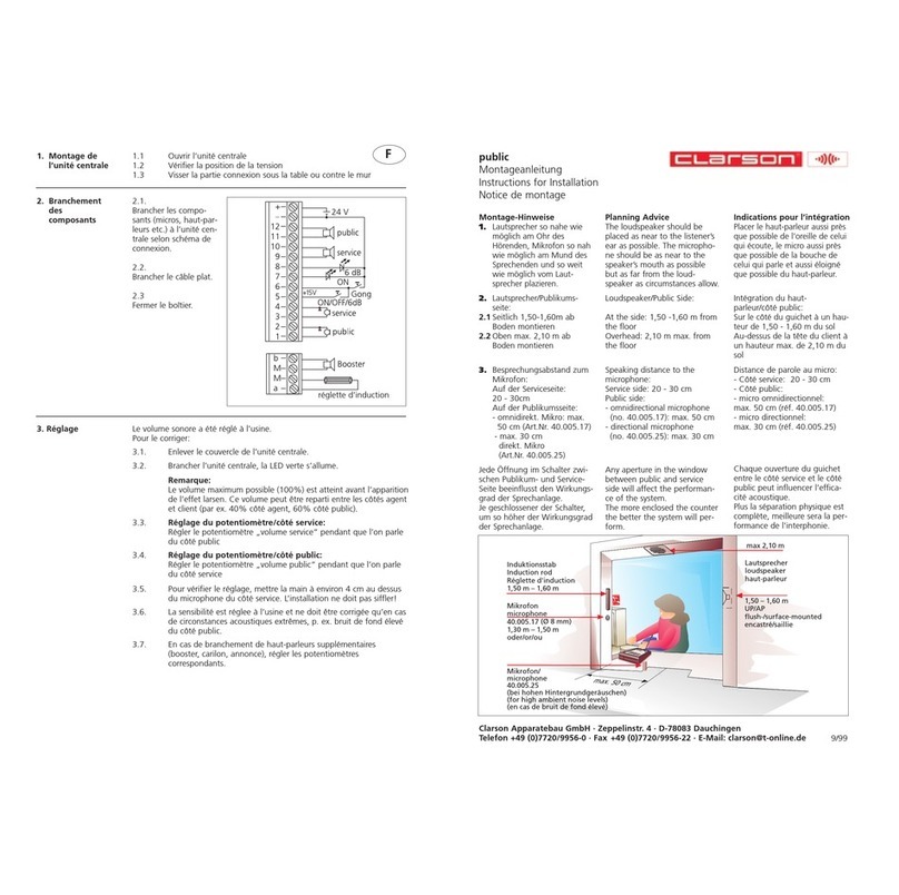
Montage-Hinweise
1.Jede Öffnung im Schalter zwischen Publikums- und Serviceseite beeinflusst den
Wirkungsgrad der Sprechanlage.
Je geschlossener der Schalter, desto höher der Wirkungsgrad der Sprechanlage.
2.Lautsprecher so nah wie möglich am Ohr des Hörenden,
Mikrofon so nah wie möglich am Mund des Sprechenden
und so weit wie möglich vom Lautsprecher entfernt plazieren.
3. Lautsprecher/Publikumsseite (ab Boden): seitlich 1,50 - 1,60 m, oben max. 2,10 m
Mikrofon/Publikumsseite (ab Boden): 1,30 - 1,50 m,
Mindestabstand zwischen Mikrofon und Lautsprecher: 0,5 m.
4. Besprechungsabstand zum Mikrofon:
Serviceseite: 10 - 30 cm
Publikumsseite:
• omnidirektionelles Mikrofon (40.005.017/40.005.053): max. 50 cm
•direktionelles Mikrofon (40.005.050/40.005.051): max. 30 cm
•direktionelles Mikrofon 40.005.020: max. 50 cm
Montageanleitung
12
Mikrofon
40.005.020
extrem vandalensicher

+
-
GND
Mikrofon
3 6 7
Lautsprecher
4 5
Option Loop
(Induktionsstab)
4 5 service 3 6 public
Bu1 Bu2
1. Montage
der
Zentraleinheit
1.1 RJ45 Dose(n) montieren (1 Dose je Publikumsposition)
1.2 Zentraleinheit mit 4 Schrauben an der Wand oder unter dem
Tisch vormontieren
2. Anschluss
der
Komponenten
2.1 Mikrofone und Lautsprecher montieren, an RJ45 Dose
anschließen (Bild 1). RJ45 Dose (Bu1) und Zentraleinheit
(Buchse Public) mit Patchkabel verbinden (Bild 2).
OPTIONEN: Meldetaste, Gong, Relais, Loop (Induktionsstab)
ebenfalls an RJ45 Dose anschließen (s. Seite 15).
RJ45 Dose (Bu2) und Zentraleinheit (Buchse Loop) mit
Patchkabel verbinden.
2.2 Mikrofon-Lautsprecher-Pult (Buchse 1) und Zentraleinheit
(Buchse Service) mit Patchkabel verbinden (Bild 2).
OPTION: Headset/Handset
Mikrofon-Lautsprecher-Pult (Buchse 2) und Zentraleinheit
(Buchse Headset) mit Patchkabel verbinden sowie *Headset/
Handset mit Mikrofon-Lautsprecher-Pult (Buchse verbinden.
* Entfällt, wenn Headset/Handset direkt mit der Zentraleinheit
(Buchse Headset) verbunden wird.
2.3 Netzgerät mit Zentraleinheit (Buchse DC power) verbinden (Bild 2).
Bild 1
13

3. Einstellung
Die Potentiometer befinden sich an der Rückseite der Zentraleinheit. Die Lautstärke
wurde im Werk eingestellt. Bitte belassen Sie zunächst diese Werksvoreinstellungen
und nehmen Sie das Gerät in Betrieb. Erst wenn Sie die ordnungsgemäße Funktion des
Geräts überprüft haben, sollten Sie ggfs. zur Optimierung der Einstellungen mit einem
2,5 mm Schraubendreher (nicht kleiner als 2 mm) wie folgt verfahren:
Bild 2
3.1 Zentraleinheit aushängen und zur bequemen Einstellung auf den Tisch legen.
3.2 Anlage mit Taste einschalten. Die grüne LED leuchtet.
Hinweis:
Die maximal verteilbare Lautstärke (100 %) ist auf die akustische Rückkopplung
begrenzt. Diese kann jedoch innen und außen ungleichmäßig verteilt werden
(z. B. Serviceseite 40 %, Publikumsseite 60 %).
3.3 Einstellung Serviceseite:
Potentiometer drehen während auf der Publikumsseite gesprochen wird.
3.4 Einstellung Publikumsseite:
Potentiometer drehen während auf der Serviceseite gesprochen wird.
3.5 Zur Prüfung der Einstellung halten Sie die Hand ca. 4 cm vor dem Mikrofon auf der
Serviceseite. Es darf keine Rückkopplung entstehen!
3.6 Die Einschaltempfindlichkeit des Service-/Publikummikrofons sollte nur bei extremen
akustischen Verhältnissen, z. B. bei hohem Lärm auf der Publikumsseite, nachreguliert
werden.
3.7 Falls zusätzliche Komponenten angeschlossen sind, z. B. weitere Publikumspositionen,
Headset etc., sind die hierfür vorgesehenen Potentiometer einzustellen.
3.8 Zentraleinheit einhängen und definitiv festschrauben.
14

Legende
PUB
PUB3
PUB4
SER2
SER
PUB2
PUB
SER
SER2
SER
PUB
Lautstärkeeinsteller für Serviceposition 2
Lautstärkeeinsteller für Headset/Handset Serviceposition 2
Lautstärkeeinsteller für Serviceposition 1
Lautstärkeeinsteller für Publikumsposition 1
Lautstärkeeinsteller für Publikumsposition 2
Lautstärkeeinsteller für Publikumsposition 3
Lautstärkeeinsteller für Publikumsposition 4
Einsteller für Einschaltempfindlichkeit Publikumsmikrofon
Einsteller für Einschaltempfindlichkeit Servicemikrofon
Lautstärkeeinsteller für Headset/Handset Serviceposition 1
Lautstärkeeinsteller für Headset/Handset Publikumsposition 1
Lautstärkeeinsteller für Gong- Signal
Ein/Aus, Push to Talk- aktivieren, Boost- aktivierenBetriebsart Betriebsart
Laut hören, Headset/Handset- Betr aktiviereniebsart
2
3
4
Publikumsposition 2
Publikumsposition 3
Publikumsposition 4
Türöffner
Mikrofon- Lautsprecherpult
Zentraleinheit
Belegung der Anschlussbuchsen an der Zentraleinheit
+15VDC / 100mA
OPTIONAL
HEADSET SWITCH
OPTIONAL
HANDSET SWITCH
OPTIONAL
GONG SIGNAL
OPTIONAL
RELAY SWITCH
- CONTROL OUTPUT
max. 24VDC / 250mA
DC POWER
15V / 1A
SERVICE SIDE
PERIPHERALS
ACTIVE
CONTROL
SERVICE SIDE
PERIPHERALS
PA SS I VE
CONTROL
OPTIONAL
SERVICE SIDE
HEADSET
PUBLIC SIDE
PERIPHERALS
OPTIONAL
PUBLIC SIDE
HANDSET
OPTIONAL
INDUCTION
LOOP
+15VDC
GND
GND
RS485 b
RS485 a
PUBLIC SIDE
SERVICE SIDE
+15VDC / 100mA
GND
GND
220
220
8k2
RX
1
11
1
1
2
22
2
2
3
33
311
3
4
44
422
4
5
55
533
5
6
66
644
6
7
77
78
88
8
Public iii
CLARSON Apparatebau GmbH, Zeppelinstraße 4, D 78083 Dauchingen, http://www.clarson.de
15

Planning Advice
1. Any aperture in the window between public and service side will affect the
performance of the system.
The more enclosed the counter, the better the system will perform.
2.The loudspeaker should be placed as near to the listener´s ear as possible.
The microphone should be as near to the speaker´s mouth as possible,
but as far from the loudspeaker as circumstances allow.
3. Loudspeaker/public side (from the ground): at the side 1,50-1,60 m,overhead max.2,10 m
Microphone/public side (from the ground): 1,30 - 1,50 m,
minimum distance between microphone and loudspeaker: 0,5 m
4. Speaking distance to the microphone:
Service side: 10 - 30 cm
Public side:
• omnidirectional microphone (40.005.017/40.005.053): max. 50 cm
• directional microphone (40.005.050/40.005.051): max. 30 cm
• directional microphone 40.005.020: max. 50 cm
Installation Instructions
16
microphone
40.005.020
highly vandal proof

+
-
GND
microphone
3 6 7
loudspeaker
4 5
optional loop
(induction rod)
4 5 service 3 6 public
Bu1 Bu2
1. Installation
of the
central unit
1.1 Install the RJ45 socket/s (1 socket for each public side position)
1.2 Screw the central unit provisionally on the wall or under the
desk (4 screws).
2. Installation
of
components
2.1 Install the microphones and loudspeakers and connect them to
the RJ45 socket (pict. 1). Link the RJ45 socket (Bu1 ) with the
central unit (jack public) via patch cable (pict. 2).
OPTIONS: Connect any additional equipment, e. g. call button,
gong, relay box, loop (induction rod) also to the RJ45 socket
(see page 19). Link the RJ45 socket (Bu2) with the central unit
(jack loop) via patch cable.
2.2 Link the microphone loudspeaker unit (jack 1) with the central
unit (jack service) via patch cable (pict. 2).
OPTION: Headset/Handset
Link the microphone loudspeaker unit (jack 2) with the central
unit (jack headset) via patch cable and *connect the headset/
handset to the microphone loudspeaker unit (jack ).
* Not applicable if the headset/handset is connected directly to
the central unit (jack headset).
2.3 Connect the power supply to the central unit (DC jack) (pict.2).
pict. 1
17

pict. 2
3. Adjustment
The potentiometers are located at the rear of the central unit. They have been pre-set
at the factory and do not need to be adjusted under normal conditions. Do not turn
potentiometers before the system has been installed and is in working order.
If potentiometers need to be set, use a 2.5 mm (not smaller than 2 mm) flat blade
screwdriver. For readjustment/optimisation proceed as follows:
3.1 Remove the central unit and place it on the table for comfortable adjustment.
3.2 Push button to switch the system on. The green led lights up.
Note:
Max. volume (100 %) is reached slightly before feedback. This volume can be
distributed between service and and public side (e. g. 40 % service side, 60 %
public side).
3.3 Volume/Service Side:
Tune potentiometer whilst somebody is speaking on the public side.
3.4 Volume/Public Side:
Tune potentiometer whilst somebody is speaking on the service side.
3.5 Place your hand about 4 cm over the center hole of the microphone on the service
side. Feedback must be avoided!
3.6 The sensitivity of the service/public side microphone is adjusted in our factory.
It should only be changed in case of extreme acoustical conditions, e. g. in case of
high ambient noise levels on the public side.
3.7 Tune the potentiometers of additionally connected components, e. g. further public
positions, headset etc.
3.8 Suspend and definitely screw the central unit.
18

Legend
PUB
PUB3
PUB4
SER2
SER
PUB2
PUB
SER
SER2
SER
PUB
service side volume control, position 2
service side headset/handset volume control, position 2
service side volume control, position 1
public side volume control, position 1
public side volume control, position 2
public side volume control, position 3
public side volume control, position 4
public side microphone squelch sensitivity control
service side microphone squelch sensitivity control
service side headset/handset volume control, position 1
public side headset/handset volume control, position 1
gong volume control
ON/OFF, PUSH TO TALK, start BOOST operationchange to
volume increase, change to headset/handset
2
3
4
public position 2
public position 3
public position 4
door lock release
Microphone Loudspeaker Unit
Central Unit
Assignment of terminals at the central unit
+15VDC / 100mA
OPTIONAL
HEADSET SWITCH
OPTIONAL
HANDSET SWITCH
OPTIONAL
GONG SIGNAL
OPTIONAL
RELAY SWITCH
- CONTROL OUTPUT
max. 24VDC / 250mA
DC POWER
15V / 1A
SERVICE SIDE
PERIPHERALS
ACTIVE
CONTROL
SERVICE SIDE
PERIPHERALS
PA SS I VE
CONTROL
OPTIONAL
SERVICE SIDE
HEADSET
PUBLIC SIDE
PERIPHERALS
OPTIONAL
PUBLIC SIDE
HANDSET
OPTIONAL
INDUCTION
LOOP
+15VDC
GND
GND
RS485 b
RS485 a
PUBLIC SIDE
SERVICE SIDE
+15VDC / 100mA
GND
GND
220
220
8k2
RX
1
11
1
1
2
22
2
2
3
33
311
3
4
44
422
4
5
55
533
5
6
66
644
6
7
77
78
88
8
Public iii
CLARSON Apparatebau GmbH, Zeppelinstraße 4, D 78083 Dauchingen, http://www.clarson.de
19

Indications pour l´intégration
1.Chaque ouverture du guichet entre le côté service et le côté public peut influencer
l´efficacité acoustique.
Plus la séparation physique est complète, meilleure sera la performance de
l´interphonie.
2.Placer le haut-parleur aussi près que possible de l´oreille de celui qui écoute et
le microphone aussi près que possible de la bouche de celui qui parle et aussi
éloigné que possible du haut-parleur.
3. Haut-parleur/côté public (hauteur du sol): sur le côté 1,50 - 1,60 m,
au-dessus de la tête max. 2,10 m
Microphone/côté public (hauteur du sol): 1,30 - 1,50 m
distance minimum entre microphone et haut-parleur: 0,5 m.
4. Distance de parole au micro:
côté service: 10 - 30 cm
côté public:
• microphone omnidirectionnel (40.005.017/40.005.053): max. 50 cm
• microphone directionnel (40.005.050/40.005.051): max. 30 cm
• microphone directionnel 40.005.020: max. 50 cm
Instructions de montage
20
microphone
40.005.020
extrêmement antivandale
Other manuals for PUBLIC III
3
Table of contents
Other Clarson Intercom System manuals
