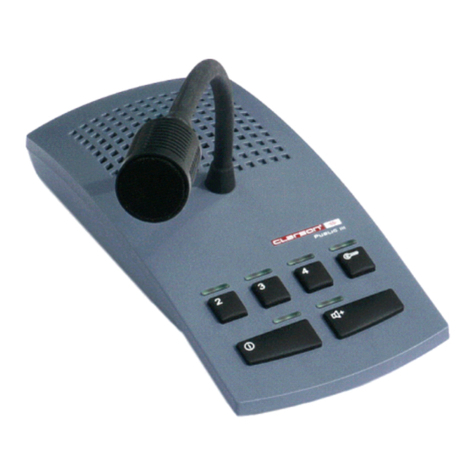
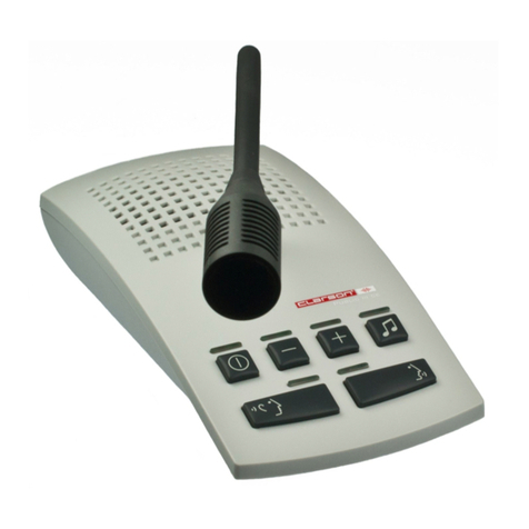
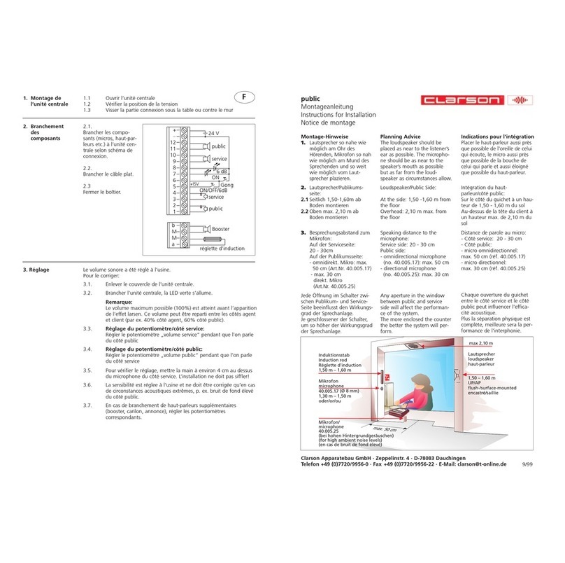
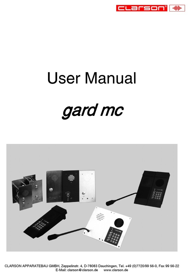
Clarson OUBLIC IV User manual

Installaon instrucons .......................................................................................................................... 3/4
Key funcons, LED signals...........................................................................................................................5
Volume control...........................................................................................................................................5
PTT mode....................................................................................................................................................5
Boost mode ................................................................................................................................................5
Headset operaon......................................................................................................................................6
Service-sengs...........................................................................................................................................6
......................................................................................................................................................................
......................................................................................................................................................................
......................................................................................................................................................................
• Full duplex mode
• PTT mode
• Boost mode
• Headset interface
• Audible signal (1)
• Switching output (Open Drain) for example: door opener
• Footswich interface (2)
• AEC (Automac echo cancellaon)
• NR (Noise reducon)
• NG (Noise gate)
• Individual adjustment of the volume for listening / speaking / headset / via +/- keys
• Balanced microphone inputs and amplier outputs
Voltage/current .................................................................................................................... 15VDC/700mA
Maximum power consumpon (limited by power supply) ................................................................ <15W
Power consumpon in OFF-mode................................................................................................... <0.15W
Maximum output power at 8Ω/channel................................................................................................. 5W
Minimum loudspeaker impedance.......................................................................................................... 8Ω
Temperature:.................................................................................................................................10 - 40 °C
Humidity:..................................................................................................... 20 % to75 % (non condensing)
Air pressure: ................................................................................................................700 hPa to 1060 hPa
(1)Custom audio playback possible (.wav le)
(2)Remote control of the buon
Technical Data
Features
Table of Contents
Service and Installaon Manual
35.054.440.002 05/2019

Basic components Service side
2
Power supply GPP10 Medical, 100-240V /50-60Hz,
2m cable, labels 32.054.803.001, 32.054.803.002
Microphone-loudspeaker unit
RAL Colour 7035
Label 32.054.440.001
40.054.440.001
RJ45 juncon box
Label 32.054.305.001
Installaon material 40.054.874
40.054.305.001
~
RJ45 patch cable KAT5e, 3m
labels 32.054.327.001, 32.054.327.002
40.054.327.001
40.054.803.002
3
Components public side
Omnidireconal electret built-in microphone
EM 258, in stainless steel capsule, Ø 8 x 5.5 mm,
3.5 m microphone cable
Miniature speaker system MKS-26 / WS
8 Ohm, 10 Wa, 5 m speaker cable 11.008.03
40.006.147
Loudspeaker ush mount, 5 Wa, 8 Ohm with ush
mount box, anodised aluminium cover,
5 m loudspeaker cable 11.008.03
40.006.102
Direconal electret microphone
in stainless steel housing including microphone holder
made of stainless steel, safety pin, 25 mm
Threaded tube, 3.5 m microphone cable
40.005.020.005
40.005.017.005

4
Assembly public areaAssembly service area
5
127
GND
Switching output
Signal buon
Planning Advice
1. Any aperture in the window between public and service side will affect the
performance of the system.
The more the counter is enclosed, the better the system will perform.
2.The loudspeaker should be placed as close as possible to the listener´s ear.
The microphone should be as close as possible to the speaker´s mouth,
and as far as possible from the loudspeaker as circumstances allow.
3. Loudspeaker/public area (from the ground): side 1,50-1,60 m, overhead max.2,10 m
Microphone/public side (from the ground): 1,30 - 1,50 m,
minimum distance between microphone and loudspeaker: 0,5 m
4. Speaking distance from the microphone:
Service area: 10 - 20 cm
Public area:
• omnidirectional microphone: max. 50 cm
• directional microphone: max. 30 cm
Assembly variant
Microphone 40.005.020.005
Micophone 40.005.017.005
loudspeaker flush-/surface mounted
loudspeaker
or

6
Key Funcon LED signal Condion Intercom system
operang status on switched on
o switched o
ashing PTT mode
Boost on open listening is acvated
o open listening is deacvated
Volume on, brightness will be increased Increase volume
ashing maximum volume
Volume on, brightness will be reduced reduce volume
ashing minimum volume
Open Drain output on switching output is connected to GND
o switching output is open
Setup mode ashing setup mode is switched on
Adjust the volume:
Use the and buons to set the maximum volume for opmal sound quality at the
service area.
While pressing buon , use the and buons to set maximum volume for opmal
sound quality at the Public area.
PTT operang mode:
The service-microphone will only be switched on when buon is pressed.
To switch o the intercom, press buon while holding buon .
Switch on PTT operang mode:
Switch o the intercom.
Keep the buon pressed unl the LED above the buon ashes.
Switch o PTT operang mode:
Switch o the intercom.
Keep the buon pressed unl the LED above the buon lights up.
Boost mode:
Open listening is switched on, keep buon pressed to speak, open listening will be switched o,
loudspeaking will be switched on.
Switch on Boost mode:
Switch o the intercom.
Keep the buon pressed unl LED above the buon lights up.
Switch o Boost mode:
Switch o the intercom.
Keep the buon pressed unl LED above the buon turns o.
Operaonal Setup/Service
Depending on the local acousc condions, it may be necessary to change the volume
seng range to avoid poor sound quality and feedback.
The following sengs set the maximum volume for the Service and Public area:
Press the buon, the LED above the buon lights up.
Disconnect the patch cable at console socket 1, wait unl all LEDs turn o.
Press and hold the buon to reconnect the patch cable to socket 1 on the console.
Keep the buon pressed (approx. 5 sec.) unl the LED above the buon ashes.
Press the buon, the LED above the buon lights up.
Use the and buons to set the maximum volume for an opmal sound quality at the
Service area.
Press the buon, the LED above the buon turns o.
Press the buon, the LED above the buon lights up.
Use the and buons to set the maximum volume for opmal sound quality at the
Public area.
Press the and buons to the same me unl LEDs above the buons ash briey once
to save the new values.
Press the buon to exit the sengs, all LEDs will turn o.
Trouble shoong:
In case of interference, intercom components should be relocated to increase the distance from
sources of strong electromagnec radiaon.
7
Headset operaon
Switch on temporary headset operaon:
Aer switching on the intercom, the microphone-loudspeaker unit is always acve,
regardless of whether the headset is plugged in or not.
Switching to headset mode is done by plugging in or plugging out and back in again.
Switch on permanent headset operaon:
Turn on the intercom system
Press and hold the buon to plug in the headset.
Release the buon and permanent headset mode is acvated.
Switch o permanent headset operaon:
Switch o the intercom and unplug the headset.
Other Clarson Intercom System manuals
