41000972 iss 07
Fig 3 WIRING DIAGRAM
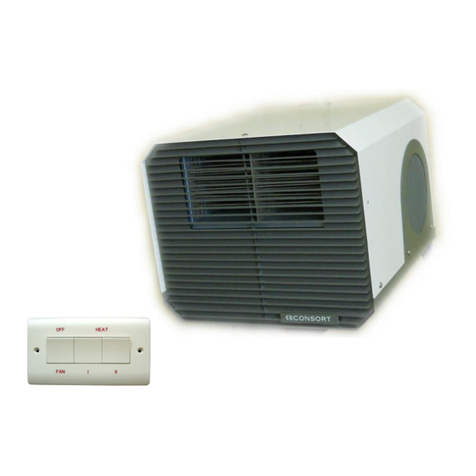
NOTE: This unit is suit ble for remote control oper tion, with the
use of remote control switch p rt no. HE8407. The two
independent feeds must be used on 6kW he ters s shown on the
di gr m.
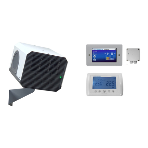
Fig 4 REMOTE CONTROL – HE8407
For safety reasons a sound earth connection must always be made to
the unit before it is put to use. The unit should be wired in
accordance with IEE Regulations for the Electrical Equipment of
Buildings.
NOTE: The unit MUST be reli bly e rthed.
OPERATION
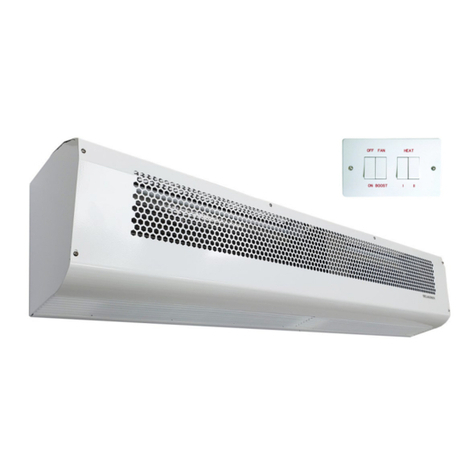
The right hand switch connects the mains supply to the fan motor
(giving a cool airflow) and energises the heat control switches.
HEAT CONTROL HE8230
When the centre switch (marked with a single black dot) is depressed
the heat output is 1.5kW. When the left-hand switch (marked with
two black dots) is depressed the heat output is 3kW. When both
switches are depressed the heat output is 4.5kW.
HEAT CONTROL HE7426
When the centre switch (marked with a single bar) is depressed the
heat output is 3kW. When the left-hand switch (marked with a single
bar) is depressed the heat output is 3kW. When both switches are
depressed the heat output is 6kW.
MAINTENANCE
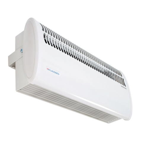
lways ensure that the main external electricity supply is switched
off before attending to the servicing of your Claudgen Screen-Zone
heater.
To obtain best results from your heater it is necessary to avoid the
build up of dust and dirt within the unit and on the air inlet and
discharge grills. For this reason regular cleaning is necessary, paying
particular attention to the removal of dirt build up on the rotor
blades. single drop of light oil should be applied to the motor
bearing from time to time.
PROTECTION (Therm l Cut-out)
The units are protected in the event of fan failure, or an obstruction
of the free airflow, by thermal PTC Self Hold Cut-outs. Having
tripped, the PTC cut-out remains open, effectively switching off the
heating elements, as long as mains power is available inside the
appliance.
TO RESET THE PTC SELF-HOLD CUT-OUT
DO NOT ADJUST BY HAND ANY COMPONENTS
a) The cut-out is reset by switching OFF mains power to the
appliance.
b) llow the appliance to cool for 20 minutes.
c) Restart, switch ON the appliance. If the cut-out trips again a
qualified electrician should be consulted.
TO REPLACE A SWITCH
a) Remove the top cover.
b) Release the three fixings which secure the switch bracket to the
right hand side of the main case.
c) Remove the push-on connectors, noting their position.
d) Remove by compressing the plastic retaining tabs, and lifting
out the switch.
e) Insert the new switch, refit and push on connectors in the
correct order, test and reassemble.
TO REPLACE THE FAN HEATER ASSEMBLY
a) Remove the top cover.
b) Disconnect the internal wiring from the main terminal block and
earth stud.
c) Release the three fixings which secure the switch bracket to the
right hand of the main case.
d) Remove the four nuts and washers fixing the fan heater
assembly to the back of the case.
e) The fan heater assembly can now be eased forward and
removed from the heater case.
f) Fit replacement fan heater and reassemble in reverse order.
SPARES
It is essential when ordering spares or replacement parts to state the
model number and the serial number on the rating place fixed to the
top of the unit.
In the interest of progress the Company reserve the right to vary
specifications from time to time without notice. The material listed
is offered subject to the Company’s General Conditions of Sale, a
copy of which can be obtained on request.
NOTE: DO NOT COVER ny of the ir inlet or outlet grills, t ny
time.

