manuals.online logo
Brands
  1. Home
  2. •
  3. Brands
  4. •
  5. Claudgen
  6. •
  7. Heater
  8. •
  9. Claudgen Sanfire 40 Manual

Claudgen Sanfire 40 Manual

OOMB 1227 Iss 02
Consort Equipment Products Ltd
Registered Office: Thornton Industrial Estate
Milford Haven, Pembrokeshire, SA73 2RT
Tel: 01646 692172 Fax: 01646 695195
BS EN ISO 9001 Registered Company No FM12671
INSTALLATION, OPERATION and MAINTENANCE INSTRUCTIONS FOR
Sanfire 40 Sanitary Incinerator
Catalogue Number: HE6820
PLEASE RETAIN THIS LEAFLET FOR FUTURE MAINTENANCE
INSTALLATION
Unpack and dismantle the unit as follows:-
a) Remove the ash drawer
b) Remove the two fixing screws on the
inner top edge of the charging door (C
Fig 4)
c) Slide the charging door outer plate
upwards and remove.
d) Remove the 4 cover fixing screws. The
cover will then be released and can be
detached by sliding forward.
The incinerator should be positioned with the
top of the unit 1.22 mm from floor level and
secured by three No 12 wood screws.
Keyhole slots are provided in the fixing lugs.
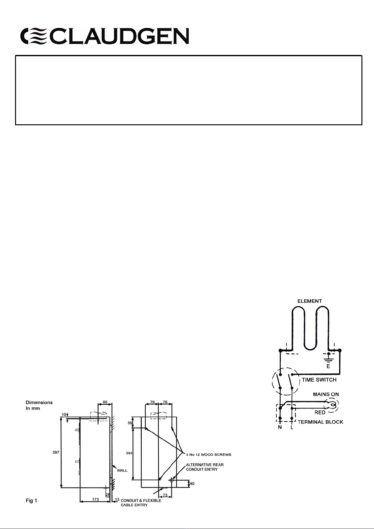
Dimensions of the fixing points are given in
Fig 1.
To allow the unit to be removed or to be
installed when the flue is already in position,
a clearance of 9.5 mm must be left between
the lower end of the flue and the top of the
incinerator so that the unit can be raised
sufficiently above its normal position to
allow the fixing screw heads to come out of
the keyhole slots in the fixing lugs.
Dimensions given in Fig 1 allow an
appropriate clearance between the bottom of
the flue and the top of the unit. To fix the
unit, insert the screws so that the heads are
about 6 mm from the wall. Suspend the unit
by means of lugs provided on the three wall
fixing screws. During this operation the flue
should be inserted into the socket of the
incinerator. When in position tighten the
screws firmly. When installed, the
incinerator will stand away from the wall
leaving a 13 mm gap. This gap must not be
obstructed as it is for ventilation purposes.
Single Flues
a) The incinerator should be sited in a
position which eliminates inclined flue
runs as far as possible.
b) The Sanfire 40 accepts 76.2 mm i.d. flue
piping, the first 600 mm of which we
recommend you use our HE6767
600 mm flue. From this, our flue
adaptor HE6768 should be used to
enable connection to a 3” (76 mm) flue.
The remaining lengths and accessories
should be in a light gauge aluminium or
fibre cement.
c) In changing direction use bends with a
minimum angle of 1200fitted with
cleaning doors. In straight runs, pipes
fitted with cleaning doors should be
provided as necessary for maintenance
purposes. Regular cleaning of flues is
essential.
d) To minimise the possibility of down
draughts, a vertical flue length of 2.7 m
or more is recommended.
e) The flue should be taken above the eaves
of the building or surrounding structures.
Externally the flue should be stood off
the wall to clear eaves or coping and, if
necessary, should be taken through such
a projection to avoid bends near the flue
termination. The installation should be
completed with a suitable cowl.
f) All flue connections should be carefully
sealed including the joint on the socket
of the incinerator.
g) Where a long inclined or any horizontal
flue run is unavoidable ask for details of
a suitable fan to assist ventilation.
Common Flues
Sanfire incinerators can be easily connected
to common flues and used in mechanically
ventilated toilets provided that forced
extraction is incorporated in the main stack.
For guidance on design, details of fittings
and fan requirements for common flues, ask
for Advisory Leaflet HLT/1041.
NB
When designing flue systems attention
should always be given to the relevant
British Standards and BS Codes of Practice
for Building and Flues, also to the Building
Regulations.
Electrical Connections
a) The Sanfire 40 is suitable for connecting
to a 220/240 volts single phase AC
supply (for other voltages, ask for
technical information).
b) The unit is rated 550 watts at 230 volts.
c) A separate 5 amp fuse must be provided
in the supply wiring to the unit.
d) An entry is provided at the rear of the
unit for connection of 20 mm conduit or
a small BESA box mounted in the wall
behind the unit. An alternative 20 mm
conduit entry and a cable clamp for
connection by flexible cable are also
provided in the base of the unit. These
positions are shown in Fig 1.
e) Connect the mains leads to the terminals
as shown in Fig 2.
OOMB 1227 Iss 02
f) Earthing. The earth terminal is adjacent
to the terminal block and is clearly
marked with the symbol . For safety
reasons, a sound earth connection MUST
ALWAYS be made for the unit before it
is put in use.
g) The unit should be wired to an adjacent
switch socket in accordance with IEE
Regulations for the Electrical Equipment
of Buildings.
Operation
Insert the towel by fully opening the door
flap at the top of the unit. This operation is
all that is required and automatically starts
the burning cycle. Do not fill above the
lower level of the door opening.
NOTE: The time switch will cut out 20
minutes after the door is closed but the
charge will continue to burn.
Maintenance
The ash drawer must not be allowed to
overfill. If the incinerator is in constant use
it should be emptied weekly or more often if
it should appear necessary.
ALWAYS ENSURE THAT THE MAIN
EXTERNAL ELECTRICITY SUPPLY IS
SWITCHED OFF BEFORE ATTENDING
TO SERVICING OF THE UNIT.
To replace the heating element Cat No:
HE6821
a) Dismantle the unit as described under
installation paras (a) to (d).
b) Remove the screws at the ends of the
element mounting plate, also the hinge
rod.
c) Disconnect the electrical connections.
d) The element complete with mounting
place can now be removed, lifting the
charging door to allow clearance.
e) Fit the new element to the mounting
plate and re-assemble in the reverse
order ensuring the element is located
between the element guard rods.
To replace the Element Guard
a) Remove the heating element as
previously described.
b) Pull the charging door forwards and
downwards, clear of the ash pan support
tray.
c) Spring front edges of the combustion
chamber outwards and slip the guard
rods out of locating holes. The element
guard can then be removed from the unit.
d) Replace the element guard and refit in
the reverse order.
To replace the time switch Cat No:
HE6854
a) Dismantle the unit as described under
installation paragraphs (a) to (d).
b) Detach the linkage mechanism by
releasing the screw fixing to the timer
shaft (item D Fig 3).
c) Remove the two timer fixing screws.
d) Disconnect the push-on connections,
remove and replace the timer.
e) Reassemble in the reverse order,
ensuring that the spacing bush is fitted
between the mounting plate and the
linkage. NB It is essential that the short
arm of the linkage engages with the ‘L’
section of Item D Fig 3 and that the link
is in the position shown when the timer
is in the ‘Off’ position.
Electrical Spares
Ref No Description Part No
(see Fig 3)
A Heating Element HE6821
B Time Switch HE6854
Spares
It is essential when ordering spares or
replacement parts to state ‘for HE6820
Sanfire 40 Sanitary Incinerator’ and to quote
the serial number of the incinerator. This
number is stamped on the rating plate.
SPECIAL NOTICE
This appliance is fitted with a sheathed wire
element and it is a feature of such an element
that a small amount of moisture can be
absorbed from the atmosphere during
storage, or even after installation if not in
regular use.
In certain cases, it is possible that moisture
may be absorbed to such a degree as to
decrease the earth leakage resistance such
that the appliance would cause spurious
operation of sensitive earth leakage cut-outs,
if these are fitted in the supply circuit.
Should such a condition occur, disconnect
the appliance from the circuit and operate for
a few minutes in a circuit without earth
leakage protection. This will normally drive
off the offending moisture and render the
appliance suitable for return to the circuit
with earth leakage protection. THIS
PROCEDURE MUST ONLY BE CARRIED
OUT BY A COMPETENT ELECTRICIAN.
Should any further difficulties be
encountered, Claudgen Technical
Department should be consulted.
In the interest of progress the Company reserves the right
to vary specifications from time to time without notice.
The material listed is offered subject to the Company’s
General Conditions of Sale, a copy of which may be
obtained u
p
on re
q
uest.

This manual suits for next models

1

Other Claudgen Heater manuals

Claudgen HE7230W Installation and operating instructions

Claudgen

Claudgen HE7230W Installation and operating instructions

Claudgen ScreenZone CA1309S10 User manual

Claudgen

Claudgen ScreenZone CA1309S10 User manual

Claudgen HE8320 Original operating instructions

Claudgen

Claudgen HE8320 Original operating instructions

Claudgen HE8515 Manual

Claudgen

Claudgen HE8515 Manual

Claudgen ScreenZone CA2015S User manual

Claudgen

Claudgen ScreenZone CA2015S User manual

Claudgen HE7402 Original operating instructions

Claudgen

Claudgen HE7402 Original operating instructions

Claudgen CA1509S Original operating instructions

Claudgen

Claudgen CA1509S Original operating instructions

Claudgen HE6502 Manual

Claudgen

Claudgen HE6502 Manual

Claudgen HE8320RF Manual

Claudgen

Claudgen HE8320RF Manual

Claudgen HE7010 Manual

Claudgen

Claudgen HE7010 Manual

Claudgen HE7237 User manual

Claudgen

Claudgen HE7237 User manual

Claudgen SCREENZONE RAC1306 User manual

Claudgen

Claudgen SCREENZONE RAC1306 User manual

Claudgen HE7402RF Manual

Claudgen

Claudgen HE7402RF Manual

Claudgen HE7237SL User manual

Claudgen

Claudgen HE7237SL User manual

Claudgen CH06CSi User manual

Claudgen

Claudgen CH06CSi User manual

Claudgen Heat-Zone Manual

Claudgen

Claudgen Heat-Zone Manual

Claudgen ScreenZone HE8409 User manual

Claudgen

Claudgen ScreenZone HE8409 User manual

Claudgen HE7010RF Manual

Claudgen

Claudgen HE7010RF Manual

Claudgen HE7230SL User manual

Claudgen

Claudgen HE7230SL User manual

Claudgen HE7230 User manual

Claudgen

Claudgen HE7230 User manual

Claudgen HE6137SL Use and maintenance manual

Claudgen

Claudgen HE6137SL Use and maintenance manual

Claudgen RCT250SL Use and maintenance manual

Claudgen

Claudgen RCT250SL Use and maintenance manual

Claudgen RAC1509 User manual

Claudgen

Claudgen RAC1509 User manual

Claudgen HE7402-31 Manual

Claudgen

Claudgen HE7402-31 Manual

Popular Heater manuals by other brands

Stelpro CW1000 Series user guide

Stelpro

Stelpro CW1000 Series user guide

ELECTRIMART 65012 manual

ELECTRIMART

ELECTRIMART 65012 manual

DAY Useful Everyday 73454 instruction manual

DAY Useful Everyday

DAY Useful Everyday 73454 instruction manual

Bimar S597.EU Instruction booklet

Bimar

Bimar S597.EU Instruction booklet

Pace PH 100 Operation manual

Pace

Pace PH 100 Operation manual

Dyna-Glo IR6PMDG-1 manual

Dyna-Glo

Dyna-Glo IR6PMDG-1 manual

Zass ZKG 01 W/B Service manual

Zass

Zass ZKG 01 W/B Service manual

DeLonghi TRDX4 manual

DeLonghi

DeLonghi TRDX4 manual

Adax VV13T s2 user manual

Adax

Adax VV13T s2 user manual

Sealey RD800 instructions

Sealey

Sealey RD800 instructions

Gemini GCH1800W instruction manual

Gemini

Gemini GCH1800W instruction manual

Stanley ST-40-GFA-E User's manual and operating instructions

Stanley

Stanley ST-40-GFA-E User's manual and operating instructions

Ridea Living Othello Mono Slim Instruction and installation booklet

Ridea

Ridea Living Othello Mono Slim Instruction and installation booklet

Hyundai HAL 100 instruction manual

Hyundai

Hyundai HAL 100 instruction manual

SKF TIH L Instructions for use

SKF

SKF TIH L Instructions for use

GSI Group 2000 Series Installation and operating instructions

GSI Group

GSI Group 2000 Series Installation and operating instructions

Clarke XR55 Operating & maintenance instructions

Clarke

Clarke XR55 Operating & maintenance instructions

Suntec Wellness KLIMATRONIC Heat Supreme 2000 manual

Suntec Wellness

Suntec Wellness KLIMATRONIC Heat Supreme 2000 manual

manuals.online logo
manuals.online logoBrands
  • About & Mission
  • Contact us
  • Privacy Policy
  • Terms and Conditions

Copyright 2025 Manuals.Online. All Rights Reserved.