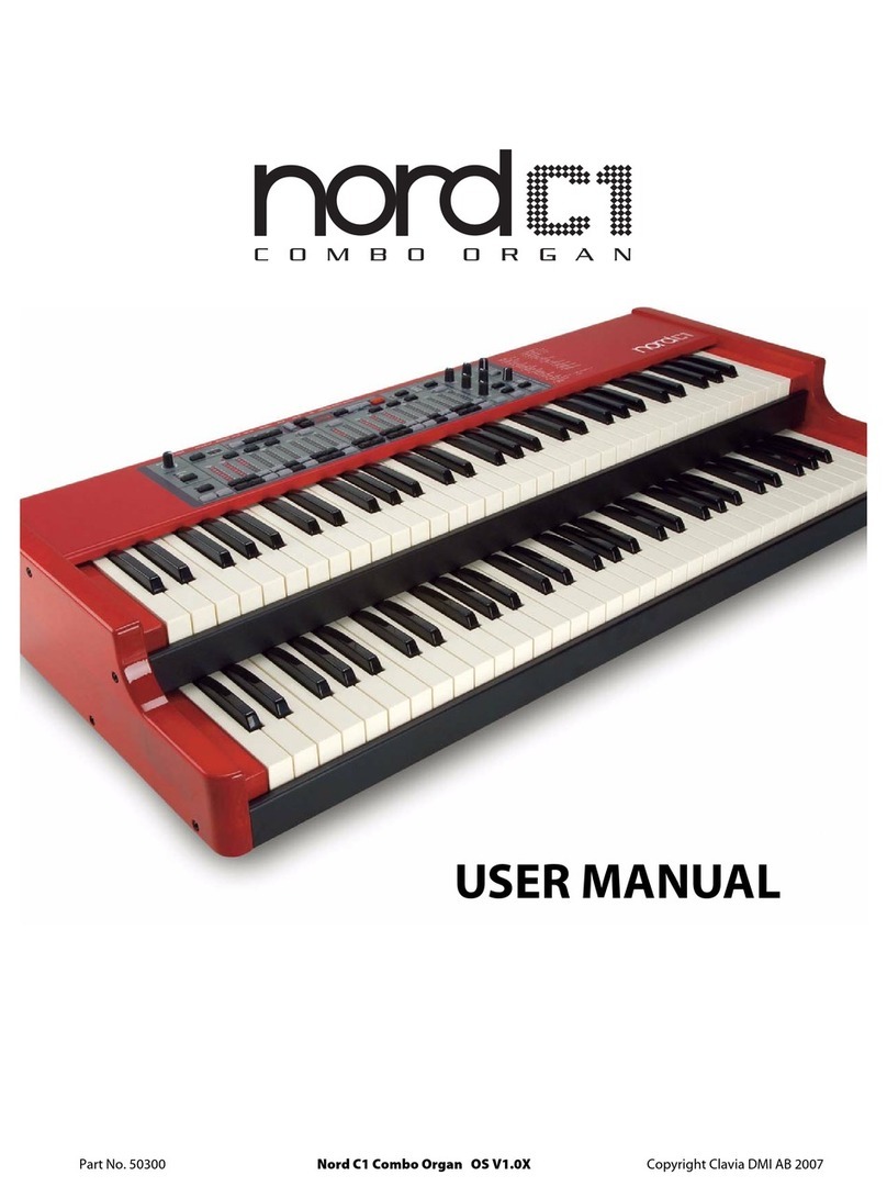
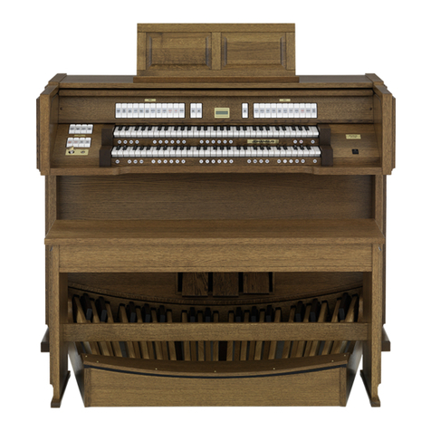
Clavia Nord C1 User manual

SERVICE MANUAL

Clavia DMI Service manual Nord C1 Combo Organ rev. 1.0 Page 1
Table of contents
Overview....................................................................................... 3
Test program................................................................................ 4
Running the test program ........................................................... 4
Error Codes ................................................................................ 6
Hardware ...................................................................................... 7
Hardware structure ..................................................................... 7
Opening the synth....................................................................... 8
Hardware versions.................................................................... 10
Software ..................................................................................... 10
Spare Parts................................................................................. 11

Clavia DMI Service manual Nord C1 Combo Organ rev. 1.0 Page 2
The Nord C1 Combo Organ Service manual is arranged to help our service centers in
the best way possible. However the Nord C1 Combo Organ user manual is a very useful
guide, use it as a reference in addition to this service manual. If you have access to
internet you’ll find the user manual available for download and also a lot of useful
information on our website www.clavia.se
I The information in this service manual is intended for service centers that repair
Clavia products. It may not be copied, reposted, modified, served from other web
pages, made into derivative works or distributed to other sources such as end users or
retailers that do not repair Clavia products.
I In this manual the Nord C1 Combo Organ will be referred to as Nord C1
h Important safety information
Dangerous voltage levels are present within the unit.
- Unit should be opened exclusively by qualified service personnel.
- Always disconnect the power supply cord before opening to avoid
electrical shock.
- Components and complete circuitboards may only be put into service when they
are securely fixed in the instrument casing.
- Take necessary precautions against ESD before opening the unit.
Revision history
rev. 1.0 - First release

Clavia DMI Service manual Nord C1 Combo Organ rev. 1.0 Page 3
Overview
Product line
The Nord C1 Combo Organ is available
In one version.
- 2 x 61 note Keyboard version
Internal memory
The internal sound memory of Nord C1 consists of 126 program locations.
In addition there are two live buffer memories.
Fuse ratings
Voltage 115 V 230 V
Fuse 300 mA 125 mA
Physical Dimensions
Nord C1
W: 950 mm / 37,4"
D: 445 mm / 11,3"
H: 163 mm / 6,4"
Weight: 15Kg / 33 lbs

Clavia DMI Service manual Nord C1 Combo Organ rev. 1.0 Page 4
Test program
Running the test program
The Nord C1 test program is stored both in Flash and in the BootPROM position U32.
Test program version is shown in the display when the test program is initiated.
In order to trace a hardware error easier, each Nord synthesizer has a test program.
This program is primarily used in production in order to test all functions.
The functions provided by the test program allow a quick and easy search for possible
errors on the hardware.
I
I I
I WARNING: Improper use of the test program or powering off the synth during a test
can result in malfunction of the synth. The test program may only be used by qualified
service personnel and is not intended for end users.
In order to execute the different tests on a Nord C1, press and hold buttons
[ Shift + Prog ] at power up. When test mode is entered a DRAM test is performed.
The DRAM test progress is indicated by the sub/sub3 and fund drawbar LED´s in the
lower manual section on the front panel. The LED´s are divided into three groups, where
each group of LED´s represents a part of the DRAM test procedure. During the DRAM
test the LED groups will light up, one by one. If errors are detected one of the three
groups will flash.
Navigating through the test program
- Press the designated button to enter a test group.
[ Prog ] [ Live 1 ] [ Live 2 ]
Mainboard test Panelboard test System menu
- Press [ Store ] to activate and to exit test.
- Press [ Prog/menu up ] or [ Prog/menu down ] to toggle between available tests.
- Press [ Panic ] to reset a test.

Clavia DMI Service manual Nord C1 Combo Organ rev. 1.0 Page 5
Available tests are:
[ prog ] Main board
1.bd Mainboard Performs test 4,5,7
2.Fn Final Only used in production
3.Ht Heat Only used in production
4.ds DSP Tests the two DSP´s, including external memory.
5.EP EEPROM Performs a quick test of the EEPROM.
6.EP. EEPROM Long Tests the entire EEPROM.
7.FL Flash Performs a quick test of the Flash circuits.
Flash data is not altered.
8.FL. Flash Long Tests the entire Flash memory area.
Flash data is not altered.
9.ni MIDI Tests MIDI communication. Connect a MIDI cable from MIDI in
to MIDI out and then to Bass Pedal MIDI.
Successful test is presented as O__O
A.yb Keyboard Press one key at a time. Test counts number of keys pressed.
Upper and lower switch is indicated by the dots in the display
b.Pd Pedal Tests the function of the pedal inputs.
To fully test the Rotor control a half moon switch must be used.
Sustain Rotor Swell
P pressed F fast C connected
r released S slow
C.LE Leslie Only used in production
d.AU Audio Only used in production
[ Live 1 ] Panel board
1.Pn Panelboard Performs test 2-3
2.bt Button Tests the function of all the buttons
3.Ad ADC Tests the function of the A/D converter on the panel board.
Knobs incl. swell pedal
[ Live 2 ] System
1.Sn Serial no. Read the serial no. by pressing [on] - [soft] - [fast] - [third]
buttons in the percussion section of the panel board.
2.CS Checksum Only used in production
3.EF Erase Flash Will set all data in Flash to “1”
4.CL Clear EEPROM Will set all data in EEPROM to “0”

Clavia DMI Service manual Nord C1 Combo Organ rev. 1.0 Page 6
Error Codes
BootPROM ERRORS:
Nord C1 Boot Program v0.02 Error Codes
0 : Boot error - Flash error (unable to identify flash)
1 : Boot error - Flash is empty
2 : Boot error - Flash error (access failure)
3 : Boot error - Invalid OS in flash
4 : Boot error - Invalid test-program in flash
5 : Boot error - Invalid program (reserved 1) in flash
6 : Boot error - Invalid program (reserved 2) in flash
7 : Boot error - Invalid test-program in PROM
8 : Boot error - Invalid flash data (CAB-header is corrupt)
9 : Boot error - Internal error
10 : Transfer error - Checksum error
11 : Transfer error - Underrun error
12 : Transfer error - Overrun error
13 : Transfer error - Invalid memory type
14 : Transfer error - Invalid memory id
15 : Transfer error - Flash write failure
16 : Transfer error - Flash erase failure
17 : Transfer error - Flash read failure
I
I I
I NOTE
When an error is detected within the test program it will be presented either as
“Err”
Or by the corresponding chip id flashing in the display, e.g
“U9”

Clavia DMI Service manual Nord C1 Combo Organ rev. 1.0 Page 7
Hardware
Hardware structure
The hardware structure consists of:
One power supply unit, one main board and one panel board.
Power supply
The Nord C1 is supplied with several different voltages from the power board.
These are +3.3V, +5V and ±12V. For more information on where to measure these
voltages, see the schematic for the power supply. There are also three voltages
supplied from the main board. U12 (23340) supplies the Host and DSP´s with +1.8V,
U14 (21540) supplies the audio D/A with +5V and U37 (25820) wich supplies the high level
output with +30V. The Power supply is connected to the main board with a 10 pole
connector P2 (22480).
Main Board
The main board is equipped with two DSP´s U8-U9 (23280),which is controlled by a host
processor U7 (23180) with one DRAM circuits U4 (23170) (1M*16 bits).
Boot code for the host processor is stored in the BootPROM U32 (23892) (512k*8 bits).
OS is stored in a FLASH memory U33 (23420) (512k*8 bits).
Various other information, e.g. user settings is stored in an EEPROM U17 (24147)
Audio D/A conversion is performed by U21 (23430).
A/D conversion of the control pedal takes place on the panel board U23 (23370).
All output jacks are filtered from radio signals with an EMI-filter (23110)
(component designator prefix F). External connectors are one 26 pole connector for the
panel board P5 (22520),a 10 pole connector for the power supply unit P6 (22480),
a 10 pole straight connector P8 (25551) for the 11 pin Leslie connector and four keyboard
connectors P1-P4 (22670).
Panel Board
On the panel board you will find all control functions of the Nord C1. This panel also
holds the LED (3x20780), the panel board is connected to the main board with a 26 pole
connector P1 (22520).

Clavia DMI Service manual Nord C1 Combo Organ rev. 1.0 Page 8
Opening the synth
WARNING: Take necessary precautions against ESD before opening the synth.
Disassembly Nord C1
1. Remove the 4 screws (40290) holding the panel to the wood gables.
2. Remove the 6 screws (40018).
3. Lift of the upper lid (40273).
4. Disconnect the 26 pole ribbon cable (23830) to the mainboard.
Removing the Panelboard
1. Pull off the knobs (22900).
2. Disconnect the 26 pole ribbon cable (23830).
3. Remove the 12 screws (40262) holding the panelboard.

Clavia DMI Service manual Nord C1 Combo Organ rev. 1.0 Page 9
WARNING: Take necessary precautions against ESD before opening the synth.
Removing the Powerboard
1. Remove the 6 screws (40262) holding the Powernoard to the Lower lid.
2. Remove the 2 screws (40013) next to the AC socket.
3. Disconnect the 10 pole ribbon cable (23880).
Removing the Mainboard
1. Remove the 3 screws (40262) holding the mainboard to the lower lid.
2. Remove the 7 nuts and washers holding the ¼” jacks.
3. Remove the 6 screws (40010) holding the MIDI connectors.
4. Disconnect the 26 pole ribbon cable (23830) to the panelboard.
5. Disconnect the 10 pole ribbon cable (23880) to the powerboard.
6. Disconnect the 10 pole rotary spkr cable (22093).
7. Disconnect the 4 keyboard cables (P1-P2 22290 P3-P4 24100)

Clavia DMI Service manual Nord C1 Combo Organ rev. 1.0 Page 10
Hardware versions
Main board BootPROM Notes
ver. 1.0 V1.0-xx “xx” defines BootPROM version
Hw version is shown in the LED when you turn on the unit.
I
II
I Important notes
-The latest available OS version will work on all officially released main board versions,
however old OS versions might NOT work on newer main boards.
Always use the latest OS version!
Software
Uploading OS and sounds
The operating system is stored in a FLASH circuit on the main board.
OS and sounds are uploaded via USB.
For more information on how to update the OS Visit
www.clavia.se there you can find the latest Software packages.
Current OS version is shown in the display when you power on the unit.

Clavia DMI Service manual Nord C1 Combo Organ rev. 1.0 Page 11
Spare Parts
Mechanics:
Pos Part no.
Item qty
1 40004
Keyboard 5 Oct. NE61 2
2 23830
Ribbon cable 26pol* 1
3 23880
Ribbon cable 10pol*140 1
4 22290
Keyboard cable 2
5 24100
Keyboard cable 2
6 40242
spacer screw M4x10 2
7 40010
Screw, midi 6
8 40013
Screw, AC input 2
9 40039
Screw, keyboard E61/E73 24
10 40018
Screw, upper/lower lid 12
11 40262
Screw M4x6 25
12 40290
Screw, Organ gable 12
13 40038
Screw M4x12, Leslie/bumper 6
14 40068
Pop rivet 3,2x8 4
15 40297
Rubber foot 21mm 4
16 22900
Knob D-form with grey line 8
17 40081
Display window, red N3/N2X 1
18 20850
LED lens shield 6, N3/NE 1
19 40057
Nut M4 14
20 40273
Upper lid NC1O 1
21 40274
Lower lid NC1O 1
22 40275
Distance plate NC1O 1
23 40276
Angle bracket, support NC1O 1
24 40298
Angle bracket NC1O, short 1
25 40239
U-channel 2
26 40299
U-channel NC1O, long 1
27 40280
Wood panel NC1O, left 1
28 40281
Wood panel NC1O, right 1
29 50288
Bumper, Nord Stage 2
30 22093
Cable Rotary spkr complete 1
Panelboard:
Pos Part no.
Item qty
31 60112
Panelboard NC1O 1
32 20980
100uF/16V 6,3x6,0 Ellyt SMD 1
33 20960
10uF/35V 5,0x6,0 Ellyt SMD 5
34 20720
Diod Bav 56 sot23 38
35 20700
Diod Bav70 Sot23 1
36 21950
Transistor BCX53 Sot89 PNP 12
37 23310
74HCT374 TSSOP 8
38 25600
74LCX00 TSSOP 1
39 25605
74LCX32 TSSOP 1
40 25608
74LCX245 TSSOP 1
41 25606
74LCX138 TSSOP 1
42 21930
74HC245 TSSOP 1
43 23370
MAX1039AEEE 1
44 21480
OP amp LF353D So 8 1
45 20870
LED lens straight, NE 20
46 20840
LED lens 6, N3/NE 1
47 20860
LED lens single 39
48 20780
LED Eight 3
49 22520
Connector 26 pole 1
50 22030
Button black Nord/ddrum 44
51 22050
Button grey NE 29
52 22040
Button red Nord 1
53 20640
Pot.10kA Lin. Nord 8

Clavia DMI Service manual Nord C1 Combo Organ rev. 1.0 Page 12
Mainboard:
Pos Part no.
Item qty
54 60110
Mainboard NC1O 1
55 20980
100uF/16V 6,3x6,0 Ellyt SMD 7
56 20960
10uF/35V 5,0x6,0 Ellyt SMD 7
57 20940
1uF/35V 4,0x5,5 Ellyt SMD 6
58 25500
4.7u ker X7R 50v 1210 Murata 2
59 25305
Diod S1G SMA 7
60 20700
Diod Bav70 Sot23 6
61 25310
Diod S1G SMA Schottky 1
62 23110
EMI-Filter 2,2nF,+50/-20% 100V 17
63 23100
EMI-Filter 470pF,+50/-20% 100V 9
64 25380
Chipdrossel Koa 10uH LPC4045 1
65 21960
Transistor BCX54 Sot89 NPN 5
66 21950
Transistor BCX53 Sot89 PNP 2
67 21970
Transistor BC847B Sot23 NPN 2
68 21980
Transistor BC857B Sot23 PNP 1
69 25290
Relay 2-pol 3
70 21520
Op amp LM833M 2
71 25608
74LCX245 TSSOP 8
72 23170
Dram 16Mbit 1
73 23160
Sram NMG2/NS 4MB 1
74 23180
Host NMG2/NS 1
75 23280
DSP NMG2/NS 2
76 23340
Regulatorv1,8v yt 1
77 21940
74HC374 TSSOP 2
78 21540
Regulator 5,0 1
79 24147
EEprom NS 1
80 25604
74LCX14 TSSOP 2
81 21810
74HC32 So14 3
82 23430
Dac N2X/NMG2/NS 1
83 25850
Op amp dual so8 2
84 21570
PC 400TSo 2
85 23200
Resetcircuit NMG2/NS 1
86 23420
Flash 1
87 23730
Socket, otp 1
88 23892
BootPROM NC1O, Programmed 1
89 23190
USB circuit NMG2/NS 1
90 25820
Regulator step-up 1
91 25351
Crystal oscillator 16,6666 MHz 1
92 23270
Crystal oscillator 56,620363 Mhz 1
93 23060
crystal 6 Mhz SMD 1
Mainboard:
Pos Part no.
Item qty
94 22610
Connector 1/4" Stereo/switch 3
95 22600
Connector 1/4" Stereo 1
96 22590
Connector 1/4" Mono 3
97 22640
Connector din 5pol Midi 3
98 22690
USB connector Type B 1
99 22670
Connector 16 pole, micromatch 4
100 22520
Connector 26 pole 1
101 22480
Connector 10pol 1
102 25551
Connector 10pol, straight 1
Powerboard:
Pos Part no.
Item qty
103 60183
Power board NMG2 1
104 20960
10uF/35V 5,0x6,0 Ellyt SMD 3
105 23590
Diod ES3AD SMC 6
106 23900
Diod SS34 Schottky 1
107 23600
Effect drossel 1
108 23610
Regulator +5,0 Yt 1
109 23620
Regulator +3,3 Yt 1
110 23630
Regulator +12 Yt 1
111 23640
Regulator -12V Yt 1
112 20910
Capacitor 4700pF X2 2
113 23560
1000u/35V Nichicon 3
114 23800
470u/50V 1
115 22840
Fuse house nord/dd4/mod 1
116 23120
Drossel RN112-0,8/02 1
117 22620
Socket AC N3/NE 1
118 22480
Connector 10pol 1
119 22000
Powerswitch On/off 1
120 22020
Button grey power on/off 1
121 22630
AC-Switch 1
123 22770
Trafo NMG2/NS 1
124 40017
Screw, transformer 4
125 40176
Plastic isolator 1
126 23960
220uF/25V Ellyt axiell 1
127 40180
Spacer 2mm Nylon 2
Other manuals for Nord C1
1
Table of contents
Other Clavia Musical Instrument manuals

Clavia
Clavia Nord Piano 2 HA88 User manual

Clavia
Clavia Nord Electro Seventy Three User manual

Clavia
Clavia Nord C2 User manual

Clavia
Clavia nord piano 5 User manual

Clavia
Clavia Nord Electro 5D 61 User manual

Clavia
Clavia Nord C1 User manual

Clavia
Clavia Nord Piano 88 User manual

Clavia
Clavia Nord Electro 4HP User manual

Clavia
Clavia NORD PIANO 3 User manual

Clavia
Clavia Nord Piano 2 HP User manual