Clayton Tent & Vent TV-1400 Guide

January 2021
WARNING
SAFETY LEGEND
• The proper NESHAP Filters from Clayton Associates must be installed in the TV-1400 at all times
• The TV-1400 must be used with the supplied or recommended accessories from Clayton Associates
• Any alteration to the TV-1400 by a third party will nullify its warranty
• Always lock the brakes on the TV-1400 once positioned so that it does not roll
WARNING
Hearing protection is recommended when
operating this equipment.
Respiratory protection is recommended when
operating this equipment.
Read and understand operator’s manual before
using this equipment.
Eye protection is required when operating
this equipment.
WARNING WARNING
WARNING
WARNING
Scan this QR code for
online instructions and
documentation, or visit
www.ClaytonHowTo.com
Safety – Operation – Maintenance
Keep this document in a safe place
Read and understand this manual before operating your air tool
Tent & Vent
High Flow NESHAP Filtration System
Model: TV-1400
Designed for the collection of wet paint overspray containing Hexavalent Chromium or other heavy metals

Table of Contents ...............................................................................................................2
Applications & Environments .............................................................................................3
What’s Included..................................................................................................................4
Getting Started ...................................................................................................................5
Before Each Use ................................................................................................................6
Maintenance.....................................................................................................................10
Accessories......................................................................................................................13
TABLE OF CONTENTS
Repair or Warranty Contact Clayton Associates, Inc. •1650 Oak Street •Lakewood, New Jersey 08701 •P.+1-732-363-2100 F.+1-732-364-6084
www.DustlessMadeSimple.com
Page 2

APPLICATIONS & ENVIRONMENTS
The TV-1400 is designed to extract and lter wet paint overspray from enclosures or tents during painting operations where the
removal of overspray particulate, especially chromates, must adhere to the NESHAP Test Method 319 for Aerospace painting and
de-painting operations.
The TV-1400 employs a specic set of Clayton lters that when used together provide ltration that passes the NESHAP Test
Method 319 for both liquid and solid phase particulate.
ONLY APPROVED CLAYTON FILTERS SHOULD BE USED.
Grounding Instructions
The TV-1400 should be connected to an earth ground source with a Grounding/Bonding Cable. If the TV-1400 should come in contact
with an external electrical source, grounding provides a path of least resistance for electrical current to reduce the risk of electrical shock.
Bonding Instructions
The work piece should be bonded to the same earth ground as the TV-1400. This ensures that the TV-1400 and the work piece are at the
same electrical potential to eliminate static discharge between them.
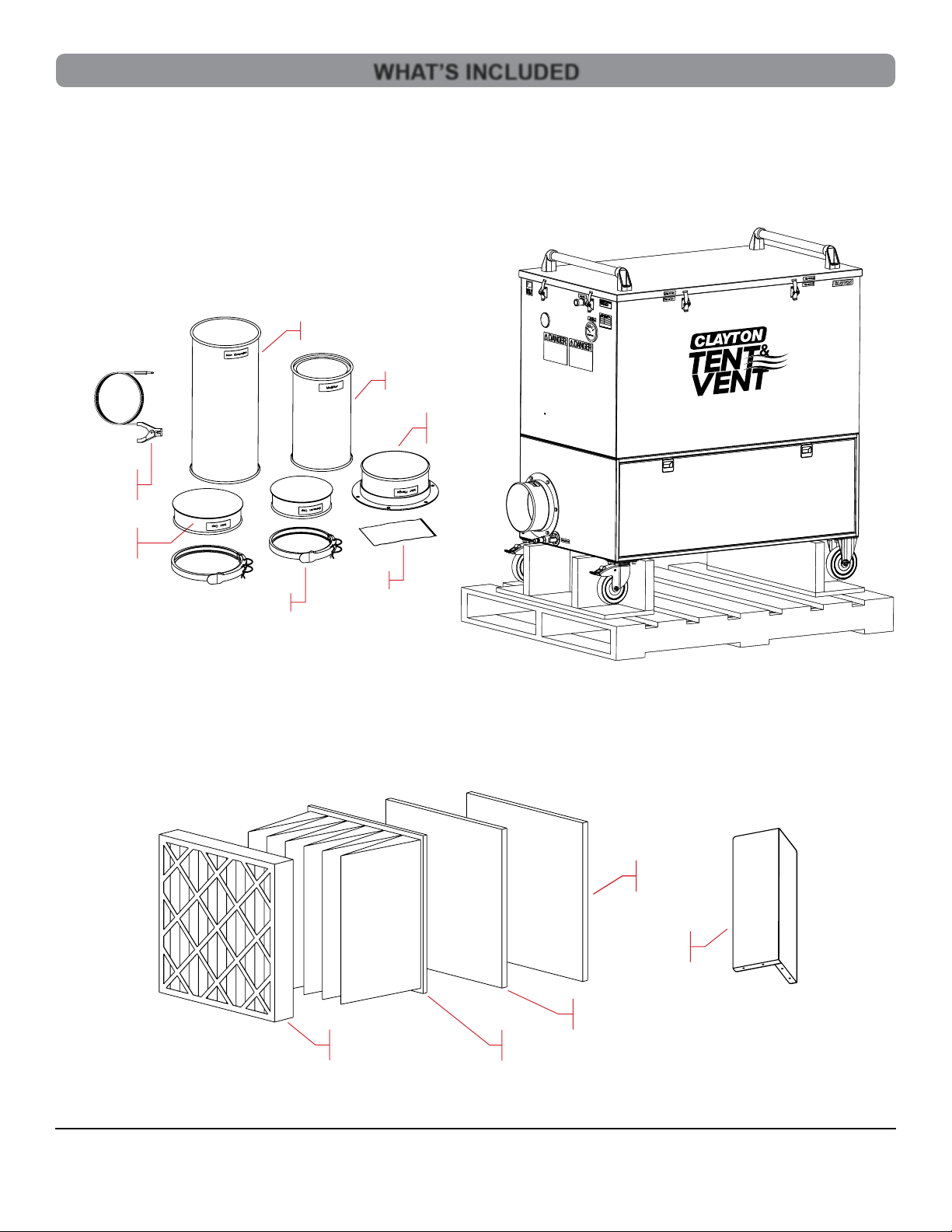
Tools And Attachments
The TV-1400 is only NESHAP compliant when used with the proper lters and accessories provided by Clayton. Proper order and
orientation of the lters is required. Any alteration to this equipment by a third party will nullify its warranty.
Compressed Air Requirements
• Compressed air must be clean, dry and oil free to prevent blockage of the pneumatic system
• Compressed airline and ttings must have a minimum diameter of 1/2in
• Compressed air supply must provide at least 90 psi
• Compressed air supply must provide a minimum of 50 cfm
WARNING
Repair or Warranty Contact Clayton Associates, Inc. •1650 Oak Street •Lakewood, New Jersey 08701 •P.+1-732-363-2100 F.+1-732-364-6084
www.DustlessMadeSimple.com
Page 3

Ground
Cable
Inlet Cap &
Clamp
Repair or Warranty Contact Clayton Associates, Inc. •1650 Oak Street •Lakewood, New Jersey 08701 •P.+1-732-363-2100 F.+1-732-364-6084
www.DustlessMadeSimple.com
Page 4
WHAT’S INCLUDED
Mufer
Inlet Extension
The TV-1400 ships with the following items in the lower drawer:
• TV-1400 Filter Unit
• 1 x Inlet Cap & Clamp
• 1 x Exhaust Cap & Clamp
• 1 x Mufer 12in
• 1 x Inlet Extension 18in
• 1 x NESHAP Stage 1 Filter
• 1 x NESHAP Stage 2 Filter
• 1 x NESHAP Multi-Pocket Filter
• 1 x Carbon Filter
• 1 x Inlet Flange and Hardware
Use only the following Clayton consumables:
• 627-242401-PM08 Stage 1 Filter
• 627-242401-PN99 Stage 2 Filter
• 627-242415-PM14 Multi-Pocket Filter
• 627-242404PC-02 Carbon Filter
• TV-1400-4 Inlet Diverter
Inlet
Flange
Carbon
Filter
Pocket
Filter
Inlet
Diverter
Stage 1
Filter
Stage 1
Filter
Stage 2
Filter
Hardware
Exhaust Cap & Clamp

Repair or Warranty Contact Clayton Associates, Inc. •1650 Oak Street •Lakewood, New Jersey 08701 •P.+1-732-363-2100 F.+1-732-364-6084
www.DustlessMadeSimple.com
Page 5
Repair or Warranty Contact Clayton Associates, Inc. •1650 Oak Street •Lakewood, New Jersey 08701 •P.+1-732-363-2100 F.+1-732-364-6084
www.DustlessMadeSimple.com
GETTING STARTED
Inlet Cover
Bolts
Washer & Nut
1. Using a forklift, remove TV-1400 from the shipping pallet
3. Attach the Inlet Flange – This may ship installed
• Using the 6 bolts and nuts provided attach the inlet ange
to the inlet opening
2. Identify and inventory all Items shipped in the lower drawer
• Refer to What’s Included on the previous page
4. Attach the inlet cover to the inlet ange
• Using the 8in band clamp provided, attach the inlet
cover to the upper inlet ange
Inlet Flange
Place forks
here to lift

Repair or Warranty Contact Clayton Associates, Inc. •1650 Oak Street •Lakewood, New Jersey 08701 •P.+1-732-363-2100 F.+1-732-364-6084
www.DustlessMadeSimple.com
Page 6
GETTING STARTED (CONT.)
BEFORE EACH USE
Exhaust Flange
Exhaust Cover
Mufer
Inlet Flange
5. Attach the exhaust cover
• Using the 7in band clamp provided, attach the exhaust
cover to the lower exhaust ange
Preparing the Unit for Use
Always engage the wheel brakes once in position so that the unit does not roll.
1. Attach the mufer to the lower exhaust
• Remove the exhaust cap from the lower exhaust ange and
store in the drawer
• Use the 7in band clamp from the cap to attach the 12in mufer
to the lower exhaust ange
2. Attach the Inlet Extension to the Inlet Flange (optional)
• Remove the exhaust cap from the upper inlet ange
and store in the drawer
• Use the 8in band clamp from the cap to attach
the 18in inlet extension to the upper inlet ange
Inlet Extension
Exhaust Flange

Repair or Warranty Contact Clayton Associates, Inc. •1650 Oak Street •Lakewood, New Jersey 08701 •P.+1-732-363-2100 F.+1-732-364-6084
www.DustlessMadeSimple.com
Page 7
BEFORE EACH USE (CONT.)
3. Attach the Flexible Ducting to the Inlet Flange (optional)
• Remove the exhaust cap from the upper inlet ange and store in the drawer
• Use the 8in band clamp from the cap to attach the 15ft inlet Flexible Ducting to the upper inlet ange
• Attach additional 15ft sections as needed, 3 max
4. Attach the Grounding Cable
• Plug a Grounding Cable into the Grounding Port next to the lower exhaust ange
• Clamp to either the work piece or the same grounding point as the work piece
Inlet Flange
Grounding Jack
Flexible Ducting
Grounding Cable

Repair or Warranty Contact Clayton Associates, Inc. •1650 Oak Street •Lakewood, New Jersey 08701 •P.+1-732-363-2100 F.+1-732-364-6084
www.DustlessMadeSimple.com
Page 8
BEFORE EACH USE (CONT.)
5. Attach the Compressed Air Line
• Ensure that the TV-1400 compressed air valve is in the OFF position
• Connect the compressed air line to a compressed air source
• Connect the compressed air line coupler to the compressed air plug on the TV-1400
• Compressed air must be clean, dry and oil free to prevent blockage of the pneumatic system
• Compressed airline and ttings must have a minimum diameter of 1/2in
• Compressed air supply must provide at least 90 psi
• Compressed air supply must provide a minimum of 50 cfm
6. Check the Filters
• Turn the compressed air valve to the ON position to activate the TV-1400
• Check the differential pressure gauge to determine if lter(s) need to be replaced
• If the Differential pressure gauge exceeds the maximum level specied then one or more of the lters need to be replaced
• Turn the compressed air valve to the OFF position to deactivate the TV-1400
• See the Replacing Filters section
Compressed
Air Plug
Differential
Pressure Gauge
Compressed
Air Valve
Compressed
Air Coupler

Repair or Warranty Contact Clayton Associates, Inc. •1650 Oak Street •Lakewood, New Jersey 08701 •P.+1-732-363-2100 F.+1-732-364-6084
www.DustlessMadeSimple.com
Page 9
BEFORE EACH USE (CONT.)
7. Attach to tent or area to be vented
• Insert the Inlet Extension or Duct Extension into the area to be vented and seal with masking tape or similar
• Ensure the area to be vented has an adequate air supply opening for make up air
8. Attach exhaust plenum (optional)
• Insert the end of the exhaust mufer into exhaust plenum and seal with Zip Tie or Masking Tape
9. Activating the TV-1400
• Full ow on this TV-1400 is 1200 cfm
• When activating the TV-1400, turn the compressed air valve on slowly so that the ow does not collapse the tent
• Turn the compressed air valve to the ON position to activate the TV-1400
Zip Tie or
Masking Tape
Tent
Exhaust Mufer
Exhaust Plenum
Inlet Extension
Masking Tape
Compressed
Air Plug

Repair or Warranty Contact Clayton Associates, Inc. •1650 Oak Street •Lakewood, New Jersey 08701 •P.+1-732-363-2100 F.+1-732-364-6084
www.DustlessMadeSimple.com
Page 10
MAINTENANCE
Changing the Inlet Bafe
The inlet bafe can accumulate a thick layer of paint overspray. It is removable to be cleaned or replaced.
1. Remove the inlet bafe
• Carefully remove the 4 nuts securing the bafe to the bottom of the lter compartment
• The threaded PEM studs are part of the lter compartment and NOT removable
• Carefully pry the bafe off the PEM studs - Residual paint may make removing the bafe difcult
2. Install a new or cleaned bafe
• Set the bafe over the PEM studs in the lter compartment
• Apply a small amount of anti-seize to the threads of the PEM studs
• Thread new or existing 10-32 lock nuts onto the PEM studs
• DO NOT OVERTIGHTEN
PEM Studs
Nuts
Bafe

Repair or Warranty Contact Clayton Associates, Inc. •1650 Oak Street •Lakewood, New Jersey 08701 •P.+1-732-363-2100 F.+1-732-364-6084
www.DustlessMadeSimple.com
Page 11
MAINTENANCE (CONT.)
Changing the Filters
Each lter has a Part No Label and a Flow Direction
1. Stage 1 Filter (627-242401-PM08)
• Non-woven mesh with internal wire frame
• Oriented with Air Exit Label on Air Exit side of TV-1400
• Ensure top corners are folded in before placing lid on the unit
2. Stage 2 Filter (627-242401-PN99)
• Non-woven mesh with internal wire frame
• Oriented with Air Exit Label on Air Exit side of TV-1400
• Ensure top corners are folded in before placing lid on the unit
3. Pocket Filter (627-242415-PM14)
• Oriented with Pockets on Air Exit side of TV-1400
• Ensure Pockets are not caught under lter frame
4. Carbon Filter (627-242404PC-02)
• Oriented with Flow Arrows pointing
to Air Exit side of TV-1400
Top Corner
Flow Direction Label
Filter Part No
Stage 2 Filter
Stage 1 Filter
Pocket Filter
Carbon Filter
Air Exit Side

Repair or Warranty Contact Clayton Associates, Inc. •1650 Oak Street •Lakewood, New Jersey 08701 •P.+1-732-363-2100 F.+1-732-364-6084
www.DustlessMadeSimple.com
Page 12
MAINTENANCE (CONT.)
5. Inspecting the Filters
• Ensure that the TV-1400 compressed air valve is in the OFF position
• Unlatch the cover of the TV-1400 (8 latches)
• Standing in front of the unit, grasp each black handle and lift the cover straight up
• Carefully place the cover in a safe location
• Visually inspect each lter starting with the Stage 1 lter
• Identify the rst lter that appears restricted or damaged and replace it
• Replace the cover and latch
• Repeat the Check Filter Procedure until the Differential Pressure Gauge reads below the maximum level specied
Note:
If the top and bottom of the Stage 1 Filter appear to be unused, you may rotate the Stage 1 Filter 90˚ and reuse,
before replacing, to extend lter life.

Flexible Ducting
Cart
Flexible Duct
Repair or Warranty Contact Clayton Associates, Inc. •1650 Oak Street •Lakewood, New Jersey 08701 •P.+1-732-363-2100 F.+1-732-364-6084
www.DustlessMadeSimple.com
Page 13
Use only the following Clayton accessories:
• 671-VHD80-15 Flexible Duct - 15ft with Clamp
• Flexible ducting provides the ability to direct Tent & Vent suction
to areas like aircraft tails
• Link up to 4 sections creating a 60 feet extension duct
• 955-TVC5225 Ducting Cart
• The Ducting Cart provides storage for 4 sections of exible ducting
• TV-1400-KIT2 Tent & Vent consumable replenishment kit
• Rosin Paper – Keeps your oor clean during painting in the tent
• Poly sheeting 4 mil – Create your tent from this durable poly sheeting
• High Tack Masking Tape – Use to attach the tent to the aircraft of whatever your work piece is
• Plier Stapler – Stitching poly sheeting together with staples is easier than tape
• Intake Filter Media – Use this gauze type material to cover make up air vents in your tent preventing debris from entering
• Poly Ducting – Attach to the Tent & Vent mufer to direct exhaust away from the work area or outside
• Filters – A compliment of Tent & Vent replacement lters
ACCESSORIES
Carbon
Filter
Intake Filter
Media
Pocket
Filter
Stage 2
Filter
Poly
Ducting
Plier
Stapler
Rosin
Paper
Poly Sheeting
4 Mil
High Tack
Masking Tape
Stage 1
Filter

Clayton products are proudly made in the USA
Repair or Warranty Contact Clayton Associates, Inc. •1650 Oak Street •Lakewood, New Jersey 08701 •P.+1-732-363-2100 F.+1-732-364-6084
www.DustlessMadeSimple.com
Other manuals for Tent & Vent TV-1400
1
Table of contents
Other Clayton Water Filtration System manuals
Popular Water Filtration System manuals by other brands

Allied Motion
Allied Motion TCI HarmonicShield Series Installation, operation and maintenance manual

Pall
Pall UT279 Series Service instructions

RainFlo
RainFlo RF4 Series Operation & installation instructions

Omnifilter
Omnifilter QK1 owner's manual

SuperFish
SuperFish 3000-6000-12000 user manual

GRE
GRE CFS20 instruction manual