Repair or Warranty Contact Clayton Associates, Inc. • 1650 Oak Street • Lakewood, New Jersey 08701 • P.+1-732-363-2100 F.+1-732-364-6084
Page 9
5.
•
•
–If it is not, turn it clockwise until it comes in contact with the underside of the power head.
6. Replace the primary power head.
• Carefully position the primary power’s head on the primary tank.
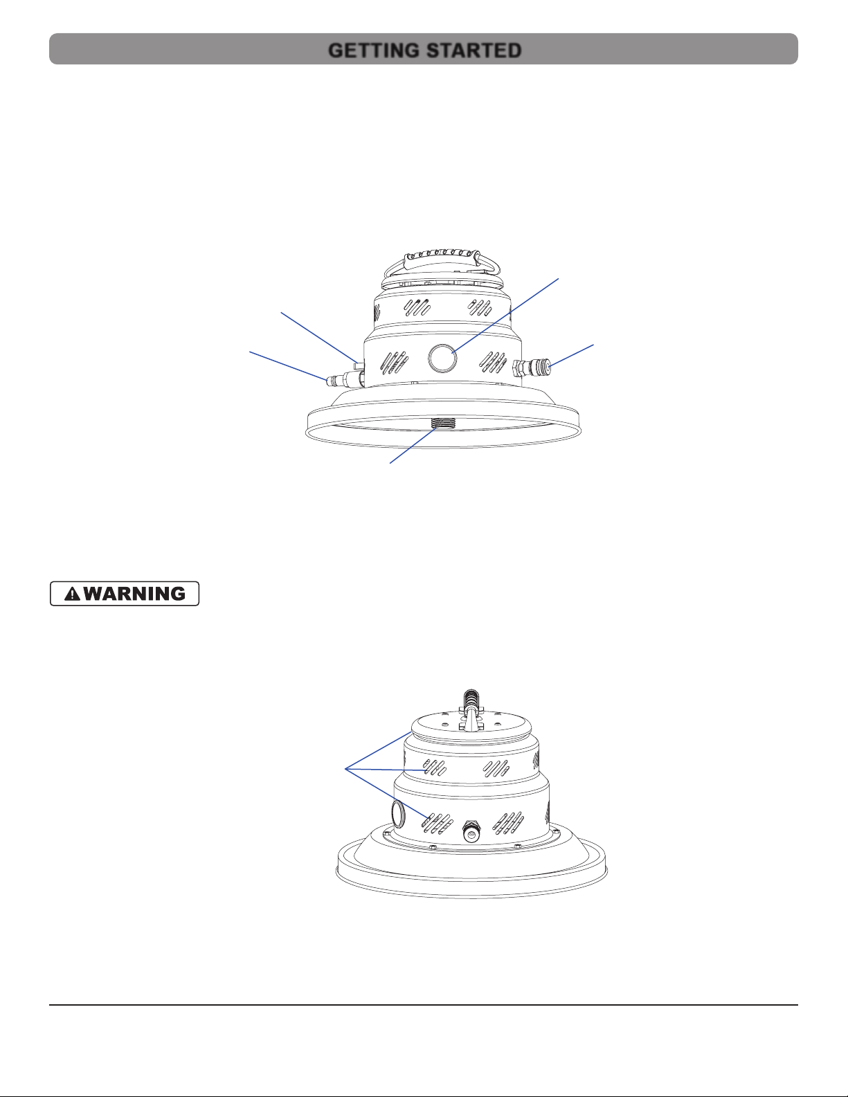
• Rotate the primary vacuum’s Compressed Air Control valve to the OFF position.
• Rotate the power head until the Compressed Air Control valve is aligned with the inlet port on the vacuum tank.
• Latch the power head to the tank.
• Rotate the support vacuum’s Compressed Air Control valve to the OFF position.
7. Disconnect the vacuums.
• Disconnect the SFC hose from the primary vacuum’s SFC port.
• Disconnect the SFC hose from the support vacuum’s inlet port.
I
1. Safe the vacuum.
• Disconnect the vacuum from the power source.
• Remove all hoses from the vacuum.
2. Remove the power head.
• Unlatch the power head from the tank.
•
•
3.
•
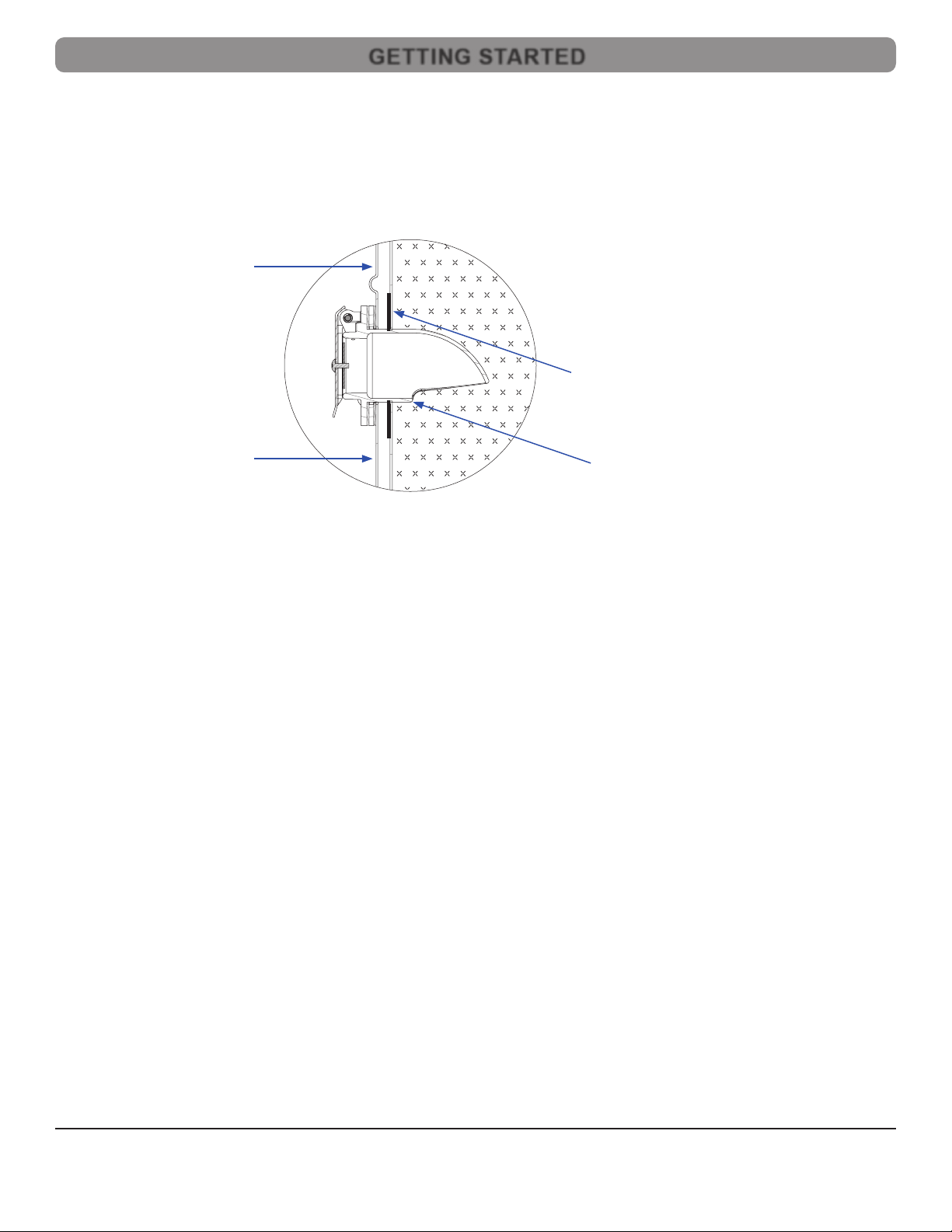
• Find the seam and carefully peel the Velcro apart.
•
4.
•
•
•
5.
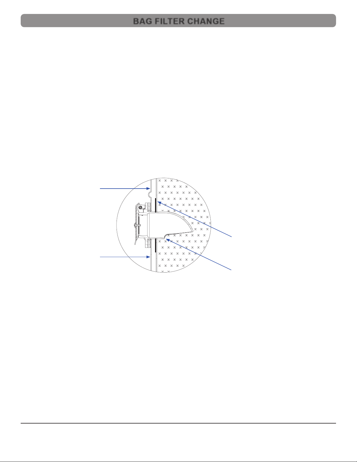
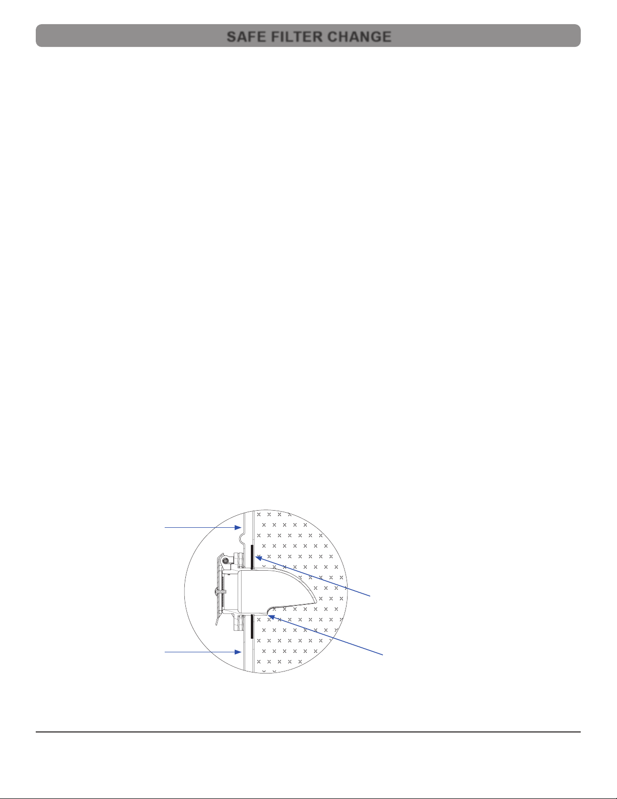
• Holding the power head on its side, examine the HEPA Filter.
•
–If it is not, rotate it clockwise until fully seated.
6. Replace the power head.
• Position the power head on the vacuum tank.
• Rotate the power head so that the Compressed Air Control valve on the power head is aligned with the inlet port on the vacuum tank.
• Latch the power head to the tank.
SAFE FILTER CHANGE
PRE-FILTER CHANGE