Clean World Distribution, Inc. Rhino-Mat RHM-CS User manual


2
OPERATIONS MANUAL
3
RHINO-MAT
Weight: 500 lbs.
Height: 50 inch
Width: 40 inch
Depth: 26 inch
Power: 110V/60 (30 Amps
Required)
Watt: 3,000 watts
Speed: 2 mat per minute
Mat size: Up to 2.6 feet wide
Available outer construction:
RHM-CS Carbon Steel w/powder
coat recommended for enclosed
locations
RHM-SS Stainless Steel
recommended for all weather use
(Note: Both RHM-CS and RHM-SS
are available in Full-Serve and Self-
Serve)
One simple 30-second step process is all it takes to clean and dry each
vehicle mat.
Just insert the dirty mat into the auto-at feed opening, and watch the
clean and dry mat exit the machine.
Rhino-Mat automatically washes and dries Carpet & Rubber Mats
removing ground-in dirt, oil, sand, pet hair and most stains.
Heavy-duty construction: Carbon-Steel and Stainless Steel models are
available for both indoor and outdoor use.
Integrated auto-heating system designed for use year round.
Large Roller wheels are included for easy movement and storage.
(Adjustable steel mounts are available for stationary application.)
Full-Serve and Self-Serve models to adjust to the needs of your
business.
Full-Serve model utilizes start and stop buttons for operator ease of use.
Self-Serve model utilizes payment-processing components from
companies like IDX Inc, MEI Group, and Wash Card Systems to provide
customers with more payment options increasing overall revenue.
Auto-Shutoff timer and control box system combine to make Rhino-Mat
energy efcient, utilizing only the power it needs to wash and dry mats.
Uses only about two liters of water for every two minutes.
RHM-SSBC
(Self-Serve Model / Bill & Coin Operation)
RHM-CS, RHM-SS
(Full-Serve Model)

4
OPERATIONS MANUAL
5
RHINO-MAT
1. Always exercise extreme caution and apply common sense practices
when working with electricity and electrical components.
2. Do not block the openings where mats are inserted and ejected.
3. Do not install near any apparatus that produces extremely high
temperatures.
4. Use the machine as directed for vehicle mats only.
5. Ensure the power cord and drain hose is safely out of the way of trafc
to avoid disconnections or accidents.
6. Disconnect from all electrical power sources prior to installing or
removing components.
7. Only use attachments or accessories specied and approved by the
manufacturer.
8. Utilize the provided hood stand pieces to ensure it remains open when
working under the front hood for prolonged periods. Remove pieces and
all other obstructions prior to closing the front hood.
9. ALWAYS utilize a 3-pronged plug which provides a grounding
connection. Always consult a qualied electrician.
10. Disconnect the power cord from the outlet when storing the machine for
long periods.
11. Avoid acid-based cleaning solution and ammable solution that can
wear or corrode the paint and metal nishes of the machine. Use
recommended solution from the manufacture if possible. Manufacturer is
not responsible for any wear to paint & metal nish.
12. Always handle machine with caution to avoid personal injury and/or
damage when transporting the machine.
13. Refer servicing inquiries to qualied service personnel. Servicing is
required when the machine has suffered severe damage, which includes
but is not limited to damage to the power cord or plug; or when the
machine does not operate or function normally.
IMPORTANT: TO ENSURE THE SAFE AND EFFECTIVE USE OF THIS
EQUIPMENT, PLEASE READ THE SAFETY AND OPERATIONAL
INSTRUCTIONS THOROUGHLY. SAVE ALL DOCUMENTATION FOR
FUTURE REFERENCE.
Congratulations on the purchase of your Rhino-Mat Wash & Dry System.
The following operations manual has been created to assist you with the
installation, maintenance, and operation of your new Rhino-Mat System.
Please read the following pages thoroughly as they contain important
information about your new equipment.
Thank You. - Clean World Distribution, Inc.
TABLE OF CONTENTS Page
Safety Instructions
Getting Started
Initial Setup (Self-Serve and Full-Serve)
Quick Setup Guide
Conguration: Full-Serve Models
Auto Shut Off and Delay; Dip Sw 1-8 Chart
Conguration: Self-Serve Models
Control Panel Dip Switch Conguration
Quick Reference
Control Box Dip Sw 1-5 Chart
Control Box Dip Sw 6-8 Chart
Common Pricing and Time Combinations
IDX Hawk Coin Acceptor Conguration
MEI AE2400 Bill Acceptor Conguration
Liquor Carpet Cleaner
Easy Operation Guide: Self-Serve
Easy Operation Guide: Full-Serve
Frequently Asked Questions
Maintenance Schedule
Parts Replacement Instructions
Rhino-Mat Tips
Marketing Strategies
DEMA Adjustable Single Stage Injector
Manufacturer’s Warranty / Warranty Card
5
6-8
9
10-11
12-13
14-17
18-19
20-22
23
24
25
26-27
28-30
31-39
40-41
42-43
44-45
46-47

6
OPERATIONS MANUAL
7
RHINO-MAT
1. Stainless Steel Drum
2. Sponge Roller (RHM-R800)
3. Brush Roller (RHM-BR800)
4. Feeder Roller (RHM-F800)
5. Spray Bar
6. RHM-SSR (The Roller under the
sponge roller)
1. Internal Drainage Hose
2. 2x 110v 2 Stage Vacuum Motors
3. Vacuum Drum
4. Vacuum Drum access door
5. Drainage Unit
Hood Stands
x 2
External
Drainage Hose
1. Chemical Injector
(Venturi System)
2. 1 Hp Main Motor
3. Interior Heat Trace Line
4. Solenoid Valve
5. Water Valve
6. Chemical Container
(Included Stand Alone Parts)
BEFORE OPERATING THE MACHINE, ALL END-USERS SHOULD
KNOW HOW TO USE THE MACHINE AND ITS COMPONENTS
PROPERLY. MISHANDELING AND NEGLECT CAN LEAD TO
IRREVERSABLE DAMAGES TO THE MACHINE NOT COVERED UNDER
MANUFACTURER’S WARRANTY.
Open the top hood by sliding ngers into the mat-feeding slot with palms
facing up. Curl your ngers up to hook onto the hood release bar. Gently
pull back on the bar and lift the hood open. Always utilize the hood stands to
prop the top hood open when replacing rollers or maintenance.
Water House
Clamp
Castor Wheels
x4
Keys
x 6
8
OPERATIONS MANUAL
9
RHINO-MAT
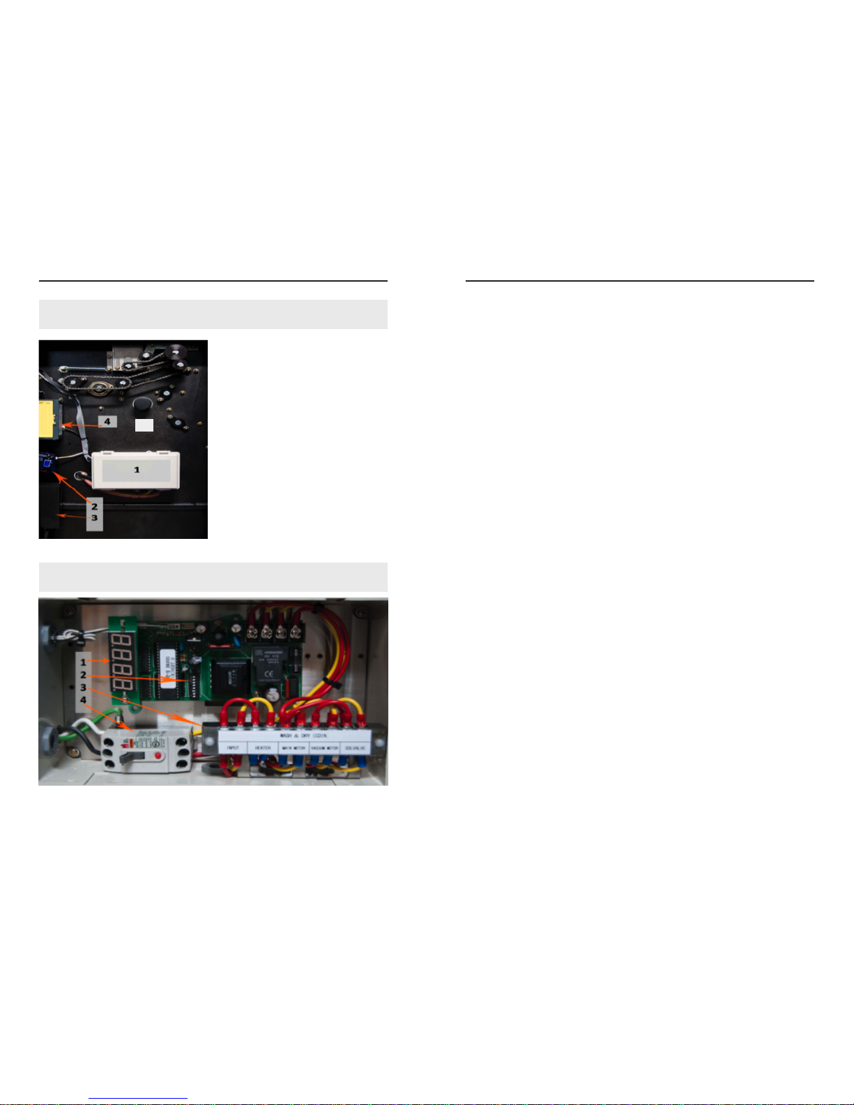
1. Control Box
2. Coin Acceptor
3. Coin Collection Bin
4. Bill Acceptor
5. Extraction Chamber
1. Digital Counter
2. Control Box Dip Switches
3. Electrical Connection Board
4. Circuit Breaker
1. If the four included castor wheels are to be utilized for easy
mobility, please ensure they are installed PRIOR to all other setup.
REMEMBER to utilize built-in brakes when the machine is stationary.
2. Position the machine on a level surface, free from obstructions and out
of the way of trafc.
3. Extend the rear mat catch rack and secure to the rst or second notch
on both arms.
4. Clamp and position exterior drainage hose pointing down at drain or
connect extended drainage line as needed at your location.
5. Connect line from water source to the water valve inside of the Left
Side Panel. REMEMBER to apply hose clamp tightly. A loose hose
clamp will result in leakage.
6. Pull power cord through the cut out hole and connect the End-Plug
(not included).
7. Plug in to a 110v, 30 amps power source to begin conguration.
CRITICAL INFORMATION: Using a power source rated for less
than 30 amps may result in irreversible damage to the machine
and property. Please exercise extreme caution when working with
electricity and electrical components.
(Apply to both Full-Serve and Self-Serve models)
NOTE: When opening doors or panels using the provided keys,
always turn the keys together at the same time.
5
10
OPERATIONS MANUAL
11
RHINO-MAT
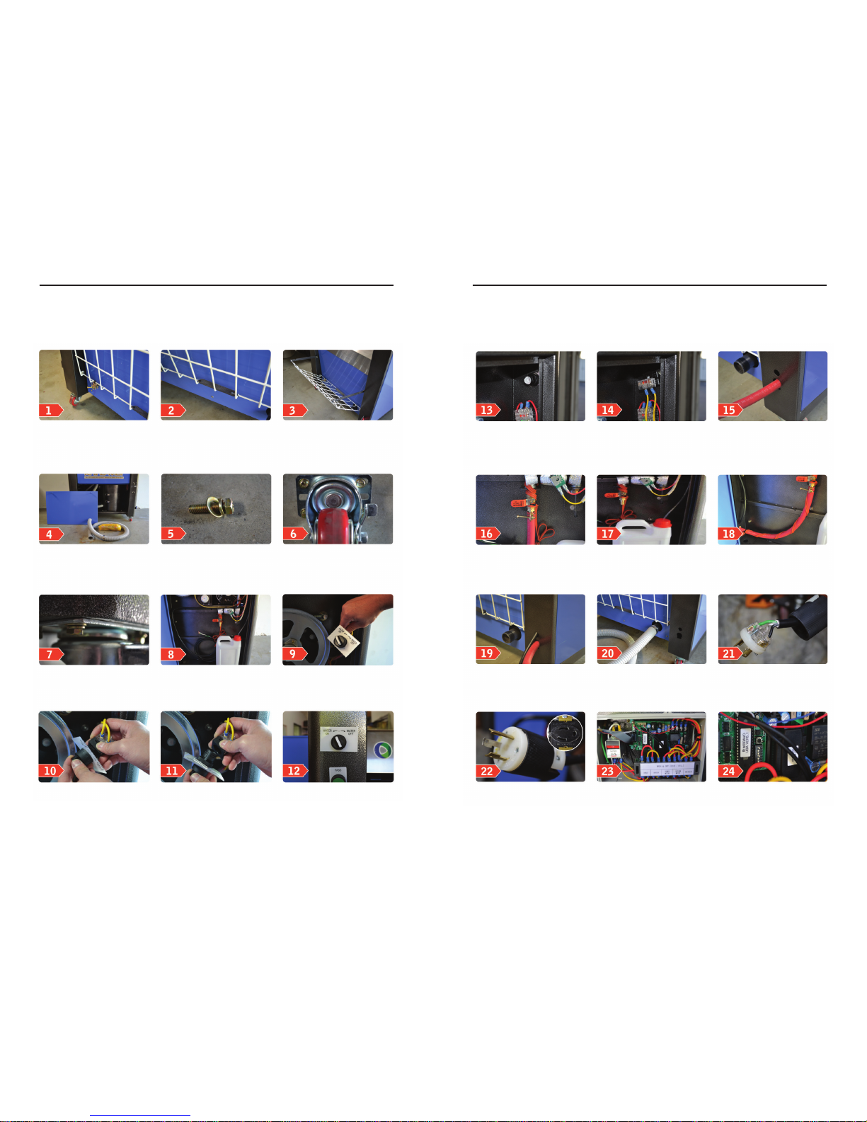
Remove the keys (6) including
(1) clamp for the water line
that are attached on the oor
mat tray
Remove the top hood stands Fully Extend the rack to
maximize the use of the tray
Remove the keys (6) including
(1) clamp for the water line
that are attached on the oor
mat tray
Remove the top hood stands 4x bolt, washer and lock
washer for each caster
Bolt down securely Open left door panel for
power and water installation
Installation for water on, water
off
Disconnect the switch from
the power connection
Push the lever on the power
connection to disconnect
the switch. Remove plastic
tightner and metal fastener
attachment
Place placard and switch on
panel wall
Apply the metal fastener rst
then the plastic tightner as
shown
Apply the power connection
circuit, you should hear a
“click” sound. Check to make
sure the connection is properly
attached
Insert a 5/8 inch standard
hose for your water
connection
Secure tightly with the
fastener provided with the
unit
Fill up the chemical soultion
in porvided 1 gallon jug
Secure the heat tape to the
water connection
Pull the electrical connection
through the electrical port as
shown
Connect the drain hose with
the provided fastner. The drain
hose should have a clear path
to the drain
Use a 3 prong connection.
Please have a qualied
electrician complete
Secure. 110V dedicated outlet
and dedicated 30Amp breaker.
Please have a qualied
electrician complete this step
R ight side door panel has
access to the control box
which houses the motherboard
and internal breaker
Dip switches control how long
the machine runs every cycle.
Black button is used when
resetting the unit

12
OPERATIONS MANUAL
13
RHINO-MAT
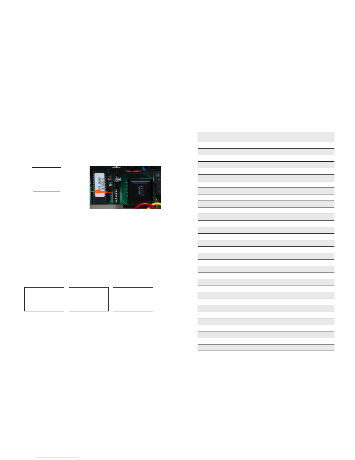
1. Congure the automatic
shutoff feature and the
delay timer using the
Dip Switches located
inside of the control box.
Manufacturer highly
recommends a delay of
5-10 seconds between 3-4
minute cycles. See Page
11 for a chart with the Dip
settings.
WARNING!: Running multiple cycles repeatedly without allowing the
machine time to drain will result in damage to vacuum motor(s) not
covered by the warranty.
2. Circuit breaker switch to
“ON”. Press the red reset
button to ensure circuit is
closed.
THE FOLLOWING PROCEDURES DO NOT APPLY TO THE SELF-
SERVE MODEL CONFIGURED FOR PAYMENT. PLEASE REFER TO THE
NEXT SECTION FOR INFORMATION ON SETTING UP THE PAYMENT
COMPONENTS.
Once the machine has been setup and placed in its nal operating location,
conguration consists of two nal steps.
Run Time
(MM:SS) SW 1 SW 2 SW 3 SW 4 SW 5 SW 6
01:00 OFF OFF OFF OFF OFF OFF
01:30 OFF OFF OFF OFF OFF
02:00 OFF OFF OFF OFF OFF
02:30 OFF OFF OFF OFF
03:00 OFF OFF OFF OFF OFF
03:30 OFF OFF OFF OFF
04:00 OFF OFF OFF OFF
04:30 OFF OFF OFF
05:00 OFF OFF OFF OFF OFF
05:30 OFF OFF OFF OFF
06:00 OFF OFF OFF OFF
06:30 OFF OFF OFF
07:00 OFF OFF OFF OFF
07:30 OFF OFF OFF
08:00 OFF OFF OFF
08:30 OFF OFF
09:00 OFF OFF OFF OFF OFF
09:30 OFF OFF OFF OFF
10:00 OFF OFF OFF OFF
12:00 OFF OFF OFF
15:00 OFF OFF OFF OFF
18:00 OFF OFF OFF
20:00 OFF OFF OFF
25:00 OFF OFF
30:00 OFF OFF OFF OFF
35:00 OFF OFF OFF
40:00 OFF OFF OFF
00:10 OFF OFF
00:20 OFF OFF OFF
00:30 OFF OFF
00:40 OFF OFF
00:50 OFF
Delay Time (MM:SS) SW 7 SW 8
00:05 OFF OFF
00:10 OFF
14
OPERATIONS MANUAL
15
RHINO-MAT
The rst step to setting up the bill and coin system is to gure out these three factors:
The Length of Time (in seconds)
you plan to give
your customers per cycle:
1 minute = 60 Seconds
The Dollar Amount (in quarters)
you plan to charge
your customers per cycle:
1 dollar = 4 quarters
Also, it is important to note that 1 quarter = 1 pulse; so 4 quarters = 4 pulses.
Locate Control Panel Dip Switches 1-8 in the Control Box located on the inside
of the Right Side Door.
The following procedures DO NOT apply to the Full-Serve, Push Button
Start models.
1. Determine the length of time per cycle in seconds
(i.e. 2 minutes=120 seconds).
2.Next, determine the dollar amount to be charged per cycle in quarters
(i.e. $2= 8 quarters [each quarter= one pulse]).
Once you have these two numbers, plug them into the following equation:
_______________ ÷ ______________ = _______________
3. Finally, once you have the “DIP Switch Settings for Time”, nd the number
under the Seconds column on the Control Box DIP SW Chart for Setting
Time (Located on Page 15). These are the settings that DIP switches 1-5
should be set to.
NOTE: You will need to round the number up or down if you end up with
a fraction (i.e. 24.5 can round up to 25 or down to 24).
Seconds DIP SW 1 DIP SW 2 DIP SW 3 DIP SW 4 DIP SW 5
1 OFF OFF OFF OFF OFF
2OFF OFF OFF OFF
3 OFF OFF OFF OFF
4 OFF OFF OFF
5 OFF OFF OFF OFF
6OFF OFF OFF
7 OFF OFF OFF
8OFF OFF
9 OFF OFF OFF OFF
10 OFF OFF OFF
11 OFF OFF OFF
12 OFF OFF
13 OFF OFF OFF
14 OFF OFF
15 OFF OFF
16 OFF
17 OFF OFF OFF OFF
18 OFF OFF OFF
19 OFF OFF OFF
20 OFF OFF
21 OFF OFF OFF
22 OFF OFF
23 OFF OFF
24 OFF
25 OFF OFF OFF
30 OFF OFF
35 OFF OFF
40 OFF
45 OFF OFF
50 OFF
55 OFF
60
LENGTH OF TIME
Per cycle
in seconds
DOLLAR AMOUNT
to be charged per
cycle in quarters
DIP SWITCH
Settings
for Time

16
OPERATIONS MANUAL
17
RHINO-MAT
Now take the ‘Dollar Amount to be charged per cycle in quarters’ and look at
the Control Box DIP SW Chart for setting price below. Find the correct value
under the Coin column and set the switches accordingly.
That completes the conguration of the Control Box Dip Switches.
Price Pulses (Dollars) DIP SW 6 DIP SW 7 DIP SW 8
1 ($0.25) OFF OFF OFF
4 ($1.00) OFF OFF
5 ($1.25) OFF OFF
8 ($2.00) OFF
12 ($3.00) OFF OFF
16 ($4.00) OFF
20 ($5.00) OFF
25 ($6.25)
Step by Step example:
The desired length of time per cycle is 3 minutes,
which equals 180 seconds.
The desired dollar amount to be charged per cycle is $2.00,
which equals 8 quarters or 8 pulses.
Now the equation:
180 seconds ÷ 8 quarters = 22.5 = 23
Seconds DIP SW 1 DIP SW 2 DIP SW 3 DIP SW 4 DIP SW 5
23 OFF OFF
DIP SW Chart for Setting Time
Coin DIP SW 6 DIP SW 7 DIP SW 8
23 OFF
DIP SW Chart for Setting Price System
Commonly Used Pricing and Time Combinations
Dollar Amount
to be charged $
Time
in Min. SW 1 SW 2 SW 3 SW 4 SW 5 SW 6 SW 7 SW 8
$1.00 1 OFF OFF OFF OFF OFF
$1.00 2 OFF OFF OFF OFF OFF OFF
$2.00 2 OFF OFF OFF
$2.00 3 OFF OFF OFF
$3.00 3 OFF OFF OFF OFF
$3.00 4 OFF OFF OFF OFF
$4.00 4 OFF OFF OFF
$4.00 5 OFF OFF OFF OFF
$5.00 4 OFF OFF OFF
$5.00 5 OFF OFF OFF
LENGTH OF TIME
Per cycle
in seconds
DOLLAR AMOUNT
to be charged per
cycle in quarters
DIP SWITCH
Settings
for Time

18
OPERATIONS MANUAL
19
RHINO-MAT
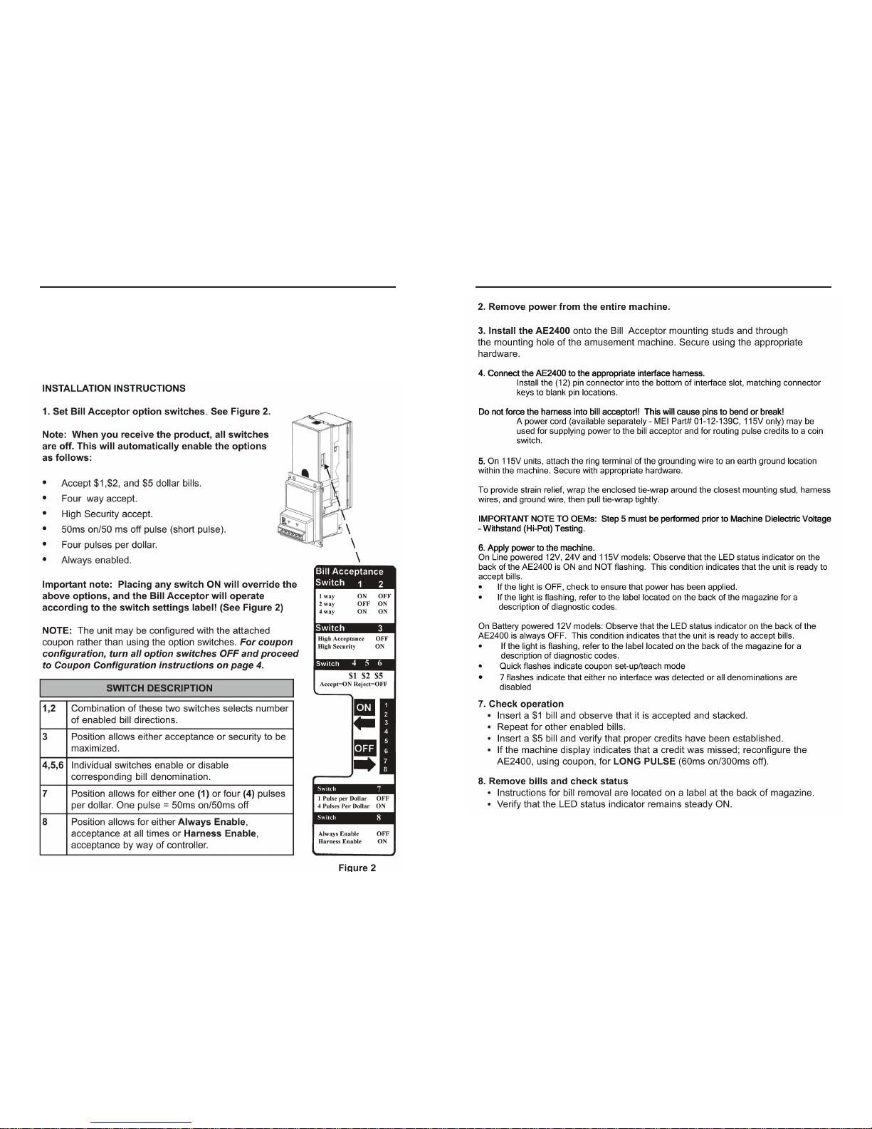
1. Slide the front cover up and identify the three controls to be used in this
procedure:
a) The “test” push button near center bottom. (used to input the number
of credit pulses)
b) 16 position rotary switch to the right of the push-button. (#0 is normal
RUN position, #1-#6 are for learning each of 6 possible coin types that
can be accepted)
c) LED indicator half way up on the right side. (Green in RUN mode, red
in LEARN mode)
2. Turn the rotary switch to one of the LEARN positions #1-#6 (for example,
pick #3 for learning the 3rd coin type) and observe the LED turns red to
indicate it is now ready to learn.
3. Push the test button once for each credit pulse you wish to have issued
for this coin. For example, a $1 coin would require 4 credit pulses if you
are also accepting $0.25 coins for one credit pulse. Note: With V3.0-t or
and V4.0 rmware, only a single credit and sense pulse will be produced
no matter how many times you push the button. Contact the factory if
you require multiple pulses for your application.
4. Slide the cover back on the unit to make sure outside light is does not
interfere with the sensors.
5. Show the unit 6 samples of the coin by depositing them into the acceptor
as usual. It is best to use 6 different coins since there are typically slight
variations from coin-to-coin.
6. After the 6th sample coin is deposited, the LED will ash red-green a
few times to indicate the LEARN procedure is complete and the coin
parameters are stored in memory.
1. Slide the front cover up and turn the rotary switch to the coin # position
you wish to UN-LEARN.
2. Push the test button once to initiate the LEARN sequence.
3. Turn the rotary switch back to position #0 without depositing any coins
to signal the unit that you wish it to erase the parameters for this coin.
The LED will ash red-green to indicate completion.
4. Slide the front cover back down.
Hawk Exeptor coin acceptor is supported directly by IDX Inc, Clean World
Distribution Inc can only provide basic support or replacement of the
component in the event of a catastrophic failure. For trouble shooting and
all other support please contact IDX Inc directly via their toll free number:
800-643-1109 or on the web at www.idxinc.com
7. Slide the front cover open again and turn the rotary switch back to
position #0 and observe the LED turning green. Check that you have
not accidentally turned it too far to position #15 which is a eld test
function position, in which it will not accept coins.
8. Slide the front cover back down and you should now be able to accept
the new coin.
20
OPERATIONS MANUAL
21
RHINO-MAT
The following instructions have been provided courtesy of MEI Group.
Clean World Distribution holds no responsibility for claims made by MEI Group.
AE2400 Bill Validator is supported directly by MEI Group, Clean World Distribution, Inc. can only provide basic
support or replacement of the component in the event of a catastrophic failure. For all other support please
contact MEI Technical directly via their toll free number: 800-345-8172 or on the web at www.meitechnical.com
22
OPERATIONS MANUAL
23
RHINO-MAT
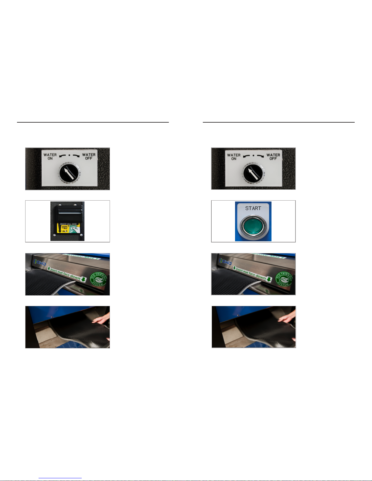
Select water switch to
“On” or “Off” position
Insert rst mat face
down
Press the green
Start Button to begin
the cycle
Collect the nished mat
from the catch rack to
the rear of the machine
Select water switch to
“On” or “Off” position
Insert rst mat face
down
Insert payment
to begin
the cycle
Collect the nished mat
from the catch rack to
the rear of the machine

24
OPERATIONS MANUAL
25
RHINO-MAT
Q: What if the mat gets stuck or jammed in the machine?
A: Open the Top Hood; Open the top hood by sliding ngers into the mat-
feeding slot with palms facing up.Curl your ngers up to hook onto the hood
release bar. Gently pull back on the bar and lift the hood open.
Simply grab and pull out stuck mat from the machine, it’ll release with ease.
Q: What if water is not being released through the Spray Bar?
A: Check to see that the water hose is tightly secured to the input valve.
Make sure that the line-in valve lever is in the open position (lever should be
pointing downward). Ensure a proper ow from the primary water source to
the machine. The “Water ON-OFF” knob on the front of the machine should
be set to “Water-On”. Check the water pipe to make sure that pipe holes are
clear and not clogged by dirt particles or build up.
Q: What do I do if water is leaking from the hose connection?
A: Ensure that the hose is tightly connected at both ends Check that the hose
connector ts properly and that the hose is clamped properly. If the hose
disconnects from the machine as water ows, it could be due to pressure built
up by the water source. Adjust water ow to less than maximum ow from the
source.
Q: Why does the mat still feel wet coming out of the machine?
A: Depending on the mat material, dryness of mats may vary from one mat
type to another. After cleaning cycle is nished, there may be slight moisture
left on the surface of the mat. The moisture still left on the surface is normal
and will dry up quickly by air. This does not mean that the machine is not
functioning properly.
Q: Why is water not owing properly from the drain hose?
A: The drain hose may be clogged due to an excess of waste. Make sure
the drain hose clamp is tightly secured. Be sure drain hose is pointing in a
downward position. Drain hose must not be bent or in an upright position.
WARNING! In select models, the Drain Hose must be completely pulled
out from inside machine to allow continuous ow of waste and liquid to
avoid over-ow.
Q: Is there any maintenance required or parts that need to be replaced?
A: It is recommended to check the machine for proper installation if the
machine does not function normally or does not start. Parts or components
that may need to be replaced due to wear and tear from normal use
or damage must be changed out immediately for normal function and
prolonged use of the system. Occasional cleaning is recommended.
Exterior should be cleaned off if there has been any contact of chemicals
or detergents onto the surface coating of the machine to prevent paint
deterioration and/or rusting.
Frequently check for excess waste left behind in drain hose and system
waste compartment, to prevent clogging and malfunction and/or damage to
system.
Q: Why do I see smoke coming out of the machine?
A: When the vacuum drum is subjected to constant use, without time to
drain, water will eventually reach the top of the vacuum drum and damage
the vacuum motor(s).
When a motor is burned out by water damage, it will create billowing smoke.
The machine will not be able to operate properly without functional vacuum
motors.
PRECAUTION: To avoid damage or malfunction of machine, please
follow all installation and safety instructions carefully and completely.
Not following these instructions may lead to injury to personnel,
damage, and malfunction to machine and its properties.

26
OPERATIONS MANUAL
27
RHINO-MAT
DISCONNECT FROM POWER SOURCES BEFORE PERFORMING
MAINTENANCE PROCEDURES.
Period Between Maintenance: Every 2 weeks or as needed
Date of last maintenance: ___________
Maintenance consists of removing tangled hair, threads and other foreign
objects from brush roller using pliers or ngers.
Access Point: Top Hood; always utilize the included hood stands any time
you are doing maintenance on interior components.
Period Between Maintenance: Every month or as needed
Date of last maintenance: ___________
Maintenance consists of opening the hatch and cleaning the extraction drum
of any built up debris and particulates over a period of time.
Access Point: Bottom front panel; turn both keys simultaneously and the
panel aside during maintenance.
Period Between Maintenance: Every month or as needed
Date of last maintenance: ___________
Maintenance consists of disconnecting drainage hoses and clearing them of
any debris and particulates that maycomponents. Build up over a period of
time. A clogged drainage hose may lead to damage to interior.
Access Point: Front access panels; turn both keys simultaneously to open
bottom panel. Utilize a Philips head screwdriver to remove two screws and
open the upper front panel.
Period Between Maintenance: Every month or as needed
Date of last maintenance: ___________
Maintenance consists of cleaning out the water drainage tray of any dirt and
debris left behind from the washing process which can eventually lead to a
clog in the interior drainage hose.
Access Point: Remove the bottom front access panel rst using the two
keys provided and the remove the top front access panel using a Philips
head screwdriver.
Period Between Maintenance: Every 12 to 18 months after purchase, or
with replacement of Sponge Roller
Date of last maintenance: ___________
Maintenance consists of clearing any clogged slits on the extraction tray.
Manufacturer highly recommends this maintenance to be performed with the
replacement of the Sponge Roller.
Access Point: Top Hood; always utilize the included hood stands any time
you are doing maintenance on interior components. Removal of Sponge
Roller may be required in order to access the full Extraction Tray.
Period Between Maintenance: Every 12 to 18 months after purchase.
Date of last maintenance: ___________
Maintenance consists of wiping away old lubricant and applying new
lubricant to all gears and chains.
Access Point: Left and Right Side Access Doors; turn both keys at the
same time when opening each door.
FLIP CIRCUIT BREAKER SWITCH TO OFF AND DISCONNECT
FROM POWER SOURCES BEFORE REPLACING ANY ELECTRICAL
COMPONENTS.
Effective life expectancy: 1 to 2 years depending on usage
Date of last replacement: ___________
Maintenance consists of an inspection to ensure the vacuum motors are still
in working condition after long periods of use. Users should not continue to
use the machine upon discovery of any damages until replacement motors
are installed.
Access Point: Back access panels; turn both keys simultaneously to open
bottom panel.
Warning: DO NOT insert ngers into any part of the vacuum motor
where moving parts are exposed!
28
OPERATIONS MANUAL
29
RHINO-MAT
Effective life expectancy: 3 to 4 years depending on usage
Date of last replacement: ___________
Maintenance consists of an inspection and thorough cleaning to ensure the
Brush Roller is free from tangled hairs and bers. Also, check to make sure
that there are no large patches of missing or broken bristles. Large patches
of missing or broken bristles indicate that the effective life expectancy has
been exceeded and the Brush Roller needs to be replaced soon.
Access Point: Top Hood; always utilize the included hood stands any time
you are doing maintenance on interior components.
Effective life expectancy: 4 to 5 years depending on usage
Date of last replacement: ___________
Maintenance consists of an inspection to ensure that the rubber brackets are
intact and not worn down too far. If the brackets are worn and look to be in
bad condition, the feeder roller will need to be replaced.
Access Point: Top Hood; always utilize the included hood stands any time
you are doing maintenance on interior components.
This maintenance and part replacement schedule is a rough
estimation. Life expectancy for replaceable parts will vary depending
on the volume of usage and operating environment.
Effective life expectancy: 1 to 2 years depending on usage
Date of last replacement: ___________
Maintenance consists of an inspection to ensure the surface of the Sponge
Roller is intact. A worn out Sponge Roller will result in mats not being
pressed down tightly enough against the extraction tray to ensure proper
drying of mats. It is highly recommended that the Sponge Roller be replaced
at the rst signs of wear and a low quality of drying.
(NOTE: Residual moisture is acceptable as it is only on the top layer and will
dry in the open air.)
Access Point: Top Hood; always utilize the included hood stands any time
you are doing maintenance on interior components.
In order to replace the Brush Roller you will need access to the left side door
panel, the top hood, and the right side door panel. Unlock the left and right
side door panels using the keys provided.
Before opening the top hood, disconnect the machine from the primary
power source.
Open the top hood by sliding ngers into the mat-feeding slot with palms
facing up. Curl your ngers up to hook them onto the hood release bar.
Gently pull back on the bar and lift the hood open.
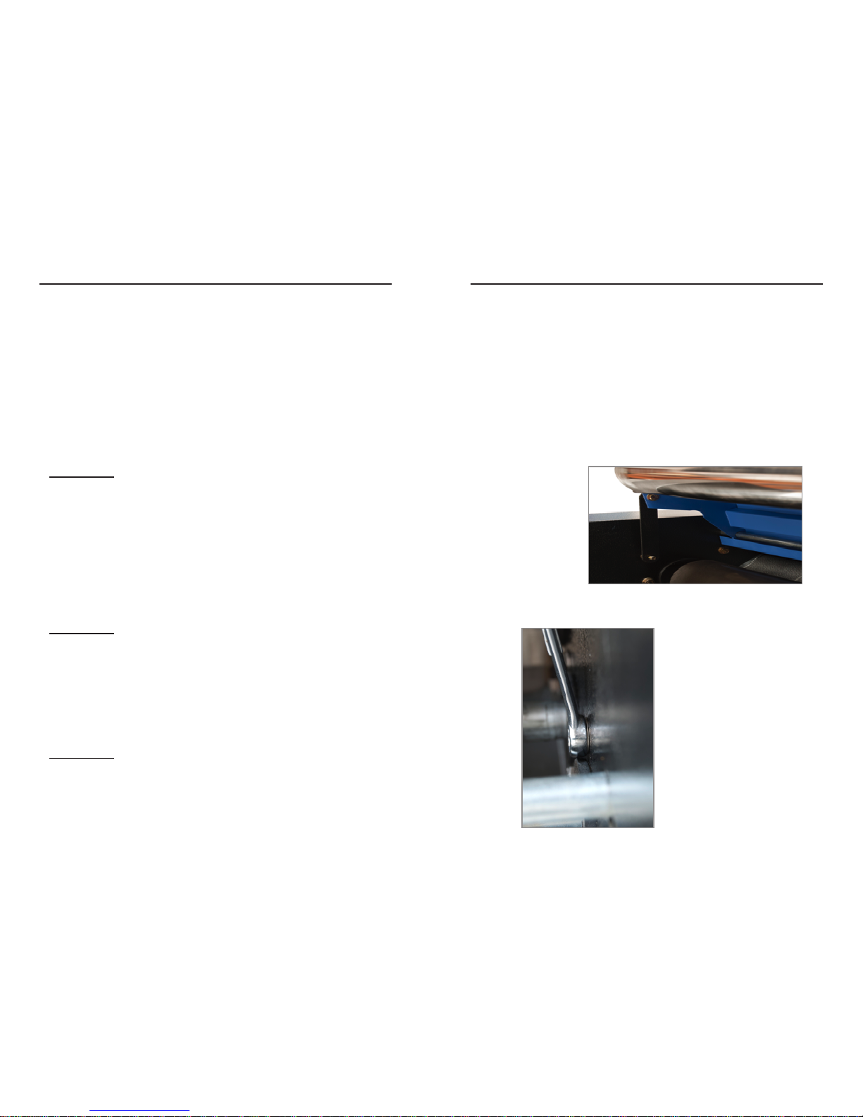
ALWAYS utilize the
hood stands to prop
the top hood open
when replacing
rollers. Remove when
work or maintenance
is complete.
When removing bolts for
bearing housings, always
hold the bolt or the nut on
the opposite side in place.
Otherwise, the bolt will
spin freely.
30
OPERATIONS MANUAL
31
RHINO-MAT
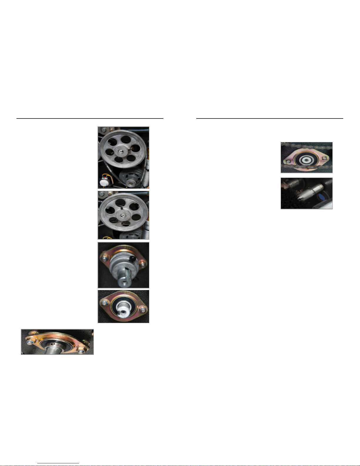
1. Remove Main Motor Belt
2. Remove Main Motor Pulley
by loosening the two black
locking bolts. A lot of force
may be needed to pull the
pulley off.
3. Remove Secondary inner
Pulley by loosening the
two black locking bolts.
4. Remove the Bearing and
lock ring.
(NOTE: The lock rings have
bolts that must be removed
with an allen wrench before
the bearing assembly can be
removed.)
5. Remove the bearing assembly
and lock ring.
6. Slowly push the Brush Roller to
the far left and lift the roller out
of the machine.
Once the old Brush Roller has been removed, installing the new one is as
simple as following the previous steps in reverse order.
1. Insert the new Brush Roller by sliding the shorter side (less rod is
exposed) into the right side hole. Push as far as needed to get the left
side into its respective hole.
2. Reattach and lock the bearing assembly and lock ring into place in the
Right Side Door panel.
3. Move over to the Left Side Door Panel, reattach the bearing assembly,
and lock ring into place.
4. Next, slide the smaller secondary pulley into place ensuring that it
lines up correctly with a corresponding pulley located to the left side.
Once it is in place, lock it down and reattach the belt between it and the
corresponding pulley.
5. Slide the Main Motor Pulley on, ensuring that it is perfectly aligned with
the pulley on the main motor. When the two pulleys are aligned, lock it
into place.
6. Finally reattach the Main Motor belt to complete the installation.
necessary in order for the pulleys to slide on smoothly.)

32
OPERATIONS MANUAL
33
RHINO-MAT
In order to replace the Sponge Roller you will need access to the top hood,
and the right side door panel. Unlock the right side door panel using the keys
provided.
Before opening the top hood, disconnect the machine from the primary
power source.
Open the top hood by sliding ngers into the mat-feeding slot with palms
facing up. Curl your ngers up to hook them onto the hood release bar.
Gently pull back on the bar and lift the hood open.
ALWAYS utilize the
hood stands to prop
the top hood open
when replacing
rollers. Remove when
work or maintenance
is complete.
When removing bolts
for bearing housings,
always hold the bolt
or the nut on the
opposite side in place.
Otherwise, the bolt will
spin freely.
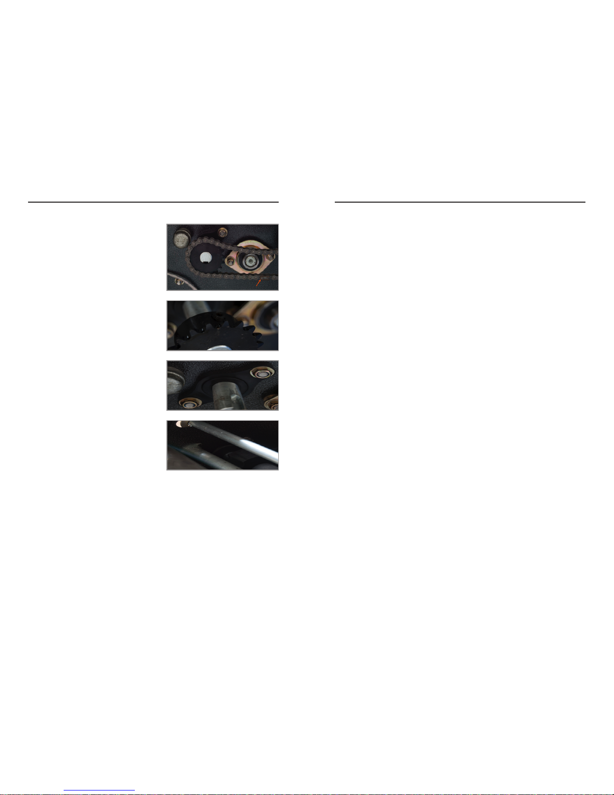
1. Unlink the chain connected
to the Sponge Roller gear by
carefully removing the chain
clip holding the removable link
in place.
2. Remove the Gear connected
to the Sponge Roller.
3. Disconnect the Top Hood
retaining bar spring by
removing the bolt.
4. Take off the outer bearing
housing by removing the four
bolts. The two bolts directly
to either side of the roller DO
NOT need to be loosened.
5. Carefully slide the bearing,
inner housing, and spring off
of the Sponge Roller rod. The
two bolts DO NOT need to be
removed as they are there to
hold the bearing to the inner
housing.
6. From the top hood pull the
Sponge Roller to the far right
and lift out of the machine.

34
OPERATIONS MANUAL
35
RHINO-MAT
1. Insert the new Sponge Roller from left to
right, ensuring that the rod end with the
notch goes through the right side hole.
Double checking this will make sure that the
gear that goes back on will have something
to bite into.
2. When re-placing the bearing, inner housing, outer housing and spring,
it will be easier to assemble the parts BEFORE trying to attach them
individually to the Sponge Roller rod. The spring has a tendency to make
things difcult as it pushes the bearing slightly off center from where the
Sponge Roller comes through.
3. Insert and tighten the four bolts for the outer bearing housing , keeping
in mind to hold the nuts and bolts from the opposite side to prevent them
from spinning freely.
4. Now hang the spring for the Top Hood
retaining bar and apply the outer washer
and nut.
5. Slide the gear back into place with one
of the locking bolts in place over the notch in the Sponge Roller rod. (Note:
It may be necessary to le down any bumps or scars on the Sponge Roller
rod in order for the gear to slide on smoothly. Any resistance felt may
indicate a spot that needs to be led down.)
6. Once the Sponge Roller gear is
aligned and in place, lock it down using
an Allen wrench.
7. When re-connecting the chain,
be sure to run the chain UNDER the
swinging arm gear, not over it before
reattaching the locking links.
In order to replace the Feeder Roller you will need access to the top hood,
and the right side door panel. Unlock the right side door panel using the keys
provided.
Before opening the top hood, disconnect the machine from the primary
power source.
Open the top hood by sliding ngers into the mat-feeding slot with palms
facing up. Curl your ngers up to hook them onto the hood release bar.
Gently pull back on the bar and lift the hood open.
ALWAYS utilize
the hood stands
to prop the top
hood open when
replacing rollers.
Remove when work
or maintenance is
complete.
When removing bolts for
bearing housings, always
hold the bolt or the nut on
the opposite side in place.
Otherwise, the bolt will
spin freely.
36
OPERATIONS MANUAL
37
RHINO-MAT
1. Unlink the chain by carefully
pulling off the locking clip.
2. Use an Allen wrench to loosen
the two locking bolts on the gear
to remove it.
3. Remove the bearing to release
the Feeder Roller.
4. Carefully pull the Feeder Roller to
the far right side and lift out.
Once the old Feeder Roller has been removed, installing the new one is as
simple as following the previous steps in reverse order.
1. Slide the new Feeder Roller into the left side rst, ensuring that the
Feeder Roller rod end with the indentation goes into the right side. This
is to make sure that the gear has a place to bite into the rod and turn the
roller.
2. Reattach the bearing and fasten the two bolts in their respective holes.
3. When attaching the gear, ensure that it is perfectly aligned so that chain
will not experience resistance when turning at high speeds.
4. Lock the chain back into place, apply lubricant as needed to complete
the installation.
To replace the vacuum motors unlock the bottom front panel using the two
keys provided. Use a Philips head screwdriver to remove two screws to open
the top front panel.
DISCONNECT THE MACHINE FROM THE PRIMARY POWER SOURCE
PRIOR TO COMPLETING ANY OF THE FOLLOWING PROCEDURES.
FAILURE TO DO SO WILL LEAD TO SEVERE INJURY.
1. Open the bottom front panel using the two keys provided.
2. Open the top front panel by removing two screws with a Philips head
screw driver.
3. Disconnect the two power cables for each motor where they are joined to
the two coming from the machine.
4. Disconnect the vacuum hoses by loosening the attached hose clamps.
5. Free the vacuum motors from the top of the extraction drum by removing
the mounting brackets.
6. Place new vacuum motors in their proper position and secure them tightly
to the extraction drum using the mounting brackets.
7. Reconnect vacuum hoses and secure with hose clamps.
8. Each motor has two cables on left and right (+ and -) sides. Twist the left
side cables (+ and +) from both motors together and do the same for the
right side cables (- and -) so that you are left with only two cables coming
from the motors.
9. Then connect the two lines from the motors to the two lines coming from
the machine to complete the process. Usually the two lines from the
machine are different colors, it does not matter which go to which as long
as they never touch.

38
OPERATIONS MANUAL
39
RHINO-MAT
The following list of tips has been created to provide operators of Rhino-Mat
effective ways to work out the older more soiled in stains. By employing the
techniques and information provided below, operators will be able to maximize
on Rhino-Mat’s full potential to provide a completed product matched by no
other machine on the market.
Due to the brush only being able to spin in one direction, mats of certain
materials or those that are stained very heavily, may not always come out
as clean as is possible on the rst run. The different grades of the bers
will sometimes lead to only one side being cleaned.
It is highly recommended that these particular mats be turned 180
degrees so that the brush is able to spin against the opposite side
of the bers thus enabling a more thorough cleaning. Even for those
mats that come out looking clean, can get cleaner by utilizing this
method.
Using the chemical injection system may not always be the most effective
choice depending on the recommended dilution of the cleaning solution
being used. Tougher stains may require a more concentrated application
of solution in order to be lifted out.
In some cases, pre-treatment may be required in order to thoroughly
remove the more stubborn stains. (Please note: it is highly
recommended that a low foam or a non-foaming upholstery cleaner
be used.)
Depending on the materials that some mats consist of, they may not
always come out as dry as is possible.
All Rhino-Mat systems come equipped with “Water On-Off” toggle
switches. In the event that mats come out feeling moist or wet to
the touch, switch the water off and run the mat through again to dry
completely.
Hot water will always help. While the effectiveness of Rhino-Mat System
lies primarily in patented technology, the application of hot water will
always boost the quality of the end product that Rhino-Mat is able to
provide. If a warm water line is available, capitalize on Rhino-Mat’s
effective technology coupled with the cleaning power of hot water.
This manual suits for next models
2
Table of contents


