Cleanco TM FLOODMASTER Operation manual

1
TM FLOODMASTER
Operations and Service Manual
VERSION Sept. 2023
Printed in Canada

2
Table of Contents……………………………………………………………………………2-3
Machine Data Log……………………………………………………………………………....4
Safety Instructions……………………………………………………………………………5-9
Technical Specifications………………………………………………………………………10
Receiving Your Truckmount…………………………………………………………………. 11
Installation Requirements……………………………………………………………………..12-13
Battery Connection…………………………………………………………………………… 13
Fuel Requirements…………………………………………………………………………….14
Engine Requirements………………………………………………………………………….14
General information………………………………………………………………………….15-16
- Waste Water Disposal
- Operating in Hot Weather
Operating Instructions……………………………………………………………………….17-18
- Start Up
- Shut Down
Vacuum System…………………………………………………………………………………18
Electrical System………………………………………………………………………………..19
Hays Rear Bearing Support……………………………………………………………………19
Upper Front Panel………………………………………………………………………………20

3
Recovery Tank…………………………………………………………………………………21
Maintenance……………………………………………………………………………………22
- Daily
- Weekly
- Monthly
- Quarterly
Service Interval Chart…………………………………………………………………………23
Trouble Shooting…………………………………………………………………………..24-25
Helpful Tips…………………………………………………………………………………26-29
Fuse Panel……………………………………………………………………………………29
Wiring Daigram……………………………………………………………………………… 30
Schematics …………………………………………………………………………………31-43
Recmmended Fluids for Maintenance……………………………………………………..44

4
MACHINE DATA LOG / OVERVIEW
Welcome…and congratulations on the purchase of your Cleanco TM Floodmaster. This instruction
manual is a guide for operating and servicing your unit. Read this manual completely before
installing or operating this unit. This unit offers you personal convenience. All of your
instrumentation and controls have been positioned to give you easy access for operation and daily
maintenance.
Proper operation and service are essential to the efficient functioning of this unit. When maintained
correctly, this unit will have a long, trouble-free life.
The service methods described in this manual are explained in such a manner that serving may be
performed accurately and safely. Proper service varies with the choice of procedure, the skill of the
mechanic, and the tools or parts available. Before attempting any repair, make certain that you are
thoroughly familiar with this equipment and are equipped with the proper tools. Any questions
pertaining to operation or servicing this unit should be directed to your nearest dealer.
THIS UNIT MUST BE INSTALLED BY THE DEALER FROM WHOM YOU PURCHASED IT IN ACCORDANCE
WITH THE PRESCRIBED INSTALLATION PROCEDURES.
MAKE CERTAIN THAT THE WARRANTY FORM IS FILLED OUT AT THE TIME OF INSTALLATION AND
RETURNED TO: ESTEAM MANUFACUTRING OR;
BY REGISTERING YOUR WARRANTY ONLINE AT: https://esteam.com/warranty-enrollment/
MODEL________________________________________________
DATE OF PURCHASE_____________________________________
SERIAL NUMBER________________________________________
COMPANY NAME_______________________________________
YOUR DEALER
NAME:_________________________________________________________
ADDRESS:_______________________________________________________
PHONE NUMBER:________________________________________________

5
IMPORTANT SAFETY INSTRUCTIONS
When using this machine, basic precautions must always be followed, including the following:
READ ALL INSTRUCTIONS BEFORE USING THIS MACHINE
These symbols mean WARNING or CAUTION. Failure to follow warnings and cautions
could result in fatality, personal injury to yourself and/or others, or property damage.
Follow these instructions carefully.
Read the operator’s manual before installing or starting this unit. Failure to adhere to instructions could
result in severe personal injury or could be fatal.
Operate this unit and equipment only in a well-ventilated area. Exhaust fumes contain carbon monoxide,
which is an odorless and deadly poison that can cause severe injury or fatality. DO NOT run this unit in an
enclosed area. DO NOT operates this unit where the exhaust may enter any building doorway, window, vent, or
opening of any type.
This unit must be operated with the vehicle doors open in order to ensure adequate ventilation to the engine.
In hot climates roof vents are recommended for added ventilation and cooling.
Never operate the TM Floodmaster with a portable gas container inside the vehicle. Doing so will increase the
risk of fire and explosion. Serious injury or death may result.
DO NOT place hands, feet, hair, or clothing near rotating or moving parts. Avoid any contact with moving
parts! Rotating machinery can cause injury or fatality.

6
Never operate this unit without belt guards or hoods. The high-speed moving parts, such as belts and
pulleys, should be avoided while this unit is running. Severe injury, damage or fatality may result.
DO NOT service this unit while it is running. The high-speed mechanical parts as well as high temperature
components may result in severe injury or severed limbs.
Never touch electrical wires or components while the engine is running. They can be sources of electrical
shock.
Before servicing this unit, allow it to “cool down.” This will prevent burns from occurring.
NEVER leave the vehicle engine running while the unit is in operation.
Always wear hearing protection when unit is running. Always comply with local noise ordinance when
operating units.

7
Dangerous Acid, Explosive Gases! Batteries contain sulfuric acid. To prevent acid burns, avoid contact with
skin, eyes and clothing. Batteries produce explosive hydrogen gas while being charged. To prevent a fire or
explosion, charge batteries only in well-ventilated areas. Keep sparks, open flames, and other sources of
ignition away from the battery at all times. Keep batteries out of the reach of children. Remove all jewelry when
servicing batteries.
Before disconnecting the negative (-) ground cable, make sure all switches are OFF. If ON, a spark will occur at
the ground cable terminal which could cause an explosion if hydrogen gas or gasoline vapors are present.
When disconnecting the battery, ALWAYS disconnect the negative (-) terminal FIRST.
DO NOT smoke around the unit. Gas fumes may accumulate and be ignited. The battery is also extremely
flammable. This will prevent possible explosions.
DO NOT damage the vehicle in any manner during installation. When routing fuel lines DO NOT place the
hose in any location where damage may occur to the hose or vehicle. Avoid any contact with moving parts,
areas of high temperature, brake lines, fuel lines, muffler, catalytic converter, or sharp objects.
DO NOT exceed your vehicle’s payload capacity. Check with the vehicle manufacturer for the gross Vehicle
weight Rating (GVWR) GVWR is the maximum allowable combined weight of the vehicle, including all
passengers, fuels, tools, and cargo.
DO NOT operate this unit without the filters installed in the waste tank.

8
Never operate the TM Floodmaster when the vehicle is tilted more than 10 degrees in any direction. Doing so
will result in improper lubrication of the internal components and will increase the risk of serious component or
engine damage.
Never operate the TM Floodmaster with vehicle doors closed. Doing so results in extremely high temperatures
inside the vehicle and will lead to serious component or engine damage.
Failure to apply preventive measures towards freezing can result in system failure and loss of warranty on
affected parts. Water freezes at 32⁰F or 0⁰C.
Do not modify this unit in any manner. Use only replacement parts authorized by Cleanco. Modifications
or use of unapproved parts could create a hazard can cause severe personal injury or fatality and will void your
warranty.

9
This unit creates high temperature on some components, improper or irresponsible use may result in
serious injury.
Make certain that you receive complete training by the distributor from whom you purchased this unit.
Any modification of the TM Floodmaster may void the warranty.
10
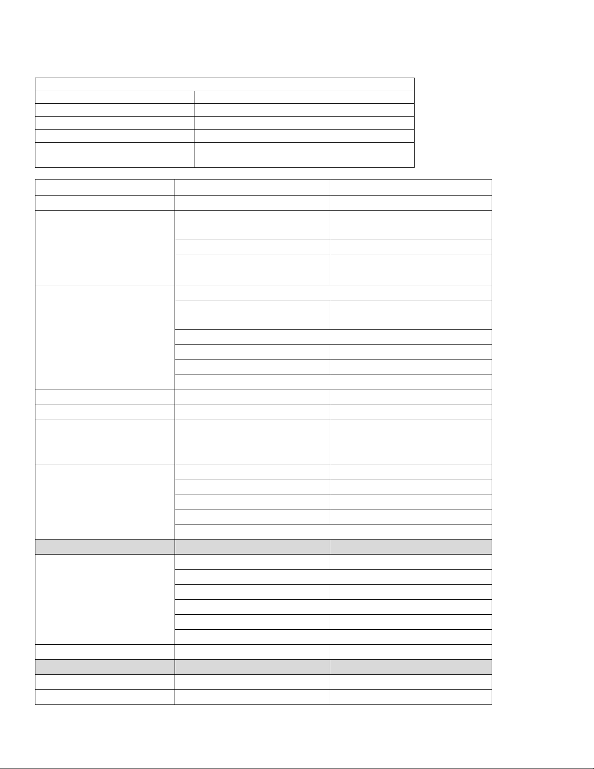
TECHNICAL SPECIFICATIONS
ITEM
DIMENSION/CAPACITY
Engine speed
2850 rpm (high speed)
Vacuum pump rpm
2850 rpm
Vacuum relief valve
13” Hg
Waste tank capacity
90 gallons (340.69 lt)
Console weight
700 lbs.
Blower Belt size
BX41
Frame Dimensions
D=38" x W=22.5" x H=46.25"
Weight Console only
700 lbs
Engine - Kubota
Oil Type
SAE viscosity and SH class
grades (API classifications)
Above 25C (77F)
SAE30 or SAE10W-30
0C to 25C (32F to 77F)
SAE20 or SAE10W-30
0C to -20C (32F to -4F)
SAE10W or SAE10W-30
Oil Capacity
3.4 L (0.90 U.S. gals) when
changing oil and filter
Engine rpm
High - 2850
Idle - 1850-1900
Ignition
Key ignition
Vacuum Blower - Tuthill
Trilobe 4007 (Dual
Splash Lubrication)
Oil Type
MD-ONE Blower Oil
Gear End Capacity
Approx. 5.8 oz (171.5 ml)
Drive End Capacity
Approx. 4.7 oz (139 ml)
Blower rpm
Standard Equipment
Vacuum Hose
2" Vacuum Hose - 100 ft
Lead Vacuum Hose
10 ft x 1.5”
Recovery Tank
90 gallon (340.69 litres)
Battery Box
Optional
External Pump Out (APO)
237-040
Optional
Exhaust Kit
600-235

11
RECEIVING YOUR TRUCKMOUNTED UNIT
DEALER RESPONSIBILITIES
The Esteam / Cleanco authorized dealer that you purchased this unit from is
responsible for:
1. Correctly installing and properly securing equipment with proper hardware and underside mounting plates.
2. Checking the components and oil levels prior to starting the unit.
3. Check that all components are operating at the factory specifications.
4. Checking all hoses and accessories for correct operation.
5. Checking all tools / wands for correct operation.
6. Training you in the operation, maintenance, and safety precautions of your unit.
It is the purchaser’s responsibility to become familiar with the entire Owner’s Manual, most of all Warnings, Cautions, and
Notices.
ACCEPTANCE OF SHIPMENT
Your TM Floodmaster truckmount was thoroughly tested, checked and inspected in its entirety prior to leaving our
manufacturing facility. When receiving your unit, please make the following acceptance check:
1. The unit should not show any signs of damage. If there is damage, notify the deliverer immediately.
2. Carefully check your equipment. The TM Floodmaster should arrive with the following items as well as any
optional accessories you may have ordered:
EQUIPMENT LIST
•Cleanco TM Floodmaster Console
•Recovery tank with auto shut-off
•Recovery tank vacuum hoses
•Installation mounting plates and hardware
•Hose clamps for vacuum, and fuel hoses
•100 ft of 2” vacuum hoses
•10ft x 1.5” Lead vacuum hose
•Battery Box

12
FUEL HOOK-UP KITS BY VEHICLE (If ordered)
•Dodge Promaster 2015 + 604-86392100
•Ford transit 2015 + 604-86400740
•Chevy (GM) 2003 + 604-790537
INSTALLATION REQUIRMENTS
Prior to starting installation, read the ENTIRE Installation section of this manual. Since the TM Floodmaster truckmount
weighs over 700 lbs., adhere to the following recommendations prior to installing the unit.
The unit should not be installed in any vehicle rated less than ¾-ton capacity.
DO NOT exceed the vehicles payload capacity, check with vehicle manufacturer for Gross Vehicle Weight Rating
(GVWR).
If mounting the unit in a trailer, ensure that the trailer is rated for the total weight of the unit and trailer. Electric or hydraulic
brakes must be provided, and strict compliance with all State/ Provincial and Federal laws must be maintained.
If mounting in a trailer, the TM Floodmaster console must be positioned so that it balances properly with respect to the
trailer axle. Ten percent (10%) of the unit’s overall weight (w/o accessories or water) should be on the tongue. This unit
has an liquid-cooled engine, and adequate ventilation must be provided to prevent overheating. Roof vents are
recommended for additional ventilation.
Cleanco does not recommend using any type of flooring materials that absorb water. This will result in rust and corrosion
of the vehicle floor. Rubber mats should be removed prior to installation of the unit.
Check vacuum blower and engine oil levels prior to starting the TM Floodmaster.
Start and run the TM Floodmaster and check that all systems function properly.
This unit must be bolted to the floor of the vehicle by an authorized CLEANCO DISTRIBUTOR
LIFTING THE UNIT INTO THE VEHICLE
Because the TM Floodmaster console weighs over 700 lbs., a forklift is necessary to place the unit into the vehicle. Place
the forks under the unit, using two “C” clamps; secure the console to the forks.
13
POSITIONING THE UNIT INTO THE VEHICLE
Vehicle vary in size and openings. All owners have different preferences on where in the vehicle they want their units
positioned. Cleanco highly recommends a side door installation for the TM Floodmaster. We do not recommend a rear
door installation.
FASTENING DOWN THE UNIT AND WASTE TANK
Prior to drilling any holes in the vehicle floor, check underneath the vehicle to ensure that while drilling you will not
damage the fuel tank, fuel lines, or any other vital components which could affect the vehicle safety and operation.
The console and waste tank have pre-drilled mounting holes. Drill 10 holes for mounting of console and 4 holes for
mounting waste tank. The console and waste tank can be used as a template for drilling holes.
Using the provided mounting hardware kit:
Insert the 3/8” x 3” GR2 hex head bolts with flat washers through the console and waste tank mounting holes. Place the
mounting plates onto the bolts and secure with the 3/8” flanged nut. Tighten until the console and waste tank are firmly
attached to the vehicle floor.
BATTERY CONNECTION
Battery Requirement for TM Floodmaster: 650 cranking amps
Batteries contain sulfuric acid; avoid contact with skin, eyes, and clothing. Batteries also produce explosive hydrogen
gases while charging. To prevent explosion or fire, charge batteries in a well-ventilated area only. Keep sparks, open
flames, and any other sources of ignition away from batteries at all times. Remove all jewelry prior to servicing batteries.
Keep out of reach of children.
Attach the red positive (+) battery cable from the starter solenoid on the console to the positive (+) terminal on the battery
and tighten down the nut.
Attach the black negative (-) battery cable from the ground on the console to the negative (-) terminal on the battery and
tighten down the nut.
Before disconnecting the negative (-) ground cable, ensure that all switches are in the OFF position. If ON a spark could
occur at the ground connection terminal, which could cause an explosion if hydrogen gas or gasoline vapors are present.
ALWAYS disconnect the negative (-) terminal first.

14
FUEL REQUIREMENTS
Use unleaded fuel ONLY. Use only fresh, clean unleaded gasoline with a minimum octane rating of 87. Do Not use high-
octane gasoline. Gasoline with up to, not exceeding 10% ethanol is acceptable.
NOTE: using other gasoline / alcohol blends including E20 and E85 will cause damage to engine components and will
void warranty.
NEVER cut or slice any of the vehicle fuel lines during fuel line installation. This will result in fuel leaks and potentially
dangerous conditions. Use only approved fuel hose for fuel lines. When going through the vehicle floor with fuel lines,
always utilize bulkhead adaptors. This will prevent fuel leaks and ensure that hoses are not punctured by vehicle vibration
abrasion.
ENGINE REQUIREMENTS
Use high quality oil of at least API (American Petroleum Institute) service class SG or higher. Do not use additives. High
quality 30W oil is recommended. It is never recommended to extend oil change intervals past 200 hours.
TRAINING
The distributor should provide a thorough review of the operation manual with the purchaser along with
complete instruction and operation of the truckmount in:
1. How the TM Floodmaster systems function.
2. All safety precautions and their importance.
3. How to correctly start and shut down the TM Floodmaster.
4. How to correctly operate the TM Floodmaster
5. Where and how often to check and change component oil levels.
6. How to do basic troubleshooting.
7. Complete review of the warranty and warranty procedures.
Engine Oil Capacity 3.4 L
3.59 US qts

15
GENERAL INFORMATION
The Cleanco TM Floodmaster Truckmount has been designed for the professional restorer who demands a high
performance-extraction unit. Dependable performance is the guiding principle in the design and construction of the
Cleanco TM Floodmaster. Although the Cleanco TM Floodmaster is designed with simplicity in mind, this truckmounted
extraction plant has many functions that perform simultaneously.
•Engine has to run at a continuous RPM.
•Vacuum Blower has to pull air and soiled water back from the site.
•The vacuum recovery tank stores soiled water for proper disposal.
TM FLOODMASTER SPEED SETTINGS:
•Extraction Mode 2850 engine rpm
•Idle Mode 1850 - 1900 rpm

16
WASTE WATER DISPOSAL
There are laws throughout North America that prohibit the dumping of soiled water from extraction equipment in any place
but a sanitary treatment system.
The water recovered into your unit’s recovery tank contains materials such as detergent residue and many different soil
contaminants removed from flood extraction. These materials must be processed before they are safe to re-enter our
streams, rivers and reservoirs.
In most cases, an acceptable method of waste water disposal is to discharge into a municipal sewage treatment system
after filtering out solid material such as carpet fibers. Access to the sanitary system can be obtained through a toilet, RV
dump site,etc. Always obtain permission to use these locations prior to dumping the waste tank.
Another solution to the disposal of the waste water is to equip your TM Floodmaster with the Optional TM External Pump-
out (APO). The pump-out is designed to remove waste water from the TM Floodmaster’s recovery tank system and
actively pump the water through hoses to a suitable disposal drain.
AS PER FEDERAL, STATE AND LOCAL LAWS, DO NOT DISPOSE OF WASTE WATER INTO STORM DRAINS,
GUTTERS, STREAMS, RESERVOIRS, ETC.
OPERATING THE TM FLOODMASTER IN HOT WEATHER
Cleanco recommends the following when operating the TM Floodmaster during periods of hot weather (95 ⁰or higher).
This will ensure your TM Floodmaster continues to run at 100% capacity.
1. A minimum of 9” of clearance is required on both sides of the TM Floodmaster, when installed. Ensure no other
materials are stored at the sides or on top of the TM Floodmaster. Airflow around the TM Floodmaster unit is
critical for cooling the engine and other components.
2. For vans with side barn doors open the doors as wide as possible
3. When possible keep the rear doors open while the TM Floodmaster is running, this provides cross ventilation and
will substantially reduce the temperature inside the van. Roof vents are recommended for additional ventilation.

17
OPERATING INSTRUCTIONS
NOTE: Before operating the unit, make sure you are in a well-ventilated area. Exhaust fumes from the vehicle contain
carbon monoxide and are hazardous to your health and your client’s health. Do not operate the unit or the vehicle near
any building doorways, windows, or openings of any kind.
1. Check your fuel gauge to ensure you have enough fuel for the job.
2. Lay out all hoses required. When connecting hoses start from the furthest point to be extracted and work back
towards the unit. This will ensure that you have the proper length required.
3. Do not connect the vacuum hose to vacuum port at this point; this will occur after unit is started.
START UP PROCEDURE
The TM Floodmaster cannot be run in the “IDLE” position for water extraction. This will void the warranty.
1. Make sure the van is parked on level ground, placed in the park position and the emergency brake is set and turn off
vehicle engine.
2. Turn the throttle cable to the IDLE position.
3. Pull the engine choke out if engine is cold, turn the key switch to the start position and hold for 3 seconds or until the
engine starts. Immediately push the choke cable in and let the engine idle for 2-3 minutes to warm up (do not start the
unit with the throttle out at full speed, always start the unit and let it warm up at idle speed). Once warmed up throttle
the engine up to the desired speed.
4. Connect the vacuum hose to the unit, and wand or extraction tool.
5. If the Automatic Pump -Out option is included in your unit, turn the APO switch to the on position.
6. You are now ready to start extracting water.

18
SHUT DOWN
1. Remove vacuum hoses from unit.
2. Throttle engine up to 2850
3. Allow the unit to run at high speed for 2 to 3 minutes in order to remove moisture from the vacuum blower.
4. Cap off the vacuum inlet ports on the recovery tank.
5. Spray LPS-TKX lubricant into blower lube port for 5 to 10 seconds.
6. Allow the machine to run for an additional 2 to 5 minutes under load to flush lubricant.
7. Uncap the vacuum inlet ports and run the unit at idle speed for another minute to allow vacuum blower to cool down.
8. Turn the ignition switch to the off position. (If equipped with the Optional APO turn off APO switch).
9. Remove the lift out lint basket located in the recovery tank, clean, and replace the lint basket back into the recovery
tank.
10. Always drain the recovery tank at an approved disposal site.
VACUUM SYSTEM
The vacuum system is a Tuthill Trilobe 4007 positive displacement rotary lobe blower. This high performance blower
provides incredible airflow and water lift producing maximum extraction. The blower is factory set for maximum efficiency
and longevity. The performance and life of the blower greatly depends on the care and proper maintenance it receives.
Due to the close tolerances of the internal lobes and the housing of the blower, solid objects entering the inlet of the
blower can damage the interior.
To prevent this, Cleanco installs stainless steel filter screens on the vacuum inlet inside the vacuum recovery tank. The
stainless steel filters should be removed daily or after every job and cleaned. When reinstalling the filter only thread filter
on until finger tight. The lint basket should be removed and cleaned after every job. If lint basket is not clean, it will affect
the performance of your machine. The vacuum relief valve needs to be checked bi-weekly to ensure proper functionality.
The blower is factory set for maximum efficiency and longevity at 13”Hg. Never exceed 14”Hg on the gauge. Damage may
occur to the system if 14”Hg is exceeded. For further information on the Tuthill Trilobe blower, refer to the enclosed Tuthill
Blower Manual. Foam passing through the vacuum blower can lead to serious problems with the TM Floodmaster. Keep
the waste tank free of foam, this may require the use of a defoamer. The waste tank contains a high level shut-off switch;
however the switch will not be activated by foam.

19
ELECTRICAL SYSTEM
The Cleanco Compact electrical system has been specifically designed with simplicity in mind. There are multiple wiring
harness that connect all operations of the unit. This harness is complete with specially designed plug ends, which enable
service centers easy fuse panel access and service if necessary. All wiring is coated to protect against corrosion from
moisture or water spillage.
NOTE: Whenever working on wiring system power side of units battery should be disconnected for safety.
TM FLOODMASTER REAR BEARING SUPPORT
The Hayes style engine rear bearing support is a precision engineered and balanced system that transfers power from the
unit’s engine to the vacuum system, which drives the vacuum blower. This unique system eliminates any side torque
generated from the vacuum blower. An outer casing with a large bearing protects the engine shaft and engine bearing.
The Hayes system is designed to withstand extremes of heat and friction without breaking down. The Hayes system has
two grease zerk fittings one at the front of the shaft and one at the top of the bearing. These two bearings require
greasing every 250 hours of operation. The recommended grease to be used to grease the bearings is SKF LGMT
3/0.4 bearing grease.

20
TM FLOODMASTER UPPER FRONT PANEL
HOUR / TACHOMETER METER: Reads the operating time of the unit when the unit is turned off and the engine speed
when the engine is running.
IGNITION SWITCH: The engine ignition switch provides ignition to start the engine when the key is inserted and turned.
CHOKE CONTROL: The engine choke control knob pull to open the choke for engine ignition.
THROTLE CONTROL: The engine throttle control knob. Turn counter-clockwise to open the throttle (faster speed),
clockwise to close the throttle (slower speed). For emergency slow-down, depress the center button and push the throttle
control in.
APO SWITCH: Is a pre-wired switch for the optional Cleanco TM External Pump Out. Part number 237-040.
AUXILIARY SWITCH: Is a pre-wired switch used to turn an auxiliary item on or off, if an optional item, such as a lighting
kit has been installed.
EXHAUST OUTLET: This is where the engine and blower exhaust from the unit. Exhaust fumes contain carbon
monoxide, which is an odorless deadly poison that can cause serve injury or fatality. DO NOT run this unit in an enclosed
area or with vehicle doors closed. DO NOT operate this unit where the exhaust may enter any building doorway, window,
vent, or opening of any type. (OPTIONAL: Thru Floor Exhaust Kit P/N 600-235)
Table of contents
Other Cleanco Cleaning Equipment manuals


