CleanCraft AUKM 600 User manual

AUKM 600
Sweeping Machine
AUKM 600
Operating Instruction
AUKM 600

Imprint
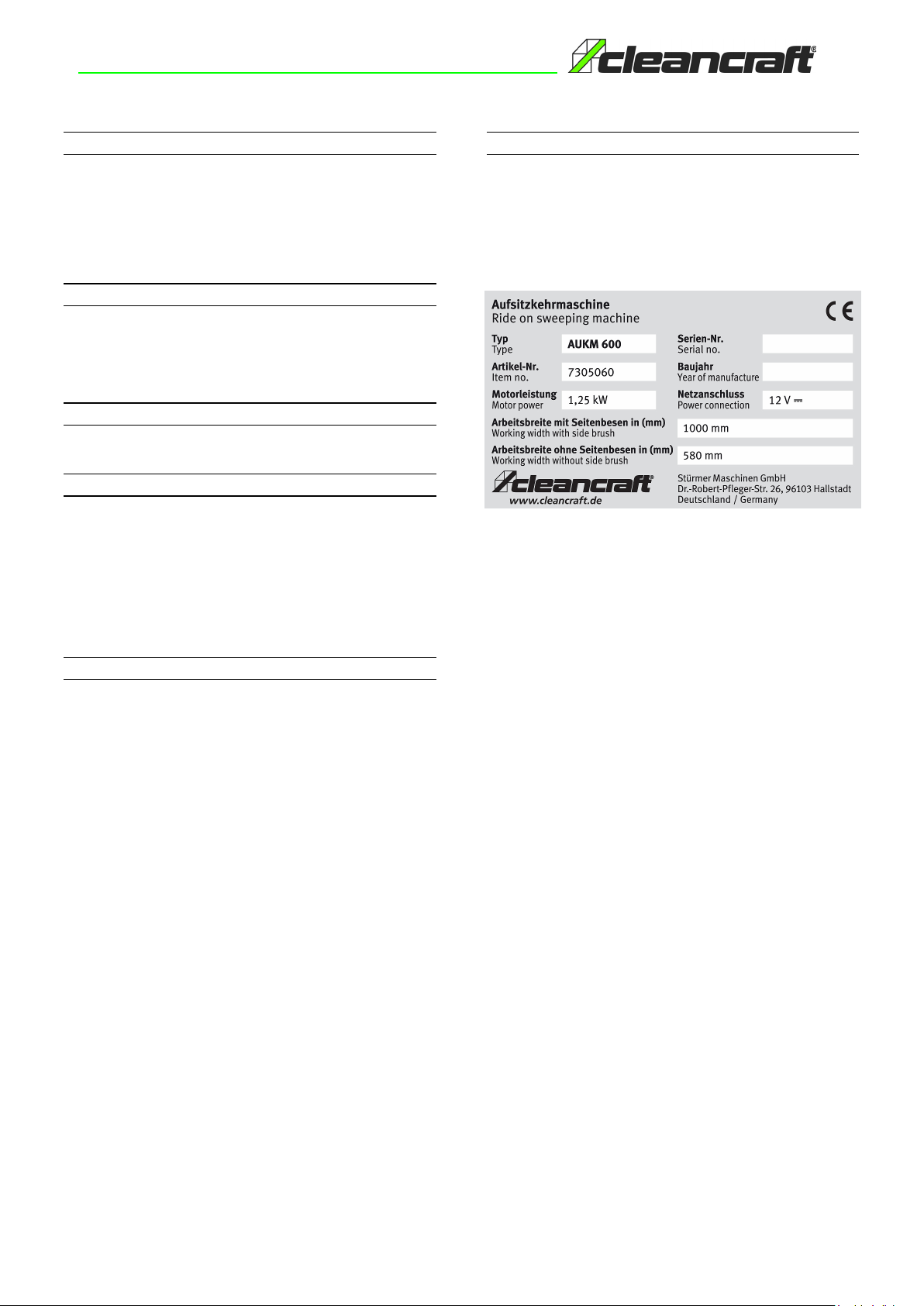
Product identification
Manufacturer
CLEANCRAFT
Sweeping Machine
AUKM 600
Stürmer MaschinenGmbH
Dr.-Robert-Pfleger-Str. 26
D-96103Hallstadt
Artikelnummer:7305060
Fax: 0049 (0) 951 96555 -55
E-Mail:
Internet: info@cleancraft.de
www.cleancraft.de
Indications regarding the operating instructions
Copyright information
Original Instructions
Edition:17.08.2017
Version: 1.01
Language:English
Author: FL
Copyright © 2017 Stuermer Maschinen GmbH, Hallstadt, Germany.
The contents of these operating instructions are the sole property of the
company Stürmer Maschinen GmbH.
Passing on as well as copying of this document, the use and distribution of
its content are prohibited if not explicitly permitted. Contraventions are
liable to compensation.
Subject to technical modifications and error.
2

The descriptions contained in this document are not binding.
The company therefore reserves the right to make any modifications at any time to
elements, details, or accessory supply, as considered necessary for reasons of
improvement or manufacturing/commercial requirements.
The reproduction, even partial, of the text and drawings contained in this document is
prohibited by law.
The company reserves the right to make any technical and/or supply modifications.
The images are for reference purposes only, and are not binding in terms of design
and supply.
SYMBOLS USED IN THEMANUAL
Open book symbol with an"i"
Indicates the need to consult the instruction manual
Open book symbol
Used to tell the operator to read the manual before using the
machine
Warning symbol
Carefully readthe sections marked with this symbol and observe
the indications, for the safety of the operator and the machine
Warning symbol
Indicates danger of gas exhalation and leakage of corrosive
liquids
Warning symbol
Indicates the danger of fire.
Do not go nearwithfree flames
Warning symbol
Indicates that the packed product should be handled with
suitable lifting means that comply with the legal requirements
Disposal symbol
Carefully read the sections marked with this symbol for machine
disposal
3

CONTENTS
ON CONSIGNMENT OF THEMACHINE....................................................................................................................................................6
INTRODUCTORY COMMENT....................................................................................................................................................................6
IDENTIFICATION DATA............................................................................................................................................................................6
TECHNICAL DESCRIPTION......................................................................................................................................................................6
INTENDED USE........................................................................................................................................................................................6
SERIAL NUMBER PLATE.........................................................................................................................................................................6
TECHNICAL DESCRIPTION......................................................................................................................................................................7
SYMBOLS USED ON THE MACHINE........................................................................................................................................................8
GENERAL SAFETY REGULATIONS.......................................................................................................................................................10
MACHINE PREPARATION......................................................................................................................................................................11
1. HANDLING OF THE PACKEDMACHINE.................................................................................................................................................................11
2. HOW TOUNPACK THE MACHINE..........................................................................................................................................................................11
3. HOW TOMOVE THE MACHINE...............................................................................................................................................................................11
4.HANDLEBAR CONTROL COMPONENTS.................................................................................................................................................................12
5. STEERING COLUMN COMPONENTS .......................................................................................................................................................................12
6.
7.
FOOTBOARDCOMPONENTS..................................................................................................................................................................................12
8. FRONT COMPONENTS..........................................................................................................................................................................................13
9. SIDE COMPONENTS..............................................................................................................................................................................................13
10.
REAR COMPONENTS OFTHE MACHINE...............................................................................................................................................................13
11. BATTERYTYPE ...................................................................................................................................................................................................13
12.
13.
BATTERYMAINTENANCE AND DISPOSAL..........................................................................................................................................................14
14.
FITTINGTHEBATTERIES INTO THEMACHINE....................................................................................................................................................14
15.
16.
CONNECTING THE BATTERIES AND BATTERY CONNECTOR ..............................................................................................................................16
17.
18.
BATTERY CHARGER CONNECTION (WITHOUT BC).............................................................................................................................................17
19.
BATTERY CHARGER CONNECTION (WITH BC)....................................................................................................................................................19
20.
BATTERY CHARGE LEVELINDICATOR ..............................................................................................................................................................19
HOUR METER.........................................................................................................................................................................................................19
WORKING FORWARD SPEED................................................................................................................................................................................19
BLINKING LIGHT (OPTIONAL)................................................................................................................................................................................19
HEADLIGHTS..........................................................................................................................................................................................................19
PREPARING TOWORK..........................................................................................................................................................................20
21.PREPARING TOWORK.......................................................................................................................................................................................20
WORK......................................................................................................................................................................................................21
22.STARTINGWORK .................................................................................................................................................................................................21
23.EMERGENCYBUTTON..........................................................................................................................................................................................23
24.EMPTYINGTHE DEBRISHOPPER.......................................................................................................................................................................23
AT THE END OFWORK..........................................................................................................................................................................25
DAILY MAINTENANCE...........................................................................................................................................................................27
25.CLEANING THE CENTRAL BRUSH.......................................................................................................................................................................27
26.CLEANING THE SIDE BRUSH................................................................................................................................................................................28
4
IMPRINT......................................................................................................................................................................................................2
CONTENTS.................................................................................................................................................................................................4

30.SIDE BRUSHADJUSTMENT...................................................................................................................................................................................32
31.CENTRAL BRUSHFLAP ADJUSTMENT.................................................................................................................................................................32
32.CENTRALBRUSH REPLACEMENT......................................................................................................................................................................33
33.SIDEBRUSH REPLACEMENT..............................................................................................................................................................................34
TROUBLESHOOTING..............................................................................................................................................................................35
34.THE MACHINE DOES NOTSTART.........................................................................................................................................................................35
35.THE MACHINE DOES NOTCLEAN WELL...............................................................................................................................................................35
36.THE MACHINE LIFTS DUSTDURING OPERATION................................................................................................................................................35
37.EXCESSIVEORALTERED NOISE OFTHE CENTRALBRUSH.............................................................................................................................35
38.EXCESSIVEORALTERED NOISE OFTHESIDE BRUSH.....................................................................................................................................35
DISPOSAL..............................................................................................................................................................................................36
CHOOSING AND USING THE BRUSHES................................................................................................................................................36
EC DECLARATION OF CONFORMITY.....................................................................................................................................................47
5
WEEKLY MAINTENANCE.......................................................................................................................................................................29
27.CLEANING THE PANELFILTER...........................................................................................................................................................................29
28.CLEANINGTHE FABRICFILTER (OPTIONAL).....................................................................................................................................................30
29.CLEANING THE DEBRIS HOPPER......................................................................................................................................................................31
EMERGENCY MAINTENANCE..................................................................................................................................................................32
SPARE PARTS DRAWING.......................................................................................................................................................................... 37
WIRING DIAGRAM ..................................................................................................................................................................................... 46
ON CONSIGNMENT OF THEMACHINE
When the machine is consigned to the customer, an immediate check
must be performed to ensure all the material mentioned in the shipping
documents has been received, and also to check the machine has not
suffered damage during transportation. If this is the case, the carrier
must ascertain the extent of the damage at once, informing our
customer service office. It is only by prompt action of this type that the
missing material can be obtained, and compensation for damage
successfully claimed.
INTRODUCTORY COMMENT
Even the best machines will only work well if used correctly and kept in
good working order. We therefore suggest you read this instruction
booklet carefully and read it again whenever difficulties arise while using
the machine. If necessary, remember that our assistance service
(organised in collaboration with our dealers) is always available for
advice or direct intervention.
IDENTIFICATION DATA
For technical assistance or to request replacement parts, always give
the model, the version and serial number written on the serial number
plate.
TECHNICAL DESCRIPTION
The FSR are ride-on sweeping machines, powered electrically (with
traction batteries) or with an internal combustion (endothermic) engine,
for thecleaning of both internal and external surfaces with tiled, concrete
or asphalt floors.
The machine must operate on dry surfaces, and if necessary can also
work on wet surfaces making sure the vacuum action is not active. The
machine features a central brush for the collection of brushed up
material, a side brush for cleaning edges and corners, a vacuum system
with filter to avoid raising dust, and a debris hopper that can be manually
removed by means of a mechanical leverage.
INTENDED USE
The sweeping machine is designed to clean both inside and outside
surfaces with tiled, concrete and asphalt floors, for professional use in
industrial, commercial and public places. The machine is only suitable
for use in closed (or at least covered) places. The machine is not
suitable for use in the rain, or under water jets. It is FORBIDDENto use
the machine for picking up dangerous dusts or inflammable liquids within
places with a potentially explosive atmosphere. In addition, it is not
suitable as a means of transport for people or objects.
SERIAL NUMBER PLATE
The serial number plate is located at the rear of the steering column,
and indicates the general characteristics of the machine, in particular the
serial number of the machine.The serial number is an extremely
important piece of information and should always be provided together
with any request for assistance or to purchase spare parts.
6

TECHNICAL DESCRIPTION
UM
AUKM 600
Workingwidth without side brush
mm
580
Workingwidth with right side brush
mm
790
Workingwidth with left and right side brush
mm
1000
Workingcapacity, up to(2SL version with twoside brushes)
m
2
/h
5100
Central brush
Ø mm
260
Side brush
Ø mm
400
Central brush rpm
rpm.
550
Side brush rpm
rpm
65
Central brush motor V/W 24/380
Side brush motor V/W 24/90
Traction motor V/W 24/300
Vacuum motor V/W 24/400
Filter shaker motor V/W 24/80
Total power W 1250
Front wheel ((number / (diameterx width)) No. / (∅mm x mm) 1 / (175x60)
Rear wheel ((number / (diameter x width)) No. / (∅mm x mm) 1 / (225x69)
Workingforward speed km/h 4.8
Maximum gradient % 10
Filter surface area (optional fabric filter) m22.2
Filter surface area (paper filter) m23.2
Debris hopper volume dm320
Steering diameter mm 3600
Machine length mm 1450
Machine height mm 1030
Machine height withblinkinglight mm 1000
Machine width mm 840
Battery compartment (l x w x h) mm 340x174x310
Rated battery voltage V 12
Battery weight kg 36.5
Unladen machine weight (without batteries) kg 175
Machine weight during transport (machine + batteries + brushes) kg 248
Machine weight in running order (machine + batteries + brushes +
operator) kg 323
Sound pressure level (ISO 11201) - L pA dB (A) 60.5
Uncertainty KpA dB (A) 1.4
Hand vibration level (ISO 5349) m/s2<2.5
Body vibration level (ISO 2631) m/s2<0.5
7

SYMBOLS USED ON THE MACHINE
Main switch symbol (version B)
Used on thesteering column to indicatethe key switch for machine operation on (I) or off (0)
Horn symbol
Used toindicate the acoustic alarm button.
Symbol of the reverse movement selector.
Used toindicate the buttonfor engagingthe reverse gear.
Filter shaker symbol.
Used on theinstrument panel to indicate the button that starts the vibrating shakeron the filter unit.
Symbol denoting vacuum motor.
Used on theinstrument panel to indicate the button that commands thedeactivation ofthe vacuum motor.
Central brush movement symbol (idle position)
Used on the rear of thesteering column to indicate themovement lever of the central brush.
Central brush movement symbol (working position)
Used on therear of the steeringcolumn to indicatethe movement lever of the central brush.
8

SYMBOLS USED ON THEMACHINE
Side brush/es movement symbol (idle position)
Used on therear of the steeringcolumn to indicatethe movement lever of the side brush/es.
Side brush/es movement symbol (working position)
Used on therear of the steeringcolumn to indicatethe movement lever of the side brush/es.
Indicates the risk of crushed hands
Indicates the risk of burns due to the hot surface
Indicates the maximum gradient
Open book symbol
Used totell the operator to read the manual before using themachine.
9

GENERAL SAFETY REGULATIONS
The regulations below must be carefully followed in order to avoid harm to the operator and damage to the machine.
WARNING:
•Read the labels on the machinecarefully. Do notcover them for any reason and replace them immediately if they become damaged.
•The machine must be usedexclusively by authorised and trained personnel.
•The machine is designed for dry useonly.
•Do not usethe machine onsurfaces with an inclination greater than the one shown on the plate.
•The machine is not suitable for cleaning rough or uneven floors. Do not use the machine on slopes.
•In the event of danger, quickly intervene onthe emergency button or the handle located on the battery connector.
•Before carrying out any maintenance work, switch off the machine and disconnect the battery connector.
•Children must be supervised to ensure they do not play with the device.
•Duringthe working of the machine, pay attention to other people and especially to children.
•Only use the brushes supplied with the machine, or those specified in the "CHOOSING AND USING THE BRUSHES" paragraph of the instruction
manual. Theuse of other brushes couldcompromise safety levels.
WARNING:
•The machine is not suitable for use by children and persons with reduced physical, mental and sensory capabilities, or people who lack experience and
knowledge.
•The machine must not be used orstored outdoors, in damp conditions or directly exposedto rain.
•The storage temperature must be between -25°Cand +55°C; do not storeoutdoors in damp conditions.
•Conditions ofuse: room temperature between 0°°C and 40°°C withrelative humidity between 30 and 95%.
•The socket for the battery charger cable must have aprescribed earth connection.
•Adapt the speed tothe adhesion conditions.
•Do not usethe machine as a means oftransport.
•The machine does notcauseharmful vibrations.
•Do not usethe machine in an explosive atmosphere.
•Do not usethe device to collect dangerous powders.
•The machine isnot suitablefor cleaning carpets.
•Do not place any liquid containers on the machine.
•Avoidworking with the brushes when themachine isstanding still, so as not todamage the floor.
•In the event of a fire, use a powder extinguisher. Do not usewater.
•Do not knock against shelving or scaffolding, where there is a danger of falling objects. The operator must always be equipped with the appropriate
safety devices (gloves, shoes, helmet, goggles, etc.).
•If the machine does not work properly, check this isnot caused by failure to carry out routine maintenance. Otherwise, askfor intervention of the
authorised technical assistance centre.
•If you need to replaceany components, request the ORIGINAL spare parts from anAuthorised dealer and/or Retailer.
•Restore all electrical connections after any maintenance interventions.
•Before using the machine, check that all the hatches and covers are positioned as shown inthis Use and Maintenance Manual.
•Do not remove any protection devices which require the use of tools in order to be removed.
•Do not wash the machine with direct water jets orwith pressurised water, nor withcorrosive substances.
•Have themachine checked by an authorised technical assistance centre every year.
•When disposing of consumablematerials, observe the laws and regulations inforce.
•When your machine has reached the end of its long working life, dispose of the materials itcontains (especially oils, batteries and electronic
components)in an appropriate manner, taking into account that the machine itself was constructed using 100%recyclablematerials.
•The batteries must be removed from the machine before its disposal. The batteries must be disposed of in a safe manner, fully observing the laws and
regulations inforce.
•Keepchildren andanimals away from the poweredmotor, as itheats up and may cause burns and injuries (bothdirectly and via the machines which it moves).
•Learn how to switch themotor off quickly, and how to use all the controls.Never entrust the motor to people who haven't had the appropriate training.
10
MACHINE PREPARATION
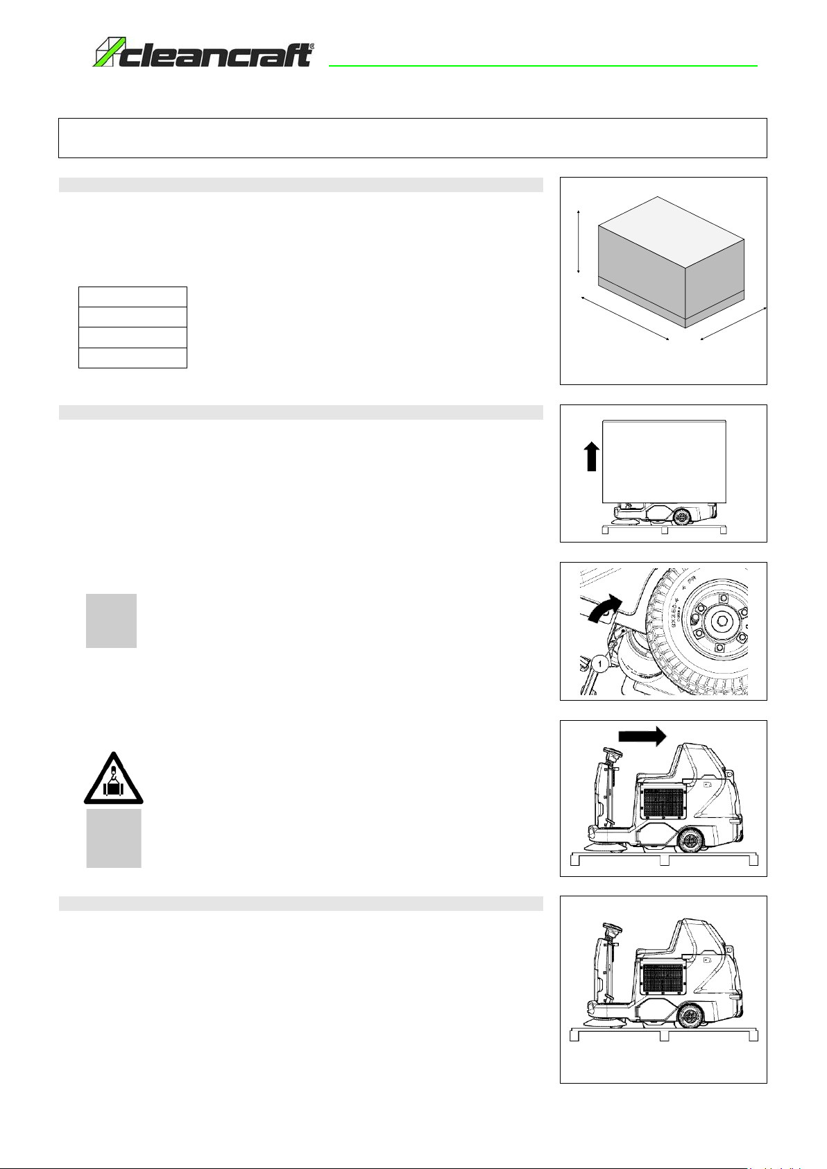
1. HANDLING OF THE PACKED MACHINE
The machine iscontained in specific packaging with a pallet for the handling with fork trucks. The
packages cannot be placed on top of eachother.
The total weight of the machine with its packaging is210 kg
The dimensions ofthe packaging are as follows:
A : 1270 mm
B : 1020 mm
C : 1760 mm
A
CB
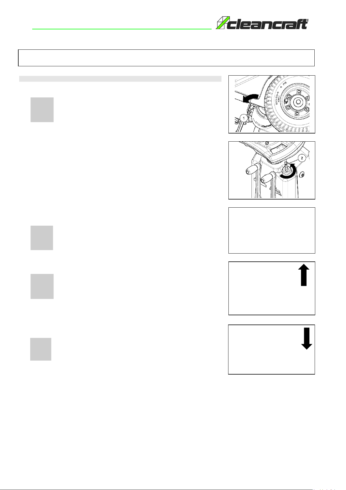
2. HOW TO UNPACK THE MACHINE
1. Remove the outer package.
2. Disengage theelectronic brake,turnthe lever (1) (onthe rear right-handsideof themachine)clockwise.
3. The machine is fixed to the pallet with wedges which block the wheels.Remove the wedges.
4. Use a chute to get themachine down from the pallet, pushing it backwards.
ATTENTION: Duringtransportation, the electrical brake should not be engaged, the
machine will in any event, if the critical speed threshold iscrossed, activate the
internal brakingsystem ofthe chopper circuit board and will emit a warning noise.
5. Keep the pallet for any future transport needs
WARNING: If the product is delivered in cardboard containers, handle the packed
product withsuitable lifting means thatcomply with the legal requirements
WARNING: During this operation, check there are no people or objects near the
machine
3. HOW TO MOVE THE MACHINE
1. Check that the central brush is lifted from the ground, otherwise lift it by moving the lever onthe rear
of the steering column.
2. Check that the side brush/es is/are lifted from the ground, otherwise lift it/them by moving the lever
on the rear of the steering column.
3. Place it on a pallet using a chute.
4. Check the main switch is in the “0” position, if this is not the case, turn the key by a quarter of a turn
to the left.
5. Remove the keyfrom the main switch.
6. Secure the machine to the pallet using wooden wedges.
7. Engage the electronic brake.
11

MACHINE PREPARATION
4. HANDLEBAR CONTROL COMPONENTS
The handlebar control components are identified as follows:
1. Level indicator for battery/hour meter.
2. Filter shaker control button.
3. Horn button.
4. Reverse button.
5. Vacuum motor "STOP" button.
5. STEERING COLUMN COMPONENTS
The steering column components are identified as follows:
1. Central brush lifting lever.
2. Lever for raising the side brush (1SL version) or brushes (2SL version).
3. Main key switch.
4. Emergency button.
6.FOOTBOARD COMPONENTS
The footboard components are identified as follows:
1. Drive pedal, accelerator pedal
2. Front flaplifting pedal
12
MACHINE PREPARATION
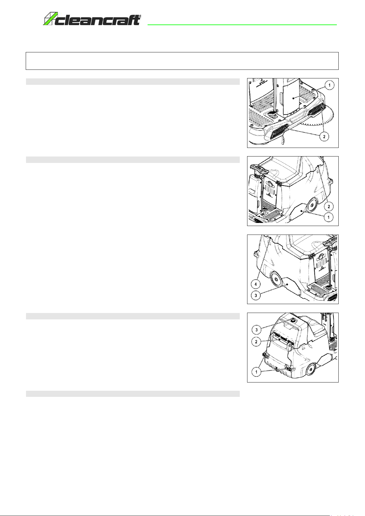
7.FRONT COMPONENTS
The front components ofthe machine are identified as follows:
1. Storage compartment.
2. Headlights.
8.SIDE COMPONENTS
The components on the side of the machine are identified as follows:
1. Left side panel central brush engage/adjustment.
2. Seat unit lifting handle.
3. Right side panel central brush maintenance.
4. Seat unit lifting handle.
9.REAR COMPONENTS OFTHE MACHINE
The rear components ofthe machine are identified asfollows:
1. Debris hopper retainer.
2. Debris hopper handle.
3. Blinking light (optional).
10. BATTERY TYPE
Power tothe machine must besupplied by sealed traction batteries withgas recombination or gel
technology. OTHER TYPES MUST NOT BE USED.
The batteries must meet the requirements laid out inthe norms: CEI EN60254-1:2005-12 (CEI 21-5) +
CEI EN60254-2:2008-06 (CEI 21-7)
The battery compartmentcan housetwo 12V batteries
For a good operating performance, we suggest the use of 105 Ah C5 batteries
13
MACHINE PREPARATION
11. BATTERY MAINTENANCE AND DISPOSAL
For informationabout battery maintenance, refer to the instructions provided by the battery manufacturer.
When the battery reaches the end of its working life, itmust be disconnected by expert, trained personnel,
then lifted (using the grips and suitable lifting devices) to remove it from the battery compartment.
EXHAUSTED BATTERIES ARE CLASSIFIED AS DANGEROUS WASTE ANDMUST BE
CONSIGNED TO THE AUTHORISEDBODIES FOR CORRECT DISPOSAL.
WARNING: you are advised to always wear protective gloves, to avoid the risk
of serious injury to your hands.
WARNING: You are advised to only lift and move the batteries with lifting and
transportation means suitable for the specific weight and size
12. FITTING THE BATTERIES INTO THE MACHINE
The batteries must be housed inthe appropriate compartment beneath the seat unit. They should be
handled using lifting equipment that issuitablein terms ofboth weight andcoupling system. They must
alsosatisfy the requirements of Standard CEI 21-5. The dimensions ofthebattery compartment are:
340 x174xH310 mm.
WARNING: For battery maintenance and daily recharging, you must carefully follow
the instructions provided by the manufacturer or retailer. All installation and
maintenance operations must be carried out by specialised personnel.
WARNING: Ensure that you comply with the accident prevention regulations inforce in
the country where you work or with DIN EN 50272-3 and DIN EN 50110-1, before any
handling of the batteries.
WARNING: To prevent an accidental short circuit use insulated tools to connect the
batteries, and do not place or drop metal objects on the battery. Remove rings,
watches and any clothing with metal parts that may come into contact with the battery
terminals.
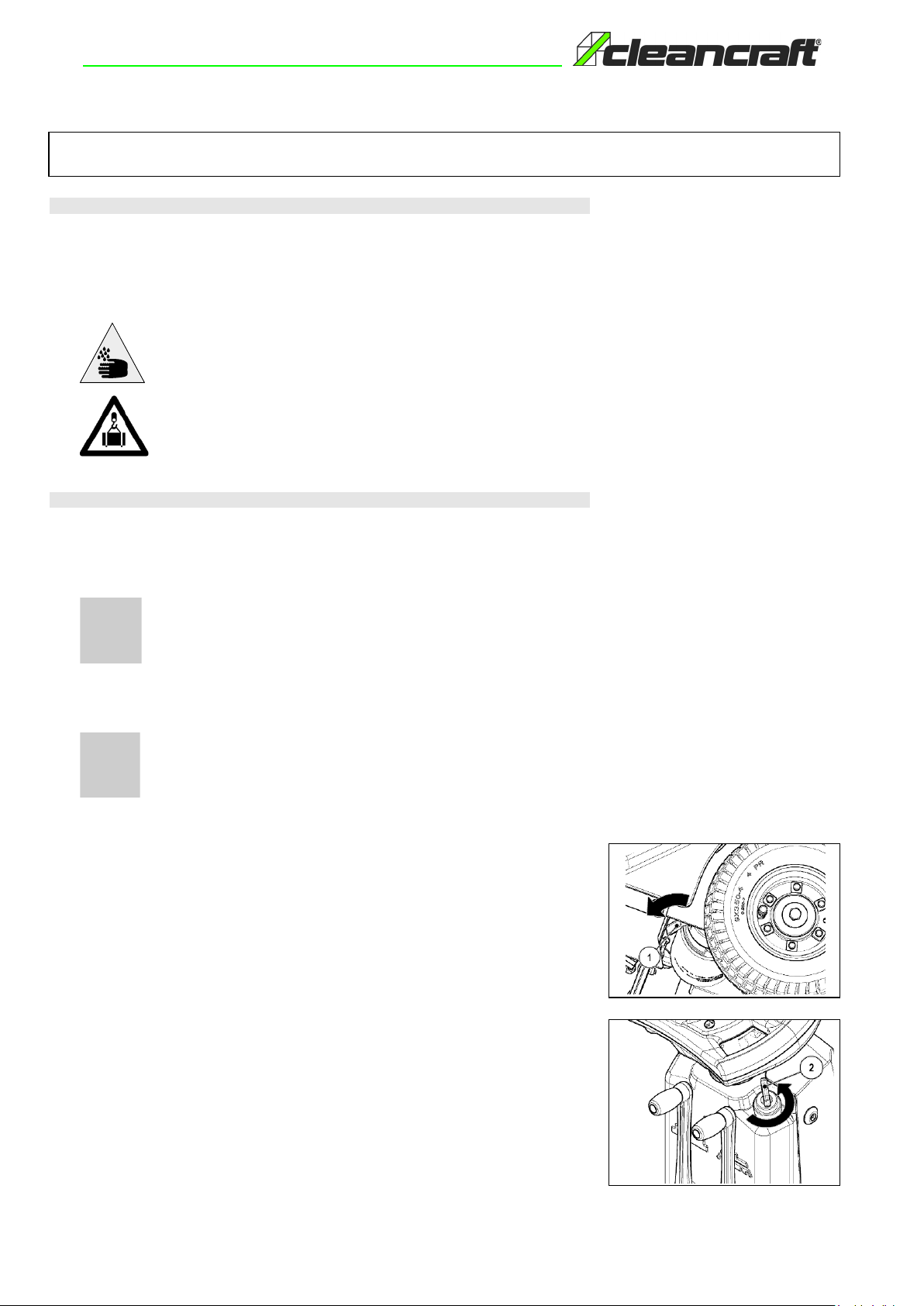
To insert the batteries into the compartment proceed as follows:
1. Makesure the electric brake is engaged, otherwise engage it using the lever (1) located at the left
rear of the machine (working direction).
2. Check the main switch (2) is in the “0” position, if this is not the case, turn the key by a quarter of a
turn tothe left, and remove the key from the instrument panel.
14
MACHINE PREPARATION
3. Grasp the handle located on the side of the operatorseat unit.
4. Lift the operator seat unit until the safety clamp (3) is hooked.
WARNING: Before installing the battery,clean the battery compartment with a damp
cloth. Check that the connectors on the cables supplied are functioning correctly.
WARNING: Check thatthe characteristics of the battery that you are lookingto use are
appropriate for the type of work to be performed. Check the battery charge and the
condition of the contacts on the battery.
WARNING: You are advised toonly lift and move the batteries with lifting and
transportation means suitable for the specific weight and size.
WARNING: The lifting hooks must not damage the blocks, connectors or cables.
5. House the batteries in the compartment, positioningthe poles “+” and“-“ opposite each other.
WARNING: Before inserting the batteries into the machine, remember tocover the
terminals witha little grease to protect them against external corrosion.
WARNING: You are advised to use airtight batteries only, to avoidthe leakage of acids!
WARNING: You are advised to always wear protective gloves, to avoid the risk of
serious injury to your hands.
15
13. CONNECTING THE BATTERIES AND BATTERY CONNECTOR
To connect the batteries proceed as follows:
1. Connect the batteries in series to the "+" and "-" poles using the supplied jumper cable (1).
2. Connect the battery connector cable to the "+" and "-" poles in order to obtain theterminal voltage
of 24V.
3. Connect the electric system connector (3) to the battery connector (2).
WARNING: All installation andmaintenanceoperations must becarried out by expert
personnel, trained atthe specialised assistance centre.
WARNING: you are advised to always wear protective gloves, to avoid the risk of
serious injury to your hands.
2
1
3
MACHINE PREPARATION
14. BATTERY CHARGER CONNECTION
In order not tocause permanent damage to the batteries, itisessential to avoid their complete discharge:
arrange the recharge within a few minutes of the switchingon of the "discharged batteries" blinkinglight.
WARNING: Never leave the batteries completely discharged, even if the machine is not
being used. Check the battery charger is suitable for the batteries installed, in terms of
both capacity and type.
To connect the battery charger you must:
1. Movethe machine to theplaceused for maintenance or recharging the batteries.
2. Make sure the electric brake is engaged, otherwise engage it using the lever (1) located at the left
rear of the machine (working direction).
3. Check the main switch (2) is in the “0” position, if this is not the case, turn the key by a quarter of a
turn tothe left, and remove the key from the instrument panel.
4. Grasp the handle located on the side of the operatorseat unit.
5. Lift the operatorseat unit until thesafety clamp (3) is hooked.
WARNING: Park the machine in an place protected from the weather andwith suitable
ventilation, and on aflat and levelsurface; near the machine there must be no objects
that could either damage it, or be damaged through contact with it.
6. Disconnect the electric system connector (4) from the battery connector (5).
ATTENTION: this process must becarried out by qualified personnel. An incorrect
connection of the connector may cause problems with machine functioning.
16
7. Connect the battery charger cable (6) to the battery connector (5).
WARNING: Keep the seat unit open for the duration of the battery recharging cycle to
allow gas fumes to escape.
WARNING: The room used to recharge the batteries must be adequately ventilated to
prevent the accumulation of gases that leak from batteries.
The coupling connector of the battery charger is supplied insidethe bag containingthis instruction
booklet, and must be fitted tothe battery charger cables asshown inthe instructions.

MACHINE PREPARATION
8. Connect the recently wired cable to the external battery charger.
WARNING: Carefully read the use and maintenance instructions of the battery charger
that is used for charging.
WARNING: Danger of gas exhalation and leakage of corrosive liquids.
WARNING: Danger of fire: donot go near with free flames
9. When the recharge cycle is complete, disconnect the battery charger connector from theexternal
battery charger.
10. Disconnect the battery charger cable (6) from the battery connector (5).
11. Connect the battery connector (5) to the electricsystemconnector (4).
12. Grasp of the handle locatedon the side of the operator seat unit and lower the seat unit until it is in
the working position.
15. BATTERY CHARGER CONNECTION
In order not tocause permanent damage to the batteries, itisessential to avoid their complete discharge:
arrange the recharge within a few minutes of the switchingon of the "discharged batteries" blinkinglight.
WARNING: Never leave the batteries completely discharged, even if the machine is
not beingused. Check the battery charger is suitable for the batteries installed, in
terms of both capacity and type.
17

MACHINE PREPARATION
To connect the battery charger you must:
1. Movethe machine to theplaceused for maintenance or recharging the batteries.
2. Makesure the electric brake is engaged, otherwise engage it using the lever (1) located at the left
rear of the machine (working direction).
3. Check the main switch (2) is in the “0” position, if this is not the case, turn the key by a quarter of a
turn tothe left, and remove the key from the instrument panel.
4. Grasp the handle located on the side of the operator seat unit.
5. Lift the operatorseat unit until thesafety clamp (3) is hooked.
WARNING: Park the machine in an place protected from the weather andwith suitable
ventilation, and on aflat and levelsurface; near the machine there must be no objects
that could either damage it, or be damaged through contact with it.
6. Remove the battery charger cover (4).
7. Connect the battery charger power cable connector tothe socket on the charger itself.Before
inserting the power cable into the socket of the charger, verify that there isno condensate or other
forms of liquids.
8. Plug the battery charger powercable into the mains socket.
WARNING: Carefully read the use and maintenance manual of thecharger that is
delivered inside the bagcontaining this instruction booklet.
WARNING: Keep the seat unit open for the duration of the battery recharging cycle to
allow gas fumes to escape.
WARNING: The room used to recharge the batteries must be adequately ventilated to
prevent the accumulation of gases that leak from batteries.
9. When the recharge cycle is complete, disconnect the battery charger cable from the mains.
10. Disconnect the battery charger power cable connector from the socket on the charger itself.
11. Replace the battery charger cover (4).
12. Grasp of the handle locatedon the side of the operator seat unit and lower the seat unit until it is in
the working position.
WARNING: if the machine's electric system is accidentally powered (by turningthe
main switch to "I"), the commands display will show “BATTERY-CHARGER” and no
steering wheel command will function.
WARNING: Always make sure the green LED of the battery charger is on before using
the machine again.
4
4
18
MACHINE PREPARATION
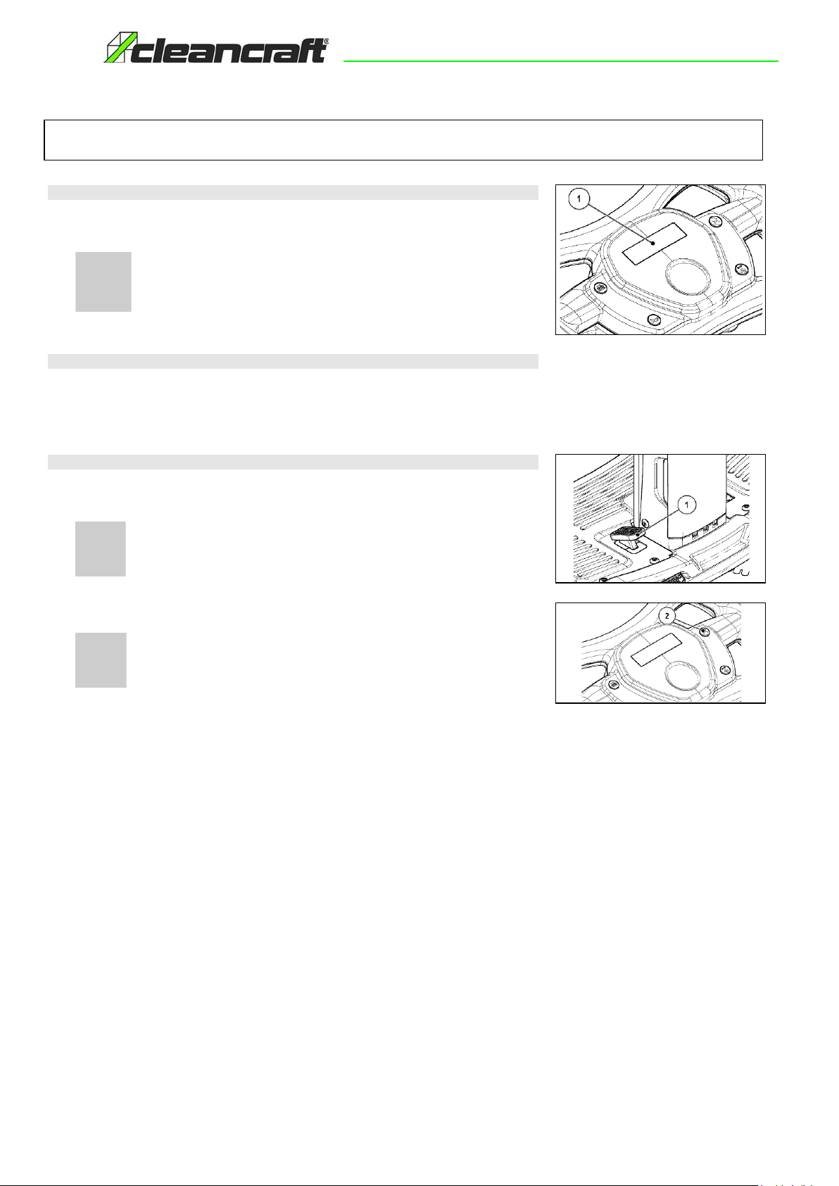
16. BATTERY CHARGELEVEL INDICATOR
On the instrument panel of themachine thereis a monitor (1) indicating(amongst other things) the battery
charge status. If the lower linecontains ten light indicators, the battery charge level is 100%. If the battery
charge percentage is at 00% and flashing, this means thebatteries are discharged.
WARNING: After a fewseconds that the battery charge has reached 20%,the central
brush motor, the side brush/es motor, and the vacuum motor will turn off
automatically.With theremainingcharge, it is still possible, however, to move the
machine to the location designated for rechargingthe batteries.
17.HOUR METER
On the machine's instrument panel there is a display (1) indicating the total machine usage time. The top
line shows the hoursandminutes offunctioning. Theflashing “:” symbol Indicates that the hour meter is
countingthe machine functioning time.
18.WORKING FORWARD SPEED
This machine is equipped withelectronic traction control. To move the machine, after having turned the
key in the "I" position, push the drive pedal (1) adjusting thespeed by pressing and releasing the pedal.
The machine will then start moving.
ATTENTION! The machine will not start to move (eitherforwards or backwards) if the
electrical brake is not engaged. In this case, you will see"ELECTRICAL BRAKE?" on
the command display.
To move the machine backwards, press the button (2) on the instrument panel, then immediately press
the pedal (1). Adjust the speed by altering the degree of pressure onthe pedal.
WARNING! The reverse speed is lower than the forward speed to comply with current
health and safety standards.
19
19.BLINKING LIGHT (OPTIONAL)
The machinecan be equipped with ablinking light that turns onautomatically when the key inthe main
switch is turned on.
20. HEADLIGHTS
The machine has headlights that turn on automatically when the main switch is turned to "I" or "II".
PREPARING TO WORK
21. PREPARING TOWORK
Before beginning to work, itisnecessary to:
1. Ensure that the debris hopper is empty, otherwise empty it completely (see paragraph "EMPTYING
THE DEBIT HOPPER").
2. Check that the condition of the central brush is suitable for the work, otherwise arrange for its
maintenance (see paragraph "CLEANING THE BRUSH CENTRAL" or "CENTRAL BRUSH
REPLACEMENT").
3. Check that the condition of the side brush (version 1SL or brushes version 2SL) is suitable for the
work, otherwise arrange for their maintenance (see paragraph "CLEANING THE SIDE BRUSH" or
"SIDEBRUSHREPLACEMENT").
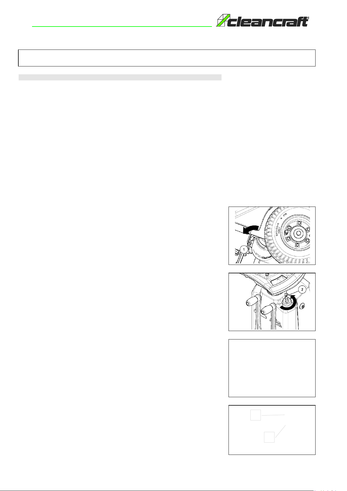
4. Makesure the electric brake is engaged, otherwise engage it using the lever (1)located at the left
rear of the machine (working direction).
5. Check the main switch (2) is in the “0” position, if this is not the case, turn the key by a quarter of a
turn tothe left, and remove the key from the instrument panel.
6. Makesure the emergency switch is in the OFF position.
7. Grasp the handle located on the side of the operatorseat unit.
8. Lift the operatorseat unit until thesafety clamp (3) is hooked.
9. Connect the machine connector (4) to the battery connector (5).
10. Grasp of the handle locatedon the side of the operator seat unit and lower the seat unit until it is in
the working position.
4
5
20
This manual suits for next models
1
Table of contents
Other CleanCraft Blower manuals


