Clear-Com XLR-7M User manual

XLR-7M Option
FittingInstructions
Fitting an XLR-7M Headset Connector Assembly
Fitting Instructions for XLR-7M PCB Assembly
These instructions are for fitting an XLR-7M connector to 1 RU, 2 RU rackmount and
desktop V-Series panels that are already fitted with male XLR-4M headset
connectors. They do not apply to panels fitted with female headset connectors.
Converting the XLR-4M to XLR-7M requires the following items:
1 x XLR-7M Headset Connector Assembly part no. 770129Z
1 x XLR-7M fitting instructions part no. 810405Z (this document)
Tools Required
•
1 x No. 1 Pozidrive screwdriver
•
1 x electricians flat blade screwdriver (Approximately 3mm tip width)
•
1 x 5mm nut spinner
1
PN 810405Z Rev. C

V-Series XLR-7M Option .
Fitting the XLR-7M Headset Connector Assembly to Rack Mount Panels
Before fitting the XLR-7M Headset Connector Assembly the panel must be
completely disconnected and removed from any rack or console. Place the panel on
a clear workspace suitable for antistatic precautions.
Step 1
The power supply should be removed from the cradle at the back of the panel if it has
been fitted there (see Figure 1). If it is not fitted in the cradle proceed to step 2.
Figure 1: Power Supply in Cradle on Rack Mount Panel
Unlock the power connector from the panel by turning the outer ring anticlockwise
then pulling the connector. Remove the power supply block by pulling it out of the
rear of the cradle (Figure 2).
Step 2
Figure 2: Panel with Power Supply Removed
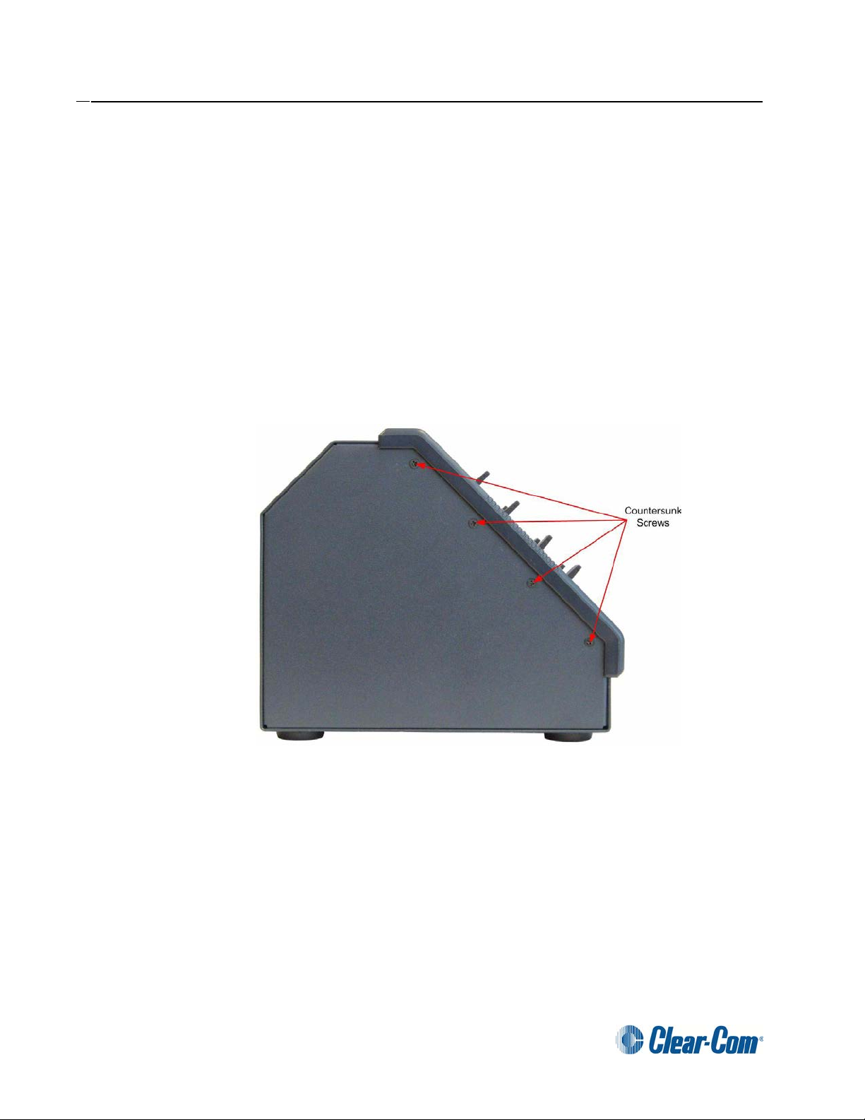
The next step is to remove the four countersunk screws and four panhead
screw and washer assemblies holding thelidon. Thecountersunk screws are
located on the top of the lid,two of the panhead screw and washer assemblies
2.
PN 810405Z Rev. C

. V-Series XLR-7M Option
are located on the rear of the panel and one at each end of the panel (Figure
3). Ensure that all the screws are retained for refitting the lid.
Figure 3: Remove Screws from Panel Lid
Remove the lid from the panel.
Step 3
If the panel is a 1-RU panel then the front panel assembly must be removed to gain
access to change the headset connector. If the panel is a 2-RU panel then the front
panel assembly need not be removed.
If the front panel does not need to be removed omit steps 4 and 5.
Step 4
Remove the 2 encoder knobs from theMain and Aux level controls. These simplypull
off the shafts.
Remove the countersunk screws from the rear of the left and right mounting ears.
Figure 4: Mounting Ears on 1-RU Panel
3 PN 810405Z Rev. C

V-Series XLR-7M Option .
Step 5
Remove the four countersunk screws from the bottom of the chassis (located along
the bottom front edge).
Figure 5: Screws on Bottom of Chassis
Pull the front panel assembly away from the chassis to give access to the connectors
and cables.
Step 6
Disconnect the microphone and main board connection cables from the Front Panel
Audio Card. Disconnect the cable from the Headset Connector Assembly.
Figure 6: Cable Removal from Audio Card
PN 810405Z Rev. C 4.

. V-Series XLR-7M Option
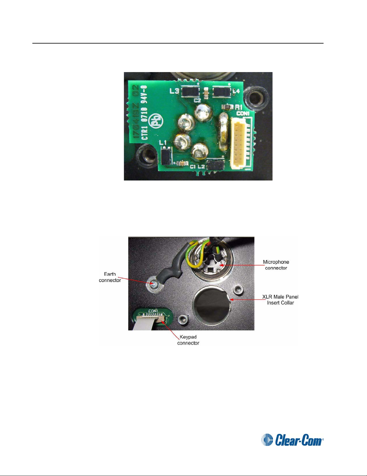
Figure 7: Audio Card with Cables Removed
Remove the 2 Pozidrive screws from the Front Panel Audio Card and gently pull the
audio card away from the Headset Connector Assembly.
Step 7
Remove the2hexpillarssecuringtheHeadsetConnectorAssemblytothefrontpanel
assembly using the 5mm nut spinner.
Figure 8: Audio Card Removed from Headset Connector Assembly
5 PN 810405Z Rev. C
V-Series XLR-7M Option .
Step 8
Figure 9: Headset Connector Assembly with Hex Pillars Removed
Remove the existing XLR-4M Headset Connector Assembly from the front panel
assembly.
Figure 10: Panel with Headset Connector Assembly Removed
PN 810405Z Rev. C 6.

. V-Series XLR-7M Option
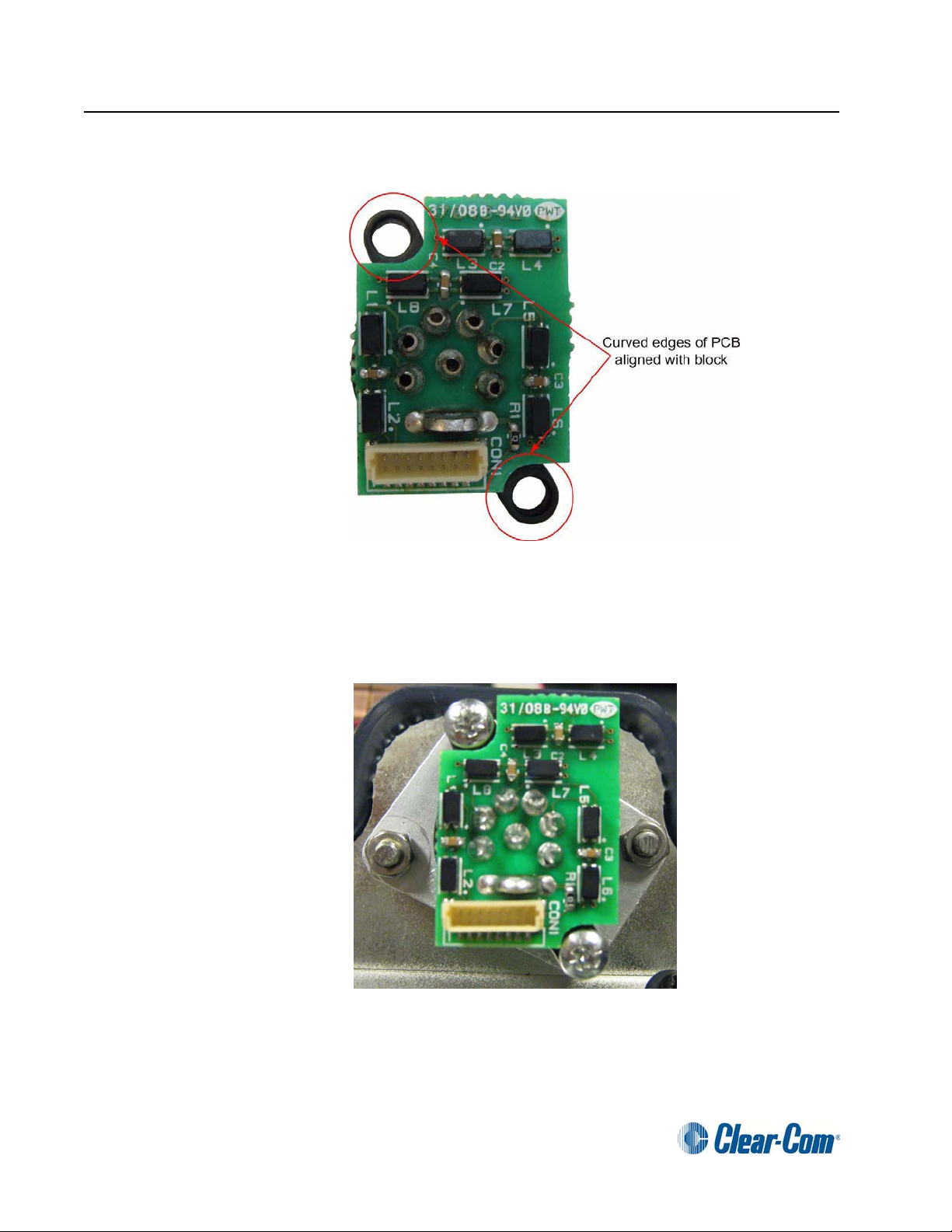
Step 9
Before fitting the XLR-7M Headset Connector Assembly it should be checked to
ensure that the PCB is aligned so that the hex pillars will clear the PCB when they are
in place.
If the assembly requires adjustment please refer to Appendix A.
Figure 11: XLR-7M Assembly Alignment
Fit the XLR-7M Headset Connector Assembly onto the front panel as shown in Figure
12.
7 PN 810405Z Rev. C


V-Series XLR-7M Option .
Step 12
If the grub screw is loose turn the grub screw clockwise as shown in Figure 15 below
until the assembly is rigid.
Warning: The grub screw in the XLR connector has a left hand thread; when
this is turned clockwise the grub screw will move out of the connector and lock
with the black plastic moulding. Do not over tighten the grub screw as this is
very difficult to refit once the PCB is assembled.
Figure 15: Tightening XLR-7M Grubscrew
When the XLR-7M Headset Connector Assembly has been fitted the front view is
shown in Figure 16.
Figure 16: Front View of XLR-7M Headset Connector Assembly Fitted
PN 810405Z Rev. C 10.

. V-Series XLR-7M Option
Step 13
To reassemble the panel carry out the following steps:
•
Refit the 2 Pozidrive screws from the Front Panel Audio Card.
•
Reconnect the cable to the Headset Connector Assembly.
•
Reconnect the microphone and main board connection cables to the
Front Panel Audio Card.
If the panel front assembly has been removed the following steps must be carried out
to reassemble the panel:
•
Locate the front panel assembly back onto the chassis.
•
Ensure that no cables are trapped between the front panel assembly
and the chassis before fitting the screws.
•
Refit the countersunk screws to the rear of the mounting ears.
•
Replace the four countersunk screws on the bottom of the chassis.
•
Refit the 2 encoder knobs to the Main and Aux level controls.
Step 14
To complete the reassembly of the panel:
Screw the lid back on the panel making sure that the correct screws are used
(see Figure 3). Refit the four panhead screw and washer assemblies first and
then the four countersunk screws.
Figure 17: Reassembled Rack Mount Panel
If the power supply was originally held in the cradle replace it in the cradle and
reattach the power supply cable to the power inlet (see Figure 1).
Remount the panel in the rack or console and reconnect power and I/O
cables.
11 PN 810405Z Rev. C
V-Series XLR-7M Option .
Fitting the XLR-7M Headset Connector Assembly to Desktop Panels
Before fitting the XLR-7M Headset Connector Assembly the panel must be
completely disconnected from any cabling. Place the panel on a clear
workspace suitable for antistatic precautions.
Step 1
Note: Record whether the panel has been build for desktop use or for
attachment to a wall to ensure the front panel is replaced in the correct
orientation.
Remove the eight countersunk screws holding the front of the panel on. The
countersunk screws are located on the ends of the panel, four on each end
(Figure 18).
Figure 18: Desktop Panel Retaining Screws
Remove and retain all the screws and remove the front panel assembly. The
cables connecting the front panel electronics to the main PCB are long
enough to allow the panel front to be removed without having to unplug any of
the cables.
PN 810405Z Rev. C 12.

. V-Series XLR-7M Option
Step 2
The Headset Connector Assembly secured to the mounting block by two
pozidrive screws at the top of the front panel assembly.
Figure 19: Desktop Front Panel Assembly with XLR-4M Fitted
•
Remove the audio card cable.
•
Remove the two pozidrive screws securing the Headset Connector
Assembly to the mounting block.
•
Remove the Headset Connector Assembly.
Step 3
Before fitting the XLR-7M Headset Connector Assembly it should be checked to
ensure that the PCB is aligned so that the pozidrive screw heads will clear the PCB
when they are in place.
If the assembly requires adjustment please refer to Appendix A.
Note: The grubscrew should not be loose when fitting the Headset Connector
Assembly to the mounting block.
13 PN 810405Z Rev. C
V-Series XLR-7M Option .
Figure 20: Headset Connector Assembly Alignment
Position the XLR-7M Headset Connector Assembly on the mounting block and
replace the two pozidrive screws.
Step 4
Figure 21: XLR-7M Headset Connector Assembly Attached to Mounting Block
Replace the audio card cable in the Headset Connector Assembly.
PN 810405Z Rev. C 14.
. V-Series XLR-7M Option
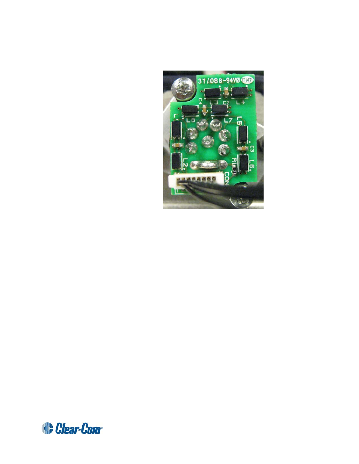
Step 5
Figure 22: XLR-7M Headset Connector Assembly with Audio Card Cable
Replace the front panel assembly ensuring it is replaced in the correct
orientation noted in step 1, making sure that the correct screws are used (see
Figure 18).
Insert the microphone connector edge into position first, then lower the
headset connector into place.
Note: Ensure that no cables are trapped before attempting to refit the
screws.
Apply pressure to the lid to align the screw holes and fit the top and bottom
screwsloosely on each side before fitting the remaining screws and tightening
all the screws.
Re-site the panel and reconnect power and I/O cables.
15 PN 810405Z Rev. C
V-Series XLR-7M Option .
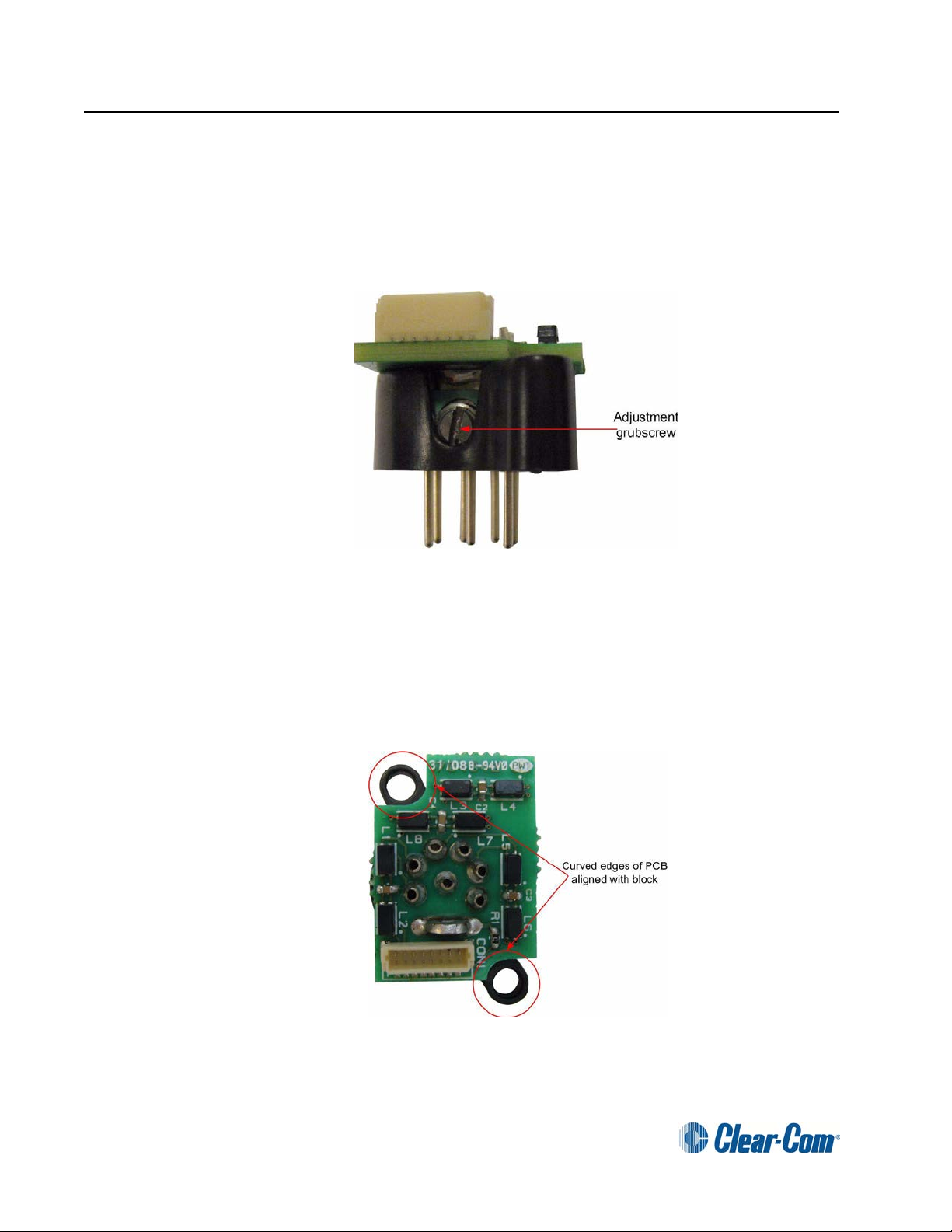
Appendix A Headset Connector Assembly Adjustment
In order to align the PCB correctly with the block the grubscrew should be loosened
before adjusting the Headset Connector Assembly. This is done by turning the
grubscrew anticlockwise to loosen the PCB from the block.
Figure 23: Grubscrew in Headset Connector Assembly
Adjust the PCB position to centralize the curved PCB edges with respect to the holes
in the block and then retighten the grub screw by turning it clockwise.
Warning: The grub screw in the XLR connector has a left hand thread; when
this is turned clockwise the grub screw will move out of the connector and lock
with the black plastic moulding. Do not over tighten the grub screw as this is
very difficult to refit once the PCB is assembled.
Figure 24: XLR-7M Assembly Alignment
PN 810405Z Rev. C 16.
Table of contents
Other Clear-Com Cables And Connectors manuals


