ClearCount SmartSponge User manual


i
Preface
Indications for Use
The ClearCount Medical Solutions SmartSponge® System is indicated for use in
counting and recording the number of RFID-tagged surgical sponges, laparatomy
sponges, and towels used during surgical procedures. It also provides a non-invasive
means of locating retained radio-frequency identification (RFID)-tagged surgical
sponges, towels, and other tagged items within a surgical site.
Warnings
The following list of warnings applies to the SmartSponge System:
•Use only one SmartSponge System during a surgical procedure.
•Do not use the system in the presence of a flammable anesthetic mixture with air, or
with oxygen or nitrous oxide.
•For the system to function, use only ClearCount disposables.
•Keep the SmartSponge System outside of the sterile field, unless it is properly
covered.
•Place only ClearCount disposables in the SmartBucket.
•The sterility of disposables is guaranteed only for unopened, undamaged packages.
Disposables are for single use only; do not re-use or re-sterilize disposables.
•Do not cut or tear SmartSponge disposables, as the RFID tags might become
separated.
•When scanning items contained in a surgical kit (bundles of items not in their own
sterile packages) into the SmartSponge System, cover the head of the system with
the sterilized bucket liner from the surgical kit. This prevents non-sterile
contamination of the items being scanned in.
•Using the scanning wand without a sterile wand cover could contaminate the sterile
field.
•Holding items close to the SmartBucket may result in items being added to the Count
Out column prior to disposal. Dispose of any items into the SmartBucket without
using them if the Count Out Bucket has detected them prior to use.
•Disposables should not be left inside the patient’s body for more than 24 hours.
•Do not subject patients to an MRI with SmartSponge disposables still inside the
patient.
•Tags may become damaged by surgical lasers. Do not apply a surgical laser directly

ii
to a tag. The loss of tag function may result.
•Due to possible interference, the system should be separated by at least 1 meter from
an active Electrosurgical Unit (ESU). The system should be checked for normal
operation to ensure there is no interference present.
•Do not dispose of packed sponges from a previous surgical case into the
SmartBucket. Sponge counts may not reconcile properly.
•No part of the ClearCount SmartSponge System is user serviceable. The system
contains no user replaceable fuses. All Service is to be performed by trained
personnel.
Conventions Used
Warning!
A warning is a statement that identifies conditions or actions that could result in personal
injury or loss of life.
Caution!
A caution is a statement that identifies conditions or actions that could result in damage
to the system.
Note
A note is an advisory comment or recommendation regarding practices or
procedures.

SECTION
PAGE
Preface ............................................................................................................................ i-ii
Chapter 1:System Description .......................................................................................1-1
Count In Scanner...............................................................................................1-1
Count Out Bucket & Wand Components...........................................................1-2
Display & Function Control Buttons...................................................................1-4
SmartSponge Disposables................................................................................1-6
SmartTags.........................................................................................................1-8
SmartWand........................................................................................................1-9
Wand Cover.....................................................................................................1-10
Override Card..................................................................................................1-10
Chapter 2: Initial Setup & Operation ...............................................................................2-1
Powering on the SmartSponge System.............................................................2-2
Placing the SmartTag........................................................................................2-3
Boot-up Screens................................................................................................2-4
Standby Mode....................................................................................................2-6
Setting Up for Surgery.......................................................................................2-7
Count Mode Operation ......................................................................................2-8
Scanning Items Into and Out of Surgery..........................................................2-10
Requesting Final Item Count Reports..............................................................2-11
Wand Mode Operation ....................................................................................2-14
Restoring Power..............................................................................................2-18
Chapter 3: Cleaning and Maintenance............................................................................3-1
Cleaning Instructions.........................................................................................3-2
Maintenance......................................................................................................3-3
Chapter 4: Troubleshooting.............................................................................................4-1
General Troubleshooting...................................................................................4-2
System Alerts.....................................................................................................4-4
System Warnings ..............................................................................................4-6
System Failure...................................................................................................4-7
Appendix: Technical Specifications................................................................................5-1
SmartSponge System Dimensions....................................................................5-1
Power Requirements.........................................................................................5-2
Environmental Conditions..................................................................................5-2
EMC Considerations..........................................................................................5-3
Device Label......................................................................................................5-8
1-1
•
•
•
•
•
•
• • • • • •
Chapter 1: System Description
The SmartSponge® System is used in an operating room to detect and identify tagged surgical items for the
purpose of reconciling surgical counts. The system employs radio-frequency identification (RFID) technology
to detect ClearCount SmartSponge surgical sponges and towels. The system combines the benefits of counting
and detection of surgical items (sponges, gauze, and towels) used during a surgical case. It has a user-friendly
color display that provides detailed item counts. The counts are automatically updated as SmartSponge RFID-
tagged sponges and towels are scanned “in” and “out” of the surgical procedure.
This chapter includes a brief overview of the system and a detailed description of its components.
System Components
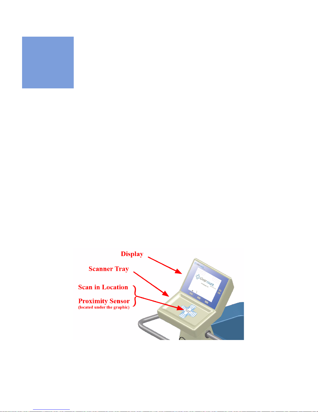
Count In Scanner
The Count In Scanner, shown in Figure 1-1, is used to count items into the surgical case prior to using the
items. The Count In Scanner is located below the area marked
Touch Here to Scan.
The proximity sensor
activates the Count In Scanner when sponges are present. As surgical sponges and towels are placed on the
Count In Scanner, it adds the tagged items to the In-Scan Inventory. This inventory or quantity of scanned-in
items appears in the
IN
column of the Count Mode screen on the display. Table 1-1 lists the scanner
components.
Figure 1-1 Count In Scanner Components

Chapter 1: System Description - System Components 1-2
•
•
•
•
•
•
Count Out Bucket and Wand Components
The Count Out Bucket detects the RFID-tagged sponges and towels discarded into it during a surgical case.
The Handle and Casters contribute to the mobility of the SmartSponge System. The Handle is strategically
located to protect the Count In Scanner from forcefully hitting a wall, while also providing the user with a
comfortalbe means of manuvering the system. The two rear casters are able to be locked in place to keep the
system stable during use. The Power Entry and On/Off Switch are located at the back of the system near the
floor. The power cord will be inserted into the Power Entry and then switched to On to begin. When not in use,
the SmartWand is mounted to the rear of the system by means of the Wand Holder; and the wand’s cord is
retained on the SmartWand Cord Wrap. See Figure 1-2.
Table 1-1 Count In Scanner Components
Component Description
Scanner Tray The area on which sponges and towels are
to be placed when scanning them into a
surgical case.
Proximity Sensor This sensor detects the presence of items
introduced to the Scan In Location
automatically activating the Scanner Tray.
Display Displays updated information for the user to
track sponge counts throughout the surgical
procedure. Also displays various modes of
operation.
Scan In Location The location on the Scanner Tray to scan
sponges and towels into the surgical case.
The Proximity Sensor is also located here
under the
Touch Here to Scan
label.

1-3
Chapter 1: System Description
-
System Components
•
•
•
•
•
•
Figure 1-2 Count Out Bucket Components
Table 1-2 Count Out Bucket Components
Component Description
Handle Used to move the SmartSponge System.
Also positioned to protect the Count In
Scanner and display from damage.
Count Out Bucket Scans out and contains the discarded
sponges and towels after their use in
surgery.
Wand Holder Used to mount the SmartWand to the
SmartSponge System when not in use.
SmartWand Cord Wrap Keeps the SmartWand’s cord retained while
the wand is mounted to the SmartSponge
System.
SmartWand Used to detect sponges. This is done by
scanning the patient with the SmartWand.
Power Entry and On/Off Switch The Power Entry connects the SmartSponge
System to a 120 VAC power source via the
power cable. The On/Off switch toggles the
power to the system.
Locking Casters Secures the postion of the SmartSponge
System.
Chapter 1: System Description - System Components 1-4
•
•
•
•
•
•
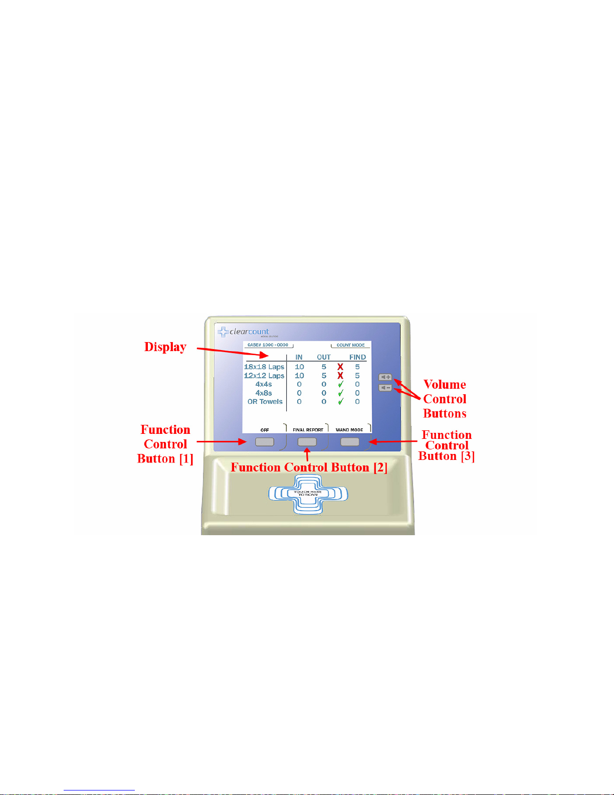
Display and Function Control Buttons
The display, function control buttons, and volume buttons are the user’s interface to the SmartSponge System.
This backlit display shows the following types of screens at various points, depending on the mode of
SmartSponge System operation:
•
Starting, Boot, and Power & Diagnostic screens (during system boot-up)
•
Standby, Ready to Count or Continuing case, and Count Mode
•
Final Report: Counts Equal, or Final Report: Counts Not Equal
•
Wand Mode
Each screen defines the operation of the control buttons for the associated mode of operation. There are three
function control buttons along the bottom of the display and two volume control buttons to the right of the
display. Figure 1-3 shows the location of the control buttons in relation to the example screen
Figure 1-3 Display and Control Buttons

1-5
Chapter 1: System Description
-
System Components
•
•
•
•
•
•
Table 1-3 Display/Controls
Display / Controls Description
Display LCD that provides information to the user
regarding operation of the system.
Volume Control Buttons These up and down buttons control the
volume of the audible alert. The Volume of
the alert can be set to four different levels
and off with each button.
Function Control Button [1] Allows the following actions;
On
- Turns
the system on from Standby Mode.
Off
-
Returns the system to Standby Mode.
Function Control Button [2] Allows;
Final Count
- Exits Count Mode
and proceeds to a final count screen for
verification before ending a case.
Back
-
Lets the user exit the final count screen and
return to Count Mode.
Function Control Button [3] Allows;
Wand Mode
- Switches from
Count Mode to Wand Mode.
Count Mode
-
Switches Back from Wand Mode to Count
Mode.
OverRide
- Allows the user an
option to end a case without reconciling the
sponge counts with an Admin Card.
End
Case
- Ends case and returns to standby.

Chapter 1: System Description - System Components 1-6
•
•
•
•
•
•
SmartSponge Disposables
The SmartSponge System utilizes surgical sponges and towels that have been “tagged” with an RFID
identification device. This RFID tag is smaller than a dime and does not contain a battery. Because each sponge
contains a tag with unique identification, the SmartSponge system can quickly and accurately count and
identify each sponge.
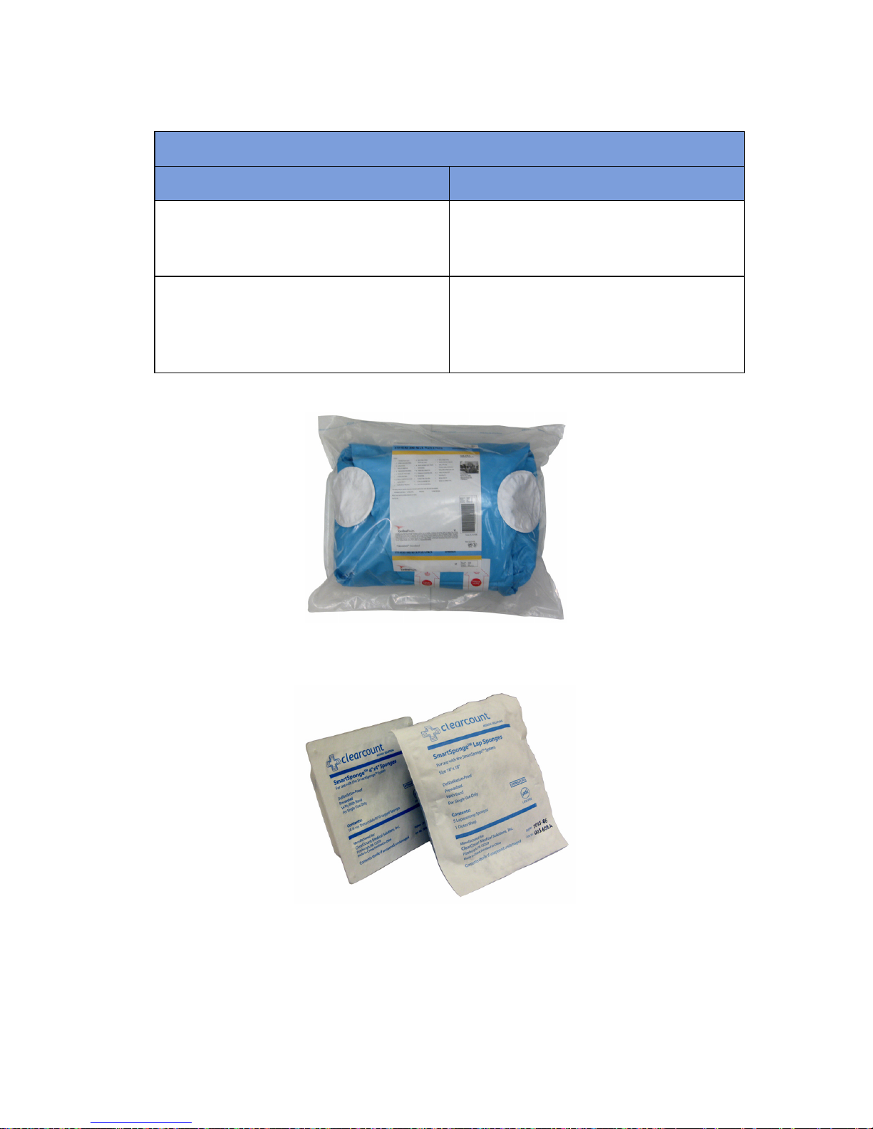
Surgical sponges are provided for surgery in two forms: pre-packaged surgical kits (Figure 1-4) and individual
sterile packages (Figure 1-5). There are different procedures involved when using one presentation versus the
other. Refer to Chapter 2 of this manual for further details.
Additionally, the SmartSponge System relies on several accessories for proper use and patient care. These
accessories are described briefly in Table 1-4.
Table 1-4 SmartSponge Disposables and Accessories
Accessory Description
Surgical Kits A pre-packaged kit of materials and
equipment assembled for a specific surgery.
Included are various banded packs of
SmartSponges for use with the
SmartSponge System.
Sterile Packages SmartSponges packaged by type for use
with the SmartSponge System that are not
pre-packaged in Surgical Kits.
Bucket Liner A large drawstring plastic bag used to
protect the Count Out Bucket from
contamination as soiled sponges are
discarded.
Wand Cover A large, sterile, clear plastic sheath used to
protect the sterile field when using the
SmartWand. The sheath covers the wand
and a portion of the wand cord.
1-7
Chapter 1: System Description
-
System Components
•
•
•
•
•
•
Figure 1-4 Example of Surgical Kit
Figure 1-5 Example of Sterile Sponge Packages
Override Card A Smart Card used by the appropriate staff
member to enable an unreconciled case to
be closed.
SmartTag A sticker applied between the sheets of the
OR table prior to surgery, which allows the
user to ensure that the SmartWand is
operational.
Table 1-4 SmartSponge Disposables and Accessories
Accessory Description

Chapter 1: System Description - System Components 1-8
•
•
•
•
•
•
Smart Tags
SmartTags are passive RFID labels that have an adhesive backing. See Figure 1-6. Prior to surgery, a SmartTag
is positioned under the surgical site between the sheets on the OR table. Figure 1-7 shows a typical position of
the SmartTag on the OR table.
This tag, working together with the SmartWand, provides feedback to the system that the SmartWand has
scanned through the depth of the patient’s body. The SmartTag provides notification that the scan is proceeding
properly, reducing the possibility of user error. The user can thus quickly identify SmartSponges that remain
in the patient.
Figure 1-6 SmartTag
Figure 1-7 Location of SmartTag on OR Table

1-9
Chapter 1: System Description
-
System Components
•
•
•
•
•
•
SmartWand
The SmartWand provides a fast and accurate patient scan for retained sponges. The handle of the circular
shaped wand, shown in Figure 1-8, has two LEDs to give the operator feedback from the scan.
The Green LED will begin to blink when
WAND
Mode is entered. When the SmartWand detects the presence
of a SmartTag the Green LED will stay illuminated; this also triggers a notification on the display. If the wand
detects a sponge that is retained inside a patient, the Red LED on the wand flashes, and the Wand Mode screen
displays the type and quantity of the item(s) found.
To use the wand, first remove it from the wand holder and pass it into the sterile field by means of the Sterile
Wand Cover. Next place the system intoWand Mode. The user then holds the wand by its handle and passes it
over the patient maintaining a distance of 1 to 3 inches above the body. As illustrated on the display, complete
five sweeps over the patient at a rate of 0.2m/sec. This helps to ensure complete coverage is achieved.
Figure 1-8 SmartWand
Table 1-5 SmartWand
Component Description
Red & Green LEDs Illuminate when the SmartWand detects a
SmartSponge (red) or a SmartTag (green).
SmartWand Cord Provides power to the SmartWand while
also allowing it to communicate with the
SmartSponge System.
SmartWand Handle Used to hold the SmartWand while
performing the patient scan.

Chapter 1: System Description - System Components 1-10
•
•
•
•
•
•
Wand Cover
A sterile wand cover is used when the patient needs to be scanned with the SmartWand. The cover is passed
into the sterile field and then applied to the SmartWand as it is handed in. Figure 1-9 shows the wand cover
package.
Figure 1-9 Sterile Cover for Smart Wand (outside of surgical kit)
Override Card
The SmartSponge System requires the user to acknowledge the closure of an unreconciled surgical case. The
term “unreconciled” indicates that the number of sponges scanned in and counted out is not the same. The user
acknowledges this condition by placing the system into Override Mode. This is done by pressing the
Override
button on the
Final Reports: Counts Not Equal
screen to enter the Override Mode and end the case with
unequal counts. The user then touches the RFID-tagged Override Card on the Count In Scanner until an
audible alert is heard and the display confirms. Figure 1-10 shows the Override Card. Each use of the Override
Card is logged into the system’s database. A notation of this discrepancy should also be recorded on the patient
record.
Figure 1-10 Override Card

2-1
•
•
•
•
•
•
• • • • • •
Chapter 2: Initial Setup and Operation
Chapter 2 describes the initial setup of the SmartSponge® System. The setup includes the following topics:
•
Powering on the SmartSponge System
•
Placing the SmartTag
•
Boot-up screens
•
Standby mode
•
Setting up for surgery
•
Using pre-packaged surgical kits
•
Using individual sterile packages
The chapter also covers operating the SmartSponge System to perform the following surgery-related
functions:
•
Using the Count Mode
•
Scanning items into and out of surgery
•
Requesting final item count reports
•
Obtaining the final report: counts equal
•
Obtaining the final report: counts not equal
•
Scanning a Patient for Retained Items
•
Using the SmartWand
Chapter 2: Initial Setup and Operation - Initial Setup 2-2
•
•
•
•
•
•
Initial Setup
Powering on the SmartSponge System
The following procedure describes how to set up the SmartSponge System before each surgical case. Before
its initial use, a technician will unpack, set up, and check the system to ensure it is functioning properly. If
problems with the system occur later during its use, call ClearCount Medical Solutions.
After the SmartSponge System has been set up, place it in the desired position in the Operating Room (OR)
and lock the rear casters.
Step 1 Connect the system to a grounded, 120 VAC power outlet, using the power cord supplied.
Step 2 Check that the other end of the power cord is securely plugged into the power entry module of
the system.
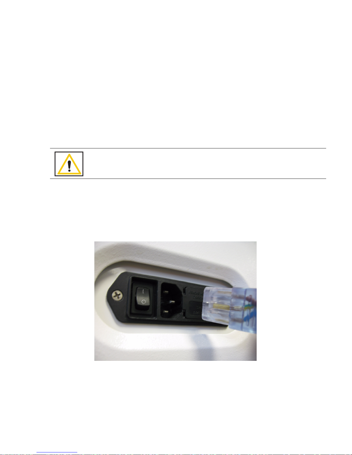
Step 3 Set the power (|/O) switch shown in Figure 2-1 to the | (on) position, and observe that a series
of power-up screens briefly appears on the display.
Figure 2-1 Location of On/Off Switch
Warning!
Inspect the power cord prior to each use, and replace it if damaged. A frayed or worn
cord presents an electrical shock hazard that may result in personal injury or death.
2-3
Chapter 2: Initial Setup and Operation
-
Initial Setup
•
•
•
•
•
•
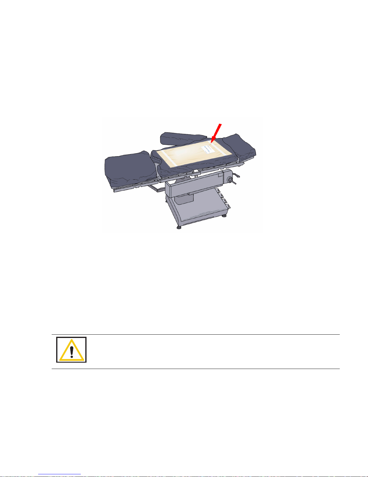
Placing the SmartTag
Before the start of a surgery, a SmartTag must be placed under the patient. Figure 2-2 shows a SmartTag and
its placement. The SmartTag is an adhesive sticker that contains a radio-frequency identification (RFID) tag.
This tag provides feedback to the SmartSponge System that the SmartWand is reading through the depth of the
patient when a scan is performed.
Figure 2-2 SmartTag Placement
During pre-surgery setup, proceed as follows:
Step 1 Peel the backing from the SmartTag.
Step 2 Position the SmartTag below the surgical site and apply between the OR table sheets.
Step 3 Place the tag adhesive-side down.
Warning!
The SmartTag is not approved for application to the patient’s skin.

Chapter 2: Initial Setup and Operation - Initial Setup 2-4
•
•
•
•
•
•
Boot-up Screens
After the on/off switch is set to on (|), the Starting screens shown in Figure 2-3 appear.
Starting Screen
The Starting Screen, shown at the top of Figure 2-3, appears on the display first for 10 seconds after the on/off
switch is set to on.
Boot Screen
The Boot Screen, which follows the Starting Screen appears for 3 seconds. Shown in the center of Figure 2-3,
this screen shows the version of system firmware and the device (SmartSponge System) identification (ID).
Diagnostic Screen
The Diagnostic Screen, shown at the bottom of Figure 2-3, appears for 9 seconds. This screen has a Progress
Bar that fills in from left to right in segments. When the bar completely fills in, the system displays the Standby
(ON) screen. See Figure 2-4. The
Standby
Screen remains on the display until the user presses the
ON
button
to start or continue a surgical case.

2-5
Chapter 2: Initial Setup and Operation
-
Initial Setup
•
•
•
•
•
•
Figure 2-3 Boot-up Screens
Boot Screen
Starting Screen
Diagnostic Screen

Chapter 2: Initial Setup and Operation - Initial Setup 2-6
•
•
•
•
•
•
Standby Mode
Following the startup screens, the
Standby
screen appears, and the system enters Standby Mode. The system
may be left in this state when not in use.
The Standby Mode of operations is the starting point for operating the SmartSponge System. The system can
remain in this mode for as long as necessary while you prepare for surgery. The SmartSponge System enters
the standby mode under the following conditions:
•
When the system powers up, it automatically enters the Standby Mode.
•
When you press the
OFF
button on the
Count Mode
screen during a surgical case. To resume normal
system operation and return to the case, press the
ON
button shown in Figure 2-4.
•
When a power failure occurs; upon restoration of power, the system will returned to the Standby
Screen to allow restoration of the current case.
When you are ready to begin a new surgical case, press the ON button on the
Standby
screen.
Figure 2-4 Standby Screen
Other manuals for SmartSponge
1
Table of contents
Other ClearCount Medical Equipment manuals


