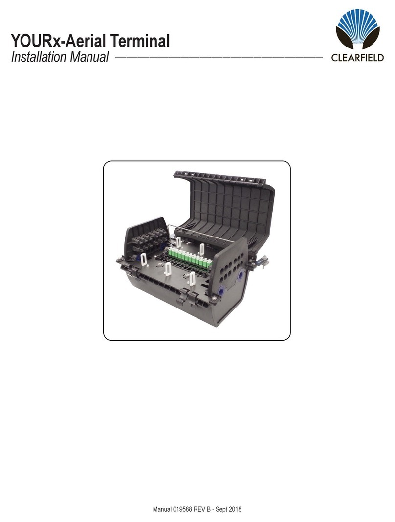
Clearfield YOURx User manual

YOURx Multi-Purpose Terminal
Installation Manual ______________________________________________________
Manual 021023 REV A - Jan 2020

Direct: 763.476.6866 • National: 800.422.2537 • www.SeeCleareld.com • [email protected]
2
YOURx Multi-Purpose Terminal
Installation Manual _________________________________________________________
Manual 021023 REV A - Jan 2020
Table of Contents
Application 3
Description 3
Technical Specications 3
Parts 4
Tools Needed 4
Congurations 6
Deployment/Mounting 7
Accessing the Terminal 9
Capacity 10
Splicing in the Multi-Purpose Terminal 12
Mid-Spanning Buffer Tubes 14
Splicing Pre-Connectorized Fiber Pigtails 16
Splicing Cleareld’s FLATdrop 18
Splicing in MOCs with Drops 20
Grounding 21
Cable Sealing 23
Pre-Connectorized Drop Installation 26
Microduct 27
FLATdrop 28
Installing Duplex LC Pre-Connectorized Drops 30
Connector Cleaning Procedure 31
Standard Warranty 36
Proprietary Notice 37
Technical Support 37

3
YOURx Multi-Purpose Terminal
__________________________________________________________ Installation Manual
Direct: 763.476.6866 • National: 800.422.2537 • www.SeeCleareld.com • [email protected]
Manual 021023 REV A - Jan 2020
Application
Technical Specications
YOURx Multi-Purpose Terminal (MPT)
Dimensions 12.44”L x 6.76”W x 5.49”H (315.97 mm x 171.70 mm x 139.44 mm)
Mounting Options
Below Grade: Vaults - V5A-AZP (17” x 30” x 24”) or V6A-AZP (24” x 36” 24”)
Above Ground: Pedestals - FPP-8820 (8” x 8” with 12” high base), FPP-101020 (10” x 10” with 20”
high base) or FPP-121230 (12” x 12” with 30” high base)
Pole or Aerial/Strand
Internal Slack 8’ of 12 ber buffer tube
Feeder Cable Accepts cable diameter of up to .70” (17.78 mm)
Distribution Ports Eight 14 mm ports; ports are designed to accept FieldShield FlexConnector
Connector Types SC/APC, SC/UPC, LC/APC, LC/UPC and MPO Duplex
Material Black UV Resistant Thermoplastic
Weight 4lbs
Description
The YOURx Multi-Purpose Terminal is a sealed mid-span terminal
that will accept cables with a diameter up to 0.7” (17.78mm). The
terminal includes eight individual sealed distribution drops with remov-
able tabs - all air and water-tight via YOURx FlexPort technology. The
snap-in splice chip will support 12 loose tube splices or 3 mass fusion
(36 bers) splices, with the ability to store up to 8 feet per buffer tube.
The terminal cable entry point uses a split sleeve grommet design for
easy installation. The slide out adapter plate allows installers easy
access for cleaning or testing connectors, if required. The bulkhead
allows for mounting of optical components, splitters, WDMs and
DWDMs. When accessing the terminal, a standard can wrench is the
only tool required. The terminal can be deployed above grade, below
grade, on a pole mount, or in an aerial mount.
Designed for network design exibility, Cleareld’s YOURx Multi-
Purpose Terminal (MPT) is optimized for deployments requiring mid-
span, ber drop, splitter or optical component capabilites

Direct: 763.476.6866 • National: 800.422.2537 • www.SeeCleareld.com • [email protected]
4
YOURx Multi-Purpose Terminal
Installation Manual _________________________________________________________
Manual 021023 REV A - Jan 2020
Parts
15
Front View
12
3
13
5
16
8
7
6
1
14
2
Tools Needed
Pulling tool (For MPO FLATdrop)
De-burring tool
Cigar cutter
Rotary cutter
FlexPort release tool
Can wrench
Flat screwdriver
Tools for cable prep and splicing
1. Terminal Cover
2. Terminal Bulkhead
3. Terminal Faceplate
4. Terminal Collar
5. Terminal Seal
6. Splice Chip
7. Splice Tray Cover
8. Adapter Plate
9. Strength Member Clamp
10. Gasket Plate
11. Gasket
12. Gasket Film Cover
13. FlexPorts
14. Vibration Grommet
15. BOLT,HEX HEAD, 1/4-
20X3/4” 18-8 SST
16. BOLT,HEX HEAD,1/4”-20 x
1.00”
17. NUT, HEX THIN SST 1/4-20
18. WASHER, RETAINING,
.213”ID X .50”OD X .025”
THK, PVC
Additional Hardware

5
YOURx Multi-Purpose Terminal
__________________________________________________________ Installation Manual
Direct: 763.476.6866 • National: 800.422.2537 • www.SeeCleareld.com • [email protected]
Manual 021023 REV A - Jan 2020
Back View
9
16
4
4
15
18
11
10

Direct: 763.476.6866 • National: 800.422.2537 • www.SeeCleareld.com • [email protected]
6
YOURx Multi-Purpose Terminal
Installation Manual _________________________________________________________
Manual 021023 REV A - Jan 2020
Congurations
Option 1: Patch
Only Stubbed
Version
Option 2: Dead
End Splice (In
Terminal Splicing)
Option 3: Mid Span
(In Terminal
Splicing)
Option 4: Plug and
Play (MPO Feed)
Option 5: Plug
and Play (Optical
Component)

7
YOURx Multi-Purpose Terminal
__________________________________________________________ Installation Manual
Direct: 763.476.6866 • National: 800.422.2537 • www.SeeCleareld.com • [email protected]
Manual 021023 REV A - Jan 2020
Deployment/Mounting
Below Grade Deployment
Much like a typical splice case, the MPT can be coiled into the base of a vault/below grade enclosure.
Wall & Pole (Wood) Mounting
The mounting bracket for the MPT
can be secured to the wall or pole via
preferred hardware. Then attach the
MPT to the mounting bracket with the
4 provided screws in the holes at the
base of the terminal.
Note: Cleareld recommends to orient
the MPT mounting bracket with the 4
MPT mounting holes on the bottom of
the bracket.
Pole (Metal) Mounting
In order to secure the MPT mounting bracket to the metal pole, the customer
will need to supply band clamps. Place the band clamps through the two sets of
bridge lances as shown, and tight them around the pole. Proceed to mounting the
MPT to the MPT mounting bracket with the 4 screws provided.
Pedestal Mounting
Mount the pedestal mounting
bracket into the pedestal.
Secure the MPT to the pedestal
mounting bracket by the holes in
the tabs on the MPT lid, using the
bolts and wing nuts supplied with
the bracket
1.
2.

Direct: 763.476.6866 • National: 800.422.2537 • www.SeeCleareld.com • [email protected]
8
YOURx Multi-Purpose Terminal
Installation Manual _________________________________________________________
Manual 021023 REV A - Jan 2020
Aerial Mounting
1. Using the hardware provided, secure the adjustable aerial mounting brackets to the base MPT mounting bracket. The 3
slotted holes on each aerial mounting bracket will allow for a wide range of heights.
2.
3.
Install the MPT onto the base MPT mounting bracket. This will attach via four screws into holes on the base of the
MPT.
Using a can wrench, loosen the bug nuts on the aerial mounting brackets. Place the bug nuts around the strand in the
desired location and tighten the bug nuts.

9
YOURx Multi-Purpose Terminal
__________________________________________________________ Installation Manual
Direct: 763.476.6866 • National: 800.422.2537 • www.SeeCleareld.com • [email protected]
Manual 021023 REV A - Jan 2020
Accessing the Terminal
In order to access the internals of the MPT, you must remove the
collar and pull off the lid.
Loosen the bolt holding the collar closed with a can wrench.
Remove the collar and pull off the lid.
To re-install the lid, follow these steps in reverse, making
sure you match the sides of the lid and MPT body with white
marks on them so the internals will align.
1.
3.
2.

Direct: 763.476.6866 • National: 800.422.2537 • www.SeeCleareld.com • [email protected]
10
YOURx Multi-Purpose Terminal
Installation Manual _________________________________________________________
Manual 021023 REV A - Jan 2020
Capacity
The YOURx Multi-Purpose Terminal is recommended for use with a max
cable OD of 0.7 inches, with a possibility to midspan.
The terminal is capable of storing up to 8 feet of buffer tuber depending on
cable size.
The terminal will accept up to 8 ber drops connected through the 14mm
ports.
The terminal will support up to 12 loose tube splices or
three ribbon ber mass fusion splices.
Slack Storage
Splice Tray

11
YOURx Multi-Purpose Terminal
__________________________________________________________ Installation Manual
Direct: 763.476.6866 • National: 800.422.2537 • www.SeeCleareld.com • [email protected]
Manual 021023 REV A - Jan 2020
Adapter Plate Capacity and Conguration
8 SC Adapters 12 LC Adapters
Adapter Plate Port Assignment
5678
1234
9 10 11 12 13 14 15 16
12345678
SC Duplex Adapters LC Quadplex Adapters*
*Up to 16
ports in certain
congurations
if dual LC ber
drops
3456
IN OUT 1 2
Top Row
Bottom Row
123456
IN OUT
Note: MPO Duplex Adapter will populate one section. The OUT MPO is for expressing bers, and will be blank if not
congured to do so.
SC Duplex Adapters with MPO LC Quadplex Adapters with MPO

Direct: 763.476.6866 • National: 800.422.2537 • www.SeeCleareld.com • [email protected]
12
YOURx Multi-Purpose Terminal
Installation Manual _________________________________________________________
Manual 021023 REV A - Jan 2020
Splicing in the Multi-Purpose Terminal
1.
2.
3.
Prep your cable. Cleareld recommends opening no more than 8 ft (96”) of
cable.
Cut the strength members to roughly 5 inches in length.
Place the hose clamps through the clamp locations on the terminal bulkhead.
4.
5.
Insert the buffer tubes (mid-span or dead end) through the cable entrance on
the base of the terminal.
Place the cables into the hose clamps and tighten.
6.
7.
Attach the strength member clamp
bracket with the nut and bold provid-
ed, ensure the strength members are
in place below the strength member
clamp and tighten.
Once strength members are secured
into place, trim them to length just
behind the strength member clamp.

13
YOURx Multi-Purpose Terminal
__________________________________________________________ Installation Manual
Direct: 763.476.6866 • National: 800.422.2537 • www.SeeCleareld.com • [email protected]
Manual 021023 REV A - Jan 2020
Pass the buffer tubes/ribbons to be splice through the slot on the chosen side of the bulkhead, transitioning the ber
from the back of the terminal to the front. It is recommended to place zip ties/wax string before storing buffer tubes.
Store the remaining buffer tubes in the slack storage area, coiling it neatly into place and securing with a velcro strap
across the top.
8.
9.
Place a zip tie or piece of wax string into the tie-down location in the terminal.
Note that buffer tubes/ribbons can be secured to either side of the splicing area.
From the tie-down location, measure 30 inches and trim your ber. Open up the
buffer tube from after the tie-down location, exposing the 250 micron bers.
Wrap one lap of grommet tape around the buffer tube approximately 1/4 inch
behind the opening, and secure it into place at the tie-down location using the zip
tie or piece of wax string.
10.
11.
12.
Route the bers into the splice tray.
Install the splice chip into the slot at the center of the splice tray.
Route the bers to be spliced (keeping others stored) and bring them into the
splice chip. Trim bers to length at the center of the splice chip.
Note: Cleareld recommends at least 1.5 laps of slack stored in the splice tray.
13.
14.
15.

Direct: 763.476.6866 • National: 800.422.2537 • www.SeeCleareld.com • [email protected]
14
YOURx Multi-Purpose Terminal
Installation Manual _________________________________________________________
Manual 021023 REV A - Jan 2020
Mid-Spanning Buffer Tubes
The following are instructions for mid-
spanning a single buffer tube inside the MPT,
and expressing the remaining bers that aren’t
spliced.
1.
2.
Prior to storing the remaining buffer tubes
in the back of the MPT, bring one side of
the buffer tube to be mid-spanned through
the opening on the side of the bulkhead.
Repeat for the other side so that all the
slack in the buffer tube is located in front
of the terminal.
3. Utilize the tie down areas within the bulk-
head, mark the buffer tube on each side
approximately 1/2” above this tie down
point.
Using the appropriate tool, mid-span the buffer tube to expose the bers be-
tween the marks you made on the buffer tube.
4.

15
YOURx Multi-Purpose Terminal
__________________________________________________________ Installation Manual
Direct: 763.476.6866 • National: 800.422.2537 • www.SeeCleareld.com • [email protected]
Manual 021023 REV A - Jan 2020
Follow instructions for splicing in the terminal, i.e. FLATdrop, pre-connectorized
pigtails, or MOCs.
Store the slack from the splices as well as the remaining bers that are being
expressed.
With grommet tape, felt tape, or your local
practice, protect the buffer tube by wrap-
ping the material around the buffer tubes
approximately 1/8” before the openings.
Note: If using grommet tape, it is recom-
mended to wrap buffer tube by folding
tape over and then trimming.
5.
Tie down the buffer tubes on both side of the bulkhead as shown with zip ties or wax string. If using zip ties, be sure to
only tighten until it is “snug” and not damage the buffer tube.
6.
7.

Direct: 763.476.6866 • National: 800.422.2537 • www.SeeCleareld.com • [email protected]
16
YOURx Multi-Purpose Terminal
Installation Manual _________________________________________________________
Manual 021023 REV A - Jan 2020
Locate the ber assembly that was ordered for the terminal. Remove
the twist ties from the bers, and save both halves for later.
Note: Fiber test record will be included. Place onto splice tray cover
for future use.
Splicing Pre-Connectorized Fiber Pigtails
1.
Splice each of these bers to the assigned incoming ber. Place the
splice sleeves into the splice chip.
Note: Slice chip carries a maximum of 12 sleeves (6 slots, 2 sleeves
per slot).
Store the 250 micron ber back into the tray.
2.
3.
Route the 900 micron ber down and around the bottom of the tray,
and out of the top of the terminal. Install the splice tray cover, allowing
the 900 micron ber to exit the gap in the splice tray cover.
4.

17
YOURx Multi-Purpose Terminal
__________________________________________________________ Installation Manual
Direct: 763.476.6866 • National: 800.422.2537 • www.SeeCleareld.com • [email protected]
Manual 021023 REV A - Jan 2020
5.
6.
Install the adapters into the adapter plate.
Inspect and clean the ber endfaces and connect
them into the back side of the adapters.
Note: The underside of the back half of the adapter
plate will have a metal clip.
7.
8.
Gently coil the 900 micron bers and place the two
white twist ties around the bers to keep them in a
neat loop and lay them on top of the splice tray cover.
Insert the adapter plate into its location just below the
splice tray.

Direct: 763.476.6866 • National: 800.422.2537 • www.SeeCleareld.com • [email protected]
18
YOURx Multi-Purpose Terminal
Installation Manual _________________________________________________________
Manual 021023 REV A - Jan 2020
Splicing Cleareld’s FLATdrop
After opening and tying the buffer tube into the splice tray on
the desired side (Cleareld recommends opening a minimum of
30 inches of buffer tube) store the bare 250 micron ber in the
entire splice tray. This will allow for subsequent users to have
easier access to the bers when splicing additional drops at a
later time.
1.
Prepare the at drop, opening at least 30 inches of the cable to
expose the inner buffer tube.
If using a Field Installable FlexConnector, reference the sec-
tion for FLATdrop drops in this manual and follow the provided
instructions for installing the FlexConnector. If using a factory
installed FlexConnector, skip to the next step.
Insert the ber through the FlexPort and into the terminal bulk-
head. Fully seat the FlexConnector into the FlexPort.
2.
3.
4.

19
YOURx Multi-Purpose Terminal
__________________________________________________________ Installation Manual
Direct: 763.476.6866 • National: 800.422.2537 • www.SeeCleareld.com • [email protected]
Manual 021023 REV A - Jan 2020
Bring the buffer tubes to the opposite side of the MPT bulkhead that the
original buffer tube is secured to. You will secure the buffer tubes down
at this location. Mark the length to reach the tie-down location on each
buffer tube, and open the tubes 1/2 inch after that to expose the 900
micron bers.
Secure all buffer tubes in place with velcro, or grommet tape and zip
ties.
5.
6.
Store the 900 micron bers to be spliced in the upper splice tray. Wrap 1
1/2 laps of ber and bring them to the center of the splice chip, then trim
them to length. Do the same with the 250 micron bers to be spliced.
Perform your splices and place the splice sleeves in the splice chip in
the center of the splice tray. Store the slack inside the upper portion of
the splice tray and reinstall the splice tray cover.
7.
8.

Direct: 763.476.6866 • National: 800.422.2537 • www.SeeCleareld.com • [email protected]
20
YOURx Multi-Purpose Terminal
Installation Manual _________________________________________________________
Manual 021023 REV A - Jan 2020
Splicing in MOCs with Drops
MOC congurations of the Multi-Purpose Terminal will come with the MOC pre-installed and the distribution leg connectors
loaded into the adapter plate. Simply splice in the feeder tail or connect the feed drop as shown in the splicing and drop
sections of this manual.
This manual suits for next models
1
Table of contents
Other Clearfield Touch Terminal manuals
Popular Touch Terminal manuals by other brands
Uni-Ubi
Uni-Ubi Uface 7 Pro Product Booklet
Siemens
Siemens Climatix HMI-DM Basic documentation

Firich Enterprise
Firich Enterprise Gladius Smart user manual

gefran
gefran Vedo EL35CT Installation and operation manual
Emerson
Emerson FB3000 Field installation guide
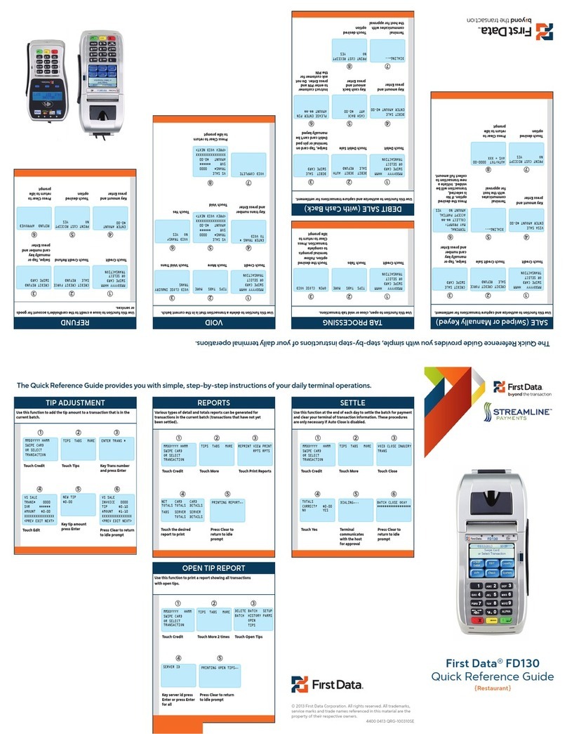
First Data
First Data FD130 Quick reference guide

Titus
Titus DLSC Installation, operation and maintenance
Tunstall
Tunstall ComTerminal Flamenco installation instructions

Symbol
Symbol MC9190 manual
Elo TouchSystems
Elo TouchSystems 15A2 for wireless card user guide

Thrane&Thrane
Thrane&Thrane TT-3710A EXPLORER 500 user manual
VISUAL
VISUAL 200 Reference manual
