Clement Clarke 2001 User manual

Haag-Streit UK Ltd.,
Edinburgh Way,
Harlow,
Essex CM20 2TT UK
Tele: 01279 414969 International: +44 1279 414969
Fax: 01279 635232 International: +44 1279 635232
Catalogue number: 1902499
Issue number: 4 03/15
0120
CLEMENT CLARKE
OPHTHALMIC
For the full IFU (I structio s for use) see Haag-Streit UK website
www.haagstreituk.com/ifu

Synoptophore
Instruction Manual
Models 2001, 2002, 2003


Synoptophore
Contents
Page 2
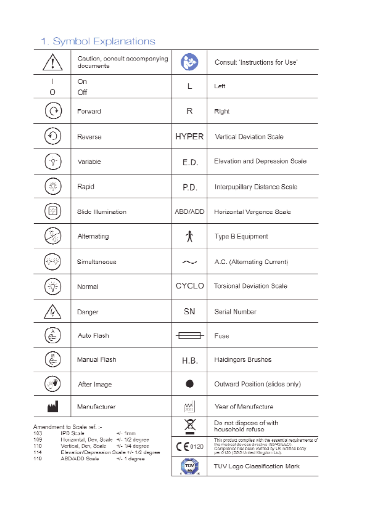
1.
Symbol Explanations
Page 3
2.
Intended Use
Page 3
3. Safety and Regulatory Information
Page 4
Synoptophore Panels - General Layout
Page 5
4. Unpacking the Instrument
5. Electical Connection
6. Adjusting Instrument to Patient
7. Measuring the Angle Alpha
8. Measuring the Objective Angle
Page 6
9. Subjective Angle and A.R.C.
10. Side Movements
11. Vergences
12. Heterophoria
13. Dimming Rheostats
14. Hand Flashing Switches
15. Auxiliary Lens Holders
16. Slide Ejectors
17. Promoting an After-Image (2001 and 2002 models only)
Page 7
18. Automatic flashing
19. Haidinger’s brushes (2001 model only)
Page 8
20. Changing Lamps and Fuses
Page 9
21. Cleaning
Page 10
22. Correct Disposal of this Product
Page 11
23. Device Ranges and Tolerances
Page 12/13
Illustrated diagram model 2001
Page 14/15
Illustrated diagram model 2002
Page 16/17
Illustrated diagram model 2003
Page 18
List of Synoptophore Slides
1
The suppliers cannot accept responsibility for the
performance, reliability or safety of this equipment if it
has been installed, serviced or modified by unauthorised
persons. The equipment must be connected only to an
approved electrical supply and used in accordance with
this instruction booklet.
Users may obtain, on request, information sufficient to
allow repairs to those parts classified by the suppliers
as repairable.
Whilst this information is provided in good faith and is
based on the latest information available at the time of
issue, this manual gives only a general indication of
product capacity, performance and suitability. Such
information must not be taken as establishing any
contractural or other commitment on the part of the
manufacturer and in no way should be constructed as a
warranty or representation concerning the product.
2
This manual suits for next models
2
Table of contents
Other Clement Clarke Medical Equipment manuals

Clement Clarke
Clement Clarke Perkins Mk2 User manual

Clement Clarke
Clement Clarke In-Check M User manual

Clement Clarke
Clement Clarke AirMed Travel-Air CN03A User manual

Clement Clarke
Clement Clarke In-Check DIAL G16 User manual

Clement Clarke
Clement Clarke A2A Spacer User manual

Clement Clarke
Clement Clarke AirMed 1000 User manual
Popular Medical Equipment manuals by other brands


Getinge
Getinge Arjohuntleigh Nimbus 3 Professional Instructions for use

Mettler Electronics
Mettler Electronics Sonicator 730 Maintenance manual

Pressalit Care
Pressalit Care R1100 Mounting instruction

Denas MS
Denas MS DENAS-T operating manual

bort medical
bort medical ActiveColor quick guide

AccuVein
AccuVein AV400 user manual


